About VXLAN Interfaces
VXLAN provides the same Ethernet Layer 2 network services as VLAN does, but with greater extensibility and flexibility. Compared to VLAN, VXLAN offers the following benefits:
-
Flexible placement of multitenant segments throughout the data center.
-
Higher scalability to address more Layer 2 segments: up to 16 million VXLAN segments.
This section describes how VXLAN works. For detailed information about VXLAN, see RFC 7348. For detailed information about Geneve, see RFC 8926.
Encapsulation
The ASA supports two types of VXLAN encapsulation:
-
VXLAN (all models)—VXLAN uses MAC Address-in-User Datagram Protocol (MAC-in-UDP) encapsulation. The original Layer 2 frame has a VXLAN header added and is then placed in a UDP-IP packet.
-
Geneve (ASA virtual only)—Geneve has a flexible inner header that is not limited to the MAC address. Geneve encapsulation is required for transparent routing of packets between an Amazon Web Services (AWS) Gateway Load Balancer and appliances, and for sending extra information.
VXLAN Tunnel Endpoint
VXLAN tunnel endpoint (VTEP) devices perform VXLAN encapsulation and decapsulation. Each VTEP has two interface types: one or more virtual interfaces called VXLAN Network Identifier (VNI) interfaces to which you apply your security policy, and a regular interface called the VTEP source interface that tunnels the VNI interfaces between VTEPs. The VTEP source interface is attached to the transport IP network for VTEP-to-VTEP communication.
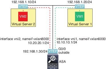
The following figure shows two ASAs and Virtual Server 2 acting as VTEPs across a Layer 3 network, extending the VNI 1, 2, and 3 networks between sites. The ASAs act as bridges or gateways between VXLAN and non-VXLAN networks.
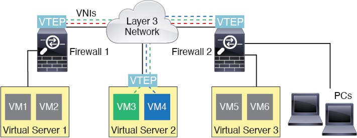
The underlying IP network between VTEPs is independent of the VXLAN overlay. Encapsulated packets are routed based on the outer IP address header, which has the initiating VTEP as the source IP address and the terminating VTEP as the destination IP address. For VXLAN encapsulation: The destination IP address can be a multicast group when the remote VTEP is not known. With Geneve, the ASA only supports static peers. The destination port for VXLAN is UDP port 4789 by default (user configurable). The destination port for Geneve is 6081.
VTEP Source Interface
The VTEP source interface is a regular ASA interface (physical, EtherChannel, or even VLAN) with which you plan to associate all VNI interfaces. You can configure one VTEP source interface per ASA/security context. Because you can only configure one VTEP source interface, you cannot configure both VXLAN and Geneve interfaces on the same device.There is an exception for ASA virtual clustering on AWS or Azure, where you can have two VTEP source interfaces: a VXLAN interface is used for the cluster control link, and a Geneve (AWS) or VXLAN (Azure) interface can be used for the Gateway Load Balancer.
The VTEP source interface can be devoted wholly to VXLAN traffic, although it is not restricted to that use. If desired, you can use the interface for regular traffic and apply a security policy to the interface for that traffic. For VXLAN traffic, however, all security policy must be applied to the VNI interfaces. The VTEP interface serves as a physical port only.
In transparent firewall mode, the VTEP source interface is not part of a BVI, and you do configure an IP address for it, similar to the way the management interface is treated.
VNI Interfaces
VNI interfaces are similar to VLAN interfaces: they are virtual interfaces that keep network traffic separated on a given physical interface by using tagging. You apply your security policy directly to each VNI interface.
You can only add one VTEP interface, and all VNI interfaces are associated with the same VTEP interface. There is an exception for ASA virtual clustering on AWS or Azure. For AWS clustering, you can have two VTEP source interfaces: a VXLAN interface is used for the cluster control link, and a Geneve interface can be used for the AWS Gateway Load Balancer.For Azure clustering, you can have two VTEP source interfaces: a VXLAN interface is used for the cluster control link, and a second VXLAN interface can be used for the Azure Gateway Load Balancer.
VXLAN Packet Processing
VXLAN
Traffic entering and exiting the VTEP source interface is subject to VXLAN processing, specifically encapsulation or decapsulation.
Encapsulation processing includes the following tasks:
-
The VTEP source interface encapsulates the inner MAC frame with the VXLAN header.
-
The UDP checksum field is set to zero.
-
The Outer frame source IP is set to the VTEP interface IP.
-
The Outer frame destination IP is decided by a remote VTEP IP lookup.
Decapsulation; the ASA only decapsulates a VXLAN packet if:
-
It is a UDP packet with the destination port set to 4789 (this value is user configurable).
-
The ingress interface is the VTEP source interface.
-
The ingress interface IP address is the same as the destination IP address.
-
The VXLAN packet format is compliant with the standard.
Geneve
Traffic entering and exiting the VTEP source interface is subject to Geneve processing, specifically encapsulation or decapsulation.
Encapsulation processing includes the following tasks:
-
The VTEP source interface encapsulates the inner MAC frame with the Geneve header.
-
The UDP checksum field is set to zero.
-
The Outer frame source IP is set to the VTEP interface IP.
-
The Outer frame destination IP is set the peer IP address that you configured.
Decapsulation; the ASA only decapsulates a Geneve packet if:
-
It is a UDP packet with the destination port set to 6081 (this value is user configurable).
-
The ingress interface is the VTEP source interface.
-
The ingress interface IP address is the same as the destination IP address.
-
The Geneve packet format is compliant with the standard.
Peer VTEP
When the ASA sends a packet to a device behind a peer VTEP, the ASA needs two important pieces of information:
-
The destination MAC address of the remote device
-
The destination IP address of the peer VTEP
The ASA maintains a mapping of destination MAC addresses to remote VTEP IP addresses for the VNI interfaces.
VXLAN Peer
There are two ways in which the ASA can find this information:
-
A single peer VTEP IP address can be statically configured on the ASA.
You cannot manually define multiple peers.
For IPv4: The ASA then sends a VXLAN-encapsulated ARP broadcast to the VTEP to learn the end node MAC address.
For IPv6: The ASA then sends an IPv6 Neighbor Solicitation message to the IPv6 solicited-node multicast address. The peer VTEP responds with an IPv6 Neighbor Advertisement message with its link-local address.
-
A multicast group can be configured on each VNI interface (or on the VTEP as a whole).

Note
This option is not supported with Geneve.
For IPv4: The ASA sends a VXLAN-encapsulated ARP broadcast packet within an IP multicast packet through the VTEP source interface. The response to this ARP request enables the ASA to learn both the remote VTEP IP address along with the destination MAC address of the remote end node.
For IPv6: The ASA sends a Multicast Listener Discovery (MLD) Report message through the VTEP source interface to indicate that the ASA is listening on the VTEP interface for the multicast address traffic.
Geneve Peer
The ASA virtual only supports statically defined peers. You can define the ASA virtual peer IP address on the AWS Gateway Load Balancer. Because the ASA virtual never initiates traffic to the Gateway Load Balancer, you do not also have to specify the Gateway Load Balancer IP address on the ASA virtual; it learns the peer IP address when it receives Geneve traffic. Multicast groups are not supported with Geneve.
VXLAN Use Cases
This section describes the use cases for implementing VXLAN on the ASA.
VXLAN Bridge or Gateway Overview
Each ASA VTEP acts as a bridge or gateway between end nodes such as VMs, servers, and PCs and the VXLAN overlay network. For incoming frames received with VXLAN encapsulation over the VTEP source interface, the ASA strips out the VXLAN header and forwards it to a physical interface connected to a non-VXLAN network based on the destination MAC address of the inner Ethernet frame.
The ASA always processes VXLAN packets; it does not just forward VXLAN packets untouched between two other VTEPs.

VXLAN Bridge
When you use a bridge group (transparent firewall mode, or optionally routed mode), the ASA can serve as a VXLAN bridge between a (remote) VXLAN segment and a local segment where both are in the same network. In this case, one member of the bridge group is a regular interface while the other member is a VNI interface.

VXLAN Gateway (Routed Mode)
The ASA can serve as a router between VXLAN and non-VXLAN domains, connecting devices on different networks.
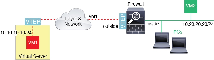
Router Between VXLAN Domains
With a VXLAN-stretched Layer 2 domain, a VM can point to an ASA as its gateway while the ASA is not on the same rack, or even when the ASA is far away over the Layer 3 network.


See the following notes about this scenario:
-
For packets from VM3 to VM1, the destination MAC address is the ASA MAC address, because the ASA is the default gateway.
-
The VTEP source interface on Virtual Server 2 receives packets from VM3, then encapsulates the packets with VNI 3’s VXLAN tag and sends them to the ASA.
-
When the ASA receives the packets, it decapsulates the packets to get the inner frames.
-
The ASA uses the inner frames for route lookup, then finds that the destination is on VNI 2. If it does not already have a mapping for VM1, the ASA sends an encapsulated ARP broadcast on the multicast group IP on VNI 2.
Note
The ASA must use dynamic VTEP peer discovery because it has multiple VTEP peers in this scenario.
-
The ASA encapsulates the packets again with the VXLAN tag for VNI 2 and sends the packets to Virtual Server 1. Before encapsulation, the ASA changes the inner frame destination MAC address to be the MAC of VM1 (multicast-encapsulated ARP might be needed for the ASA to learn the VM1 MAC address).
-
When Virtual Server 1 receives the VXLAN packets, it decapsulates the packets and delivers the inner frames to VM1.
AWS Gateway Load Balancer and Geneve Single-Arm Proxy
Note |
This use case is the only currently supported use case for Geneve interfaces. |
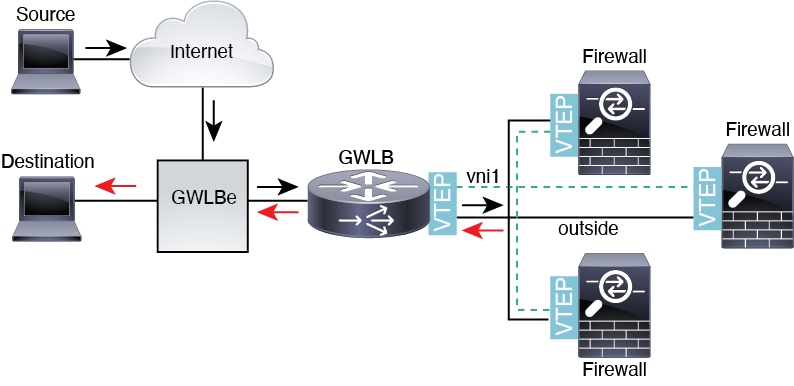
The AWS Gateway Load Balancer combines a transparent network gateway and a load balancer that distributes traffic and scales virtual appliances on demand. The ASA virtual supports the Gateway Load Balancer centralized control plane with a distributed data plane (Gateway Load Balancer endpoint). The following figure shows traffic forwarded to the Gateway Load Balancer from the Gateway Load Balancer endpoint. The Gateway Load Balancer balances traffic among multiple ASA virtuals, which inspect the traffic before either dropping it or sending it back to the Gateway Load Balancer (U-turn traffic). The Gateway Load Balancer then sends the traffic back to the Gateway Load Balancer endpoint and to the destination.
AWS Gateway Load Balancer and Geneve Dual-Arm Proxy
Note |
This use case is the only currently supported use case for Geneve interfaces. |
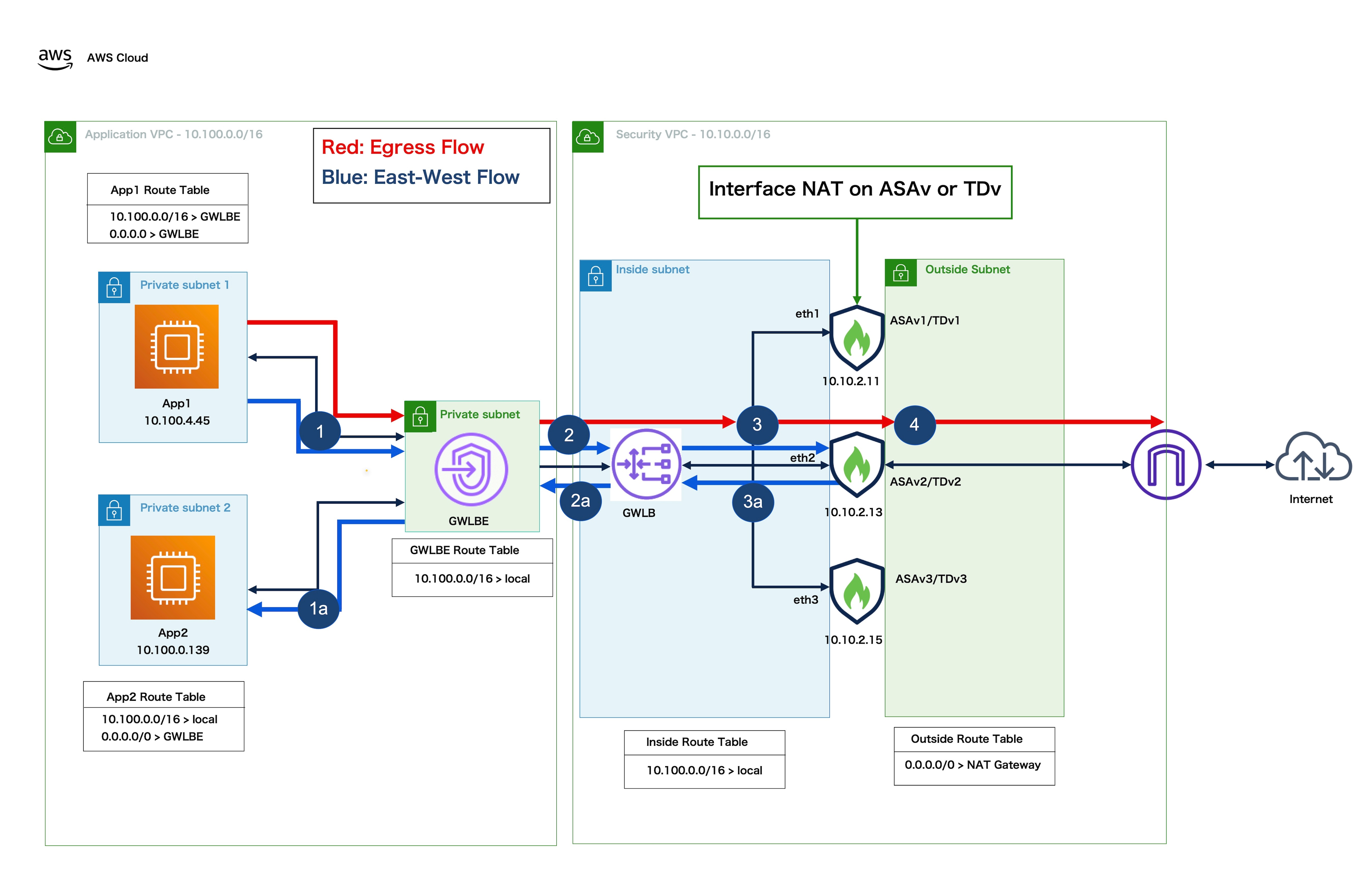
The ASA virtual supports the Gateway Load Balancer centralized control plane with a distributed data plane (Gateway Load Balancer endpoint) with single-arm and dual-arm mode. The following figure shows outbound traffic (traffic inspected by ASA virtual) directly forwarded to the destination (Internet) without the need for traffic hop to the GWLB and GWLB endpoint. The ASA virtual inspect the outbound and perform NAT of the traffic before either dropping it or sending it back to the internet via NAT gateway. Dual-arm proxy provides a common egress path for multi-VPC deployment. The firewall inspects the outbound traffic from multiple VPCs, and it exits from a single point to the Internet, making it a cost-effective infrastructure solution.

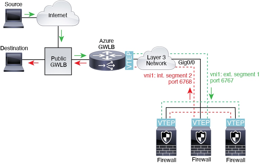
Azure Gateway Load Balancer and Paired Proxy
In an Azure service chain, ASA virtuals act as a transparent gateway that can intercept packets between the internet and the customer service. The ASA virtual defines an external interface and an internal interface on a single NIC by utilizing VXLAN segments in a paired proxy.
The following figure shows traffic forwarded to the Azure Gateway Load Balancer from the Public Gateway Load Balancer on the external VXLAN segment. The Gateway Load Balancer balances traffic among multiple ASA virtuals, which inspect the traffic before either dropping it or sending it back to the Gateway Load Balancer on the internal VXLAN segment. The Azure Gateway Load Balancer then sends the traffic back to the Public Gateway Load Balancer and to the destination.

 Feedback