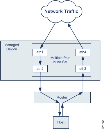
Inline Sets and Passive Interfaces

You can configure IPS-only passive interfaces, passive ERSPAN interfaces, and inline sets. IPS-only mode interfaces bypass many firewall checks and only support IPS security policy. You might want to implement IPS-only interfaces if you have a separate firewall protecting these interfaces and do not want the overhead of firewall functions.

About IPS Interfaces

This section describes IPS interfaces.

IPS Interface Types

IPS-only mode interfaces bypass many firewall checks and only support IPS security policy. You might want to implement IPS-only interfaces if you have a separate firewall protecting these interfaces and do not want the overhead of firewall functions.


Note


The firewall mode only affects regular firewall interfaces, and not IPS-only interfaces such as inline sets or passive interfaces. IPS-only interfaces can be used in both firewall modes.


IPS-only interfaces can be deployed as the following types:

  • Inline Set, with optional Tap mode—An inline set acts like a bump on the wire, and binds two interfaces together to slot into an existing network. This function allows the FTD to be installed in any network environment without the configuration of adjacent network devices. Inline interfaces receive all traffic unconditionally, but all traffic received on these interfaces is retransmitted out of an inline set unless explicitly dropped.

    With tap mode, the FTD is deployed inline, but the network traffic flow is undisturbed. Instead, the FTD makes a copy of each packet so that it can analyze the packets. Note that rules of these types do generate intrusion events when they are triggered, and the table view of intrusion events indicates that the triggering packets would have dropped in an inline deployment. There are benefits to using tap mode with FTDs that are deployed inline. For example, you can set up the cabling between the FTD and the network as if the FTD were inline and analyze the kinds of intrusion events the FTD generates. Based on the results, you can modify your intrusion policy and add the drop rules that best protect your network without impacting its efficiency. When you are ready to deploy the FTD inline, you can disable tap mode and begin dropping suspicious traffic without having to reconfigure the cabling between the FTD and the network.


    Note


    Tap mode significantly impacts FTD performance, depending on the traffic.


    Note


    Inline sets might be familiar to you as "transparent inline sets," but the inline interface type is unrelated to the transparent firewall mode or the firewall-type interfaces.


  • Passive or ERSPAN Passive—Passive interfaces monitor traffic flowing across a network using a switch SPAN or mirror port. The SPAN or mirror port allows for traffic to be copied from other ports on the switch. This function provides the system visibility within the network without being in the flow of network traffic. When you configure the FTD in a passive deployment, the FTD cannot take certain actions such as blocking or shaping traffic. Passive interfaces receive all traffic unconditionally. and no traffic received on these interfaces is retransmitted. Encapsulated remote switched port analyzer (ERSPAN) interfaces allow you to monitor traffic from source ports distributed over multiple switches, and uses GRE to encapsulate the traffic. ERSPAN interfaces are only allowed when the FTD is in routed firewall mode.


    Note


    Using SR-IOV interfaces as passive interfaces on NGFWv is not supported on some Intel network adapters (such as Intel X710 or 82599) using SR-IOV drivers due to a promiscuous mode restriction. In such cases, use a network adapter that supports this functionality. See Intel Ethernet Products for more information on Intel network adapters.


About Hardware Bypass for Inline Sets

For certain interface modules on the supported models (see Requirements and Prerequisites for Inline Sets), you can enable the Hardware Bypass feature. Hardware Bypass ensures that traffic continues to flow between an inline interface pair during a power outage. This feature can be used to maintain network connectivity in the case of software or hardware failures.

Hardware Bypass Triggers

Hardware Bypass can be triggered in the following scenarios:

  • FTD crash

  • FTD reboot

  • Security Module reboot

  • Chassis crash

  • Chassis reboot

  • Manual trigger

  • Chassis power loss

  • Security Module power loss


Note


Hardware bypass is intended for unplanned/unexpected failure scenarios, and is not automatically triggered during planned software upgrades. Hardware bypass only engages at the end of a planned upgrade process, when the FTD application reboots.


Hardware Bypass Switchover

When switching from normal operation to hardware bypass or from hardware bypass back to normal operation, traffic may be interrupted for several seconds. A number of factors can affect the length of the interruption; for example, copper port auto-negotiation; behavior of the optical link partner such as how it handles link faults and de-bounce timing; spanning tree protocol convergence; dynamic routing protocol convergence; and so on. During this time, you may experience dropped connections.

You may also experience dropped connections due to application identification errors when analyzing connections midstream after the return to normal operations.

Snort Fail Open vs. Hardware Bypass

For inline sets other than those in tap mode, you can use the Snort Fail Open option to either drop traffic or allow traffic to pass without inspection when the Snort process is busy or down. Snort Fail Open is supported on all inline sets except those in tap mode, not just on interfaces that support Hardware Bypass.

The Hardware Bypass functionality allows traffic to flow during a hardware failure, including a complete power outage, and certain limited software failures. A software failure that triggers Snort Fail Open does not trigger a Hardware Bypass.

Hardware Bypass Status

If the system has power, then the Bypass LED indicates the Hardware Bypass status. See the Firepower chassis hardware installation guide for LED descriptions.

Requirements and Prerequisites for Inline Sets

User Roles

  • Admin

  • Access Admin

  • Network Admin

Hardware Bypass Support

The FTD supports Hardware Bypass for interface pairs on specific network modules on the following models:

  • Firepower 2130 and 2140

  • Firepower 4100

  • Firepower 9300


Note


The ISA 3000 has a separate implementation for Hardware Bypass, which you can enable using FlexConfig only (see FlexConfig Policies). Do not use this chapter to configure ISA 3000 Hardware Bypass.


Note


You can use Hardware Bypass interfaces as regular interfaces without the Hardware Bypass feature enabled.


The supported Hardware Bypass network modules for these models include:

  • Firepower 2130 and 2140:

    • Firepower 6-port 1G SX FTW Network Module single-wide (FPR2K-NM-6X1SX-F)

    • Firepower 6-port 10G SR FTW Network Module single-wide (FPR2K-NM-6X10SR-F)

    • Firepower 6-port 10G LR FTW Network Module single-wide (FPR2K-NM-6X10LR-F)

  • Firepower 4100:

    • Firepower 6-port 1G SX FTW Network Module single-wide (FPR4K-NM-6X1SX-F)

    • Firepower 6-port 10G SR FTW Network Module single-wide (FPR4K-NM-6X10SR-F)

    • Firepower 6-port 10G LR FTW Network Module single-wide (FPR4K-NM-6X10LR-F)

    • Firepower 2-port 40G SR FTW Network Module single-wide (FPR4K-NM-2X40G-F)

    • Firepower 8-port 1G Copper FTW Network Module single-wide (FPR-NM-8X1G-F)

  • Firepower 9300:

    • Firepower 6-port 10G SR FTW Network Module single-wide (FPR9K-NM-6X10SR-F)

    • Firepower 6-port 10G LR FTW Network Module single-wide (FPR9K-NM-6X10LR-F)

    • Firepower 2-port 40G SR FTW Network Module single-wide (FPR9K-NM-2X40G-F)

Hardware Bypass can only use the following port pairs:

  • 1 & 2

  • 3 & 4

  • 5 & 6

  • 7 & 8

Guidelines for Inline Sets and Passive Interfaces

Firewall Mode

  • ERSPAN interfaces are only allowed when the device is in routed firewall mode.

Clustering

  • Link State Propagation for an inline set is not supported with clustering.

Multi-Instance Mode

  • Multi-instance shared interfaces are not supported. You must use an unshared interface.

  • Multi-instance chassis-defined subinterfaces are not supported. You must use a physical interface or EtherChannel.

General Guidelines

  • Inline sets and passive interfaces support physical interfaces and EtherChannels only, and cannot use VLANs or other virtual interfaces, including multi-instance chassis-defined subinterfaces.

  • Bidirectional Forwarding Detection (BFD) echo packets are not allowed through the FTD when using inline sets. If there are two neighbors on either side of the FTD running BFD, then the FTD will drop BFD echo packets because they have the same source and destination IP address and appear to be part of a LAND attack.

  • For inline sets and passive interfaces, the FTD supports up to two 802.1Q headers in a packet (also known as Q-in-Q support), with the exception of the Firepower 4100/9300, which only supports one 802.1Q header. Note: Firewall-type interfaces do not support Q-in-Q, and only support one 802.1Q header.

Hardware Bypass Guidelines

  • Hardware Bypass ports are supported only for inline sets.

  • Hardware Bypass ports cannot be part of an EtherChannel.

  • Hardware Bypass is not supported in high availability mode.

  • Hardware Bypass ports are supported with intra-chassis clustering on the Firepower 9300. Ports are placed in Hardware Bypass mode when the last unit in the chassis fails. Inter-chassis clustering is not supported, because inter-chassis clustering only supports Spanned EtherChannels; Hardware Bypass ports cannot be part of an EtherChannel.

  • If all modules in an intra-chassis cluster on the Firepower 9300 fail, then Hardware Bypass is triggered on the final unit, and traffic continues to pass. When units come back up, Hardware Bypass returns to standby mode. However, when you use rules that match application traffic, those connections may be dropped and need to be reestablished. Connections are dropped because state information is not retained on the cluster unit, and the unit cannot identify the traffic as belonging to an allowed application. To avoid a traffic drop, use a port-based rule instead of an application-based rule, if appropriate for your deployment.

  • You can use Hardware Bypass interfaces as regular interfaces without the Hardware Bypass feature enabled.

  • Do not enable Hardware Bypass and link state propagation for the same inline set.

Unsupported Firewall Features on IPS Interfaces

  • DHCP server

  • DHCP relay

  • DHCP client

  • TCP Intercept

  • Routing

  • NAT

  • VPN

  • Application inspection

  • QoS

  • NetFlow

  • VXLAN

Configure a Passive Interface

This section describes how to:

  • Enable the interface. By default, interfaces are disabled.

  • Set the interface mode to Passive or ERSPAN. For ERSPAN interfaces, you will set the ERSPAN parameters and the IP address.

  • Change the MTU. By default, the MTU is set to 1500 bytes. For more information about the MTU, see About the MTU.

  • Set a specific speed and duplex (if available). By default, speed and duplex are set to Auto.


Note


For the Firepower Threat Defense on the FXOS chassis, you configure basic interface settings on the Firepower 4100/9300. See Configure a Physical Interface for more information.


Before you begin

Procedure


Step 1

Select Devices > Device Management and click Edit (edit icon) for your FTD device. The Interfaces page is selected by default.

Step 2

Click Edit (edit icon) for the interface you want to edit.

Step 3

In the Mode drop-down list, choose Passive or Erspan.

Step 4

Enable the interface by checking the Enabled check box.

Step 5

In the Name field, enter a name up to 48 characters in length.

Step 6

From the Security Zone drop-down list, choose a security zone or add a new one by clicking New.

Step 7

(Optional) Add a description in the Description field.

The description can be up to 200 characters on a single line, without carriage returns.

Step 8

(Optional) On General, set the MTU between 64 and 9198 bytes; for the Firepower Threat Defense Virtual and Firepower Threat Defense on the FXOS chassis, the maximum is 9000 bytes.

The default is 1500 bytes.

Step 9

For ERSPAN interfaces, set the following parameters:

  • Flow Id—Configure the ID used by the source and destination sessions to identify the ERSPAN traffic, between 1 and 1023. This ID must also be entered in the ERSPAN destination session configuration.

  • Source IP—Configure the IP address used as the source of the ERSPAN traffic.

Step 10

For ERSPAN interfaces, set the IPv4 address and mask on IPv4.

Step 11

(Optional) Set the duplex and speed by clicking Hardware Configuration.

The exact speed and duplex options depend on your hardware.

  • Duplex—Choose Full, Half, or Auto. Auto is the default.

  • Speed—Choose 10, 100, 1000, or Auto. Auto is the default.

Step 12

Click OK.

Step 13

Click Save.

You can now go to Deploy > Deployment and deploy the policy to assigned devices. The changes are not active until you deploy them.


Configure an Inline Set

This section enables and names two physical interfaces or EtherChannels that you can add to an inline set. You can also optionally enable Hardware Bypass for supported interface pairs.


Note


For the Firepower 4100/9300, you configure basic interface settings in FXOS on the chassis. See Configure a Physical Interface for more information.


Before you begin

  • If you are using EtherChannels, add them according to Configure an EtherChannel.

  • We recommend that you set STP PortFast for STP-enabled switches that connect to the FTD inline pair interfaces. This setting is especially useful for Hardware Bypass configurations and can reduce bypass times.

Procedure


Step 1

Select Devices > Device Management and click Edit (edit icon) for your FTD device. The Interfaces page is selected by default.

Step 2

Click Edit (edit icon) for the interface you want to edit.

Step 3

In the Mode drop-down list, choose None.

After you add this interface to an inline set, this field will show Inline for the mode.

Step 4

Enable the interface by checking the Enabled check box.

Step 5

In the Name field, enter a name up to 48 characters in length.

Do not set the security zone yet; you must set it after you create the inline set later in this procedure.

Step 6

(Optional) Add a description in the Description field.

The description can be up to 200 characters on a single line, without carriage returns.

Step 7

(Optional) Set the duplex and speed by clicking Hardware Configuration.

The exact speed and duplex options depend on your hardware.

  • Duplex—Choose Full, Half, or Auto. Auto is the default.

  • Speed—Choose 10, 100, 1000, or Auto. Auto is the default.

Step 8

Click OK.

Do not set any other settings for this interface.

Step 9

Click Edit (edit icon) for the second interface you want to add to the inline set.

Step 10

Configure the settings as for the first interface.

Step 11

Click Inline Sets.

Step 12

Click Add Inline Set.

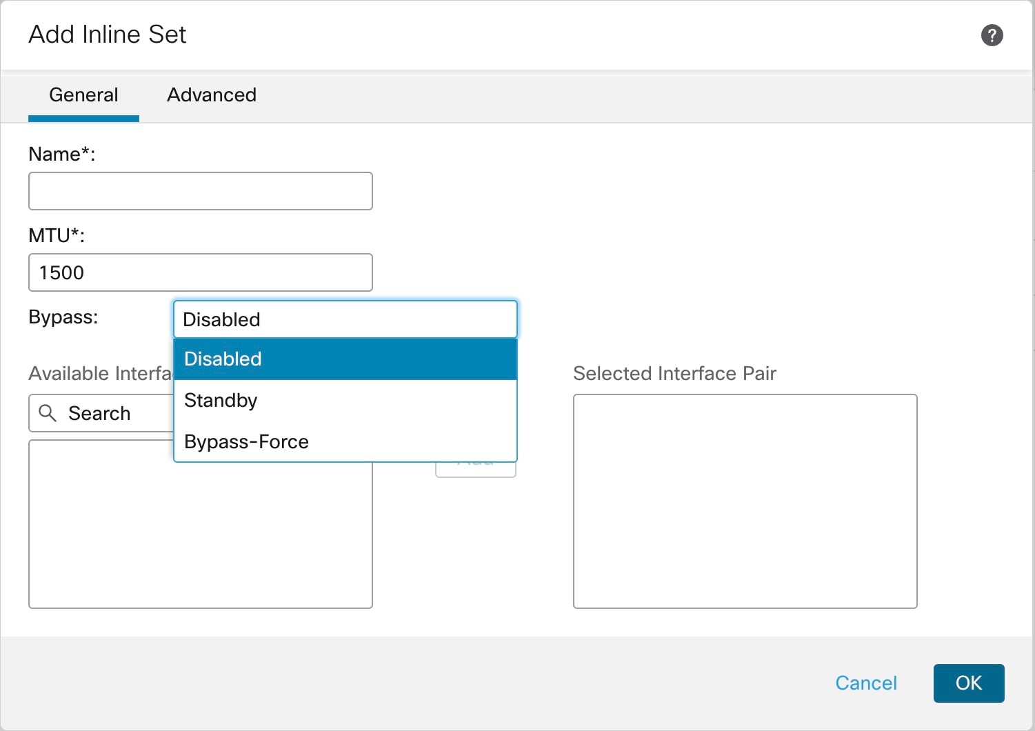
The Add Inline Set dialog box appears with General selected.

Step 13

In the Name field, enter a name for the set.

Step 14

(Optional) Change the MTU to enable jumbo frames.

For inline sets, the MTU setting is not used. However, the jumbo frame setting is relevant to inline sets; jumbo frames enable the inline interfaces to receive packets up to 9000 bytes. To enable jumbo frames, you must set the MTU of any interface on the device above 1500 bytes.

Step 15

Configure Hardware Bypass.

Note


Do not enable Bypass and Propagate Link State for the same inline set.

  1. For the Bypass mode, choose one of the following options:

    • Disabled—Set Hardware Bypass to disabled for interfaces where Hardware Bypass is supported, or use interfaces where Hardware Bypass is not supported.

    • Standby—Set Hardware Bypass to the standby state on supported interfaces. Only pairs of Hardware Bypass interfaces are shown. In the standby state, the interfaces remain in normal operation until there is a trigger event.

    • Bypass-Force—Manually forces the interface pair to go into a bypass state. Inline Sets shows Yes for any interface pairs that are in Bypass-Force mode.

  2. In the Available Interfaces Pairs area, click a pair and then click Add to move it to the Selected Interface Pair area.

    All possible pairings between named and enabled interfaces with the mode set to None show in this area.

Step 16

(Optional) Click Advanced to set the following optional parameters:

  • Tap Mode—Set to inline tap mode.

    Note that you cannot enable this option and strict TCP enforcement on the same inline set.

    Note


    If you need to enable or disable the Tap mode, you should do so during a maintenance window. Changing the mode while the device is passing traffic can cause traffic disruption.

    Note


    Tap mode significantly impacts the FTD performance, depending on the traffic.

  • Propagate Link State—Configure link state propagation.

    Link state propagation automatically brings down the second interface in the inline interface pair when one of the interfaces in an inline set goes down. When the downed interface comes back up, the second interface automatically comes back up, also. In other words, if the link state of one interface changes, the device senses the change and updates the link state of the other interface to match it. Note that devices require up to 4 seconds to propagate link state changes. Link state propagation is especially useful in resilient network environments where routers are configured to reroute traffic automatically around network devices that are in a failure state.

    Note


    Do not enable Bypass and Propagate Link State for the same inline set.

    Do not enable Propagate Link State when using clustering.

  • Snort Fail Open—Enable or disable either or both of the Busy and Down options if you want new and existing traffic to pass without inspection (enabled) or drop (disabled) when the Snort process is busy or down.

    By default, traffic passes without inspection when the Snort process is down, and drops when it is busy.

    When the Snort process is:

    • Busy—It cannot process traffic fast enough because traffic buffers are full, indicating that there is more traffic than the device can handle, or because of other software resource issues.

    • Down—It is restarting because you deployed a configuration that requires it to restart. See Configurations that Restart the Snort Process When Deployed or Activated.

    When the Snort process is down and comes back up, it inspects new connections. To prevent false positives and false negatives, it does not inspect existing connections on inline, routed, or transparent interfaces because initial session information might have been lost while it was down.

    Note


    When Snort fails open, features that rely on the Snort process do not function. These include application control and deep inspection. The system performs only basic access control using simple, easily determined transport and network layer characteristics.

    Note


    The Strict TCP Enforcement option is not supported.

Step 17

Click Interfaces.

Step 18

Click Edit (edit icon) for one of the member interfaces.

Step 19

From the Security Zone drop-down list, choose a security zone or add a new one by clicking New.

You can only set the zone after you add the interface to the inline set; adding it to an inline set configures the mode to Inline and lets you choose inline-type security zones.

Step 20

Click OK.

Step 21

Set the security zone for the second interface.

Step 22

Click Save.

You can now go to Deploy > Deployment and deploy the policy to assigned devices. The changes are not active until you deploy them.


History for Inline Sets and Passive Interfaces

Feature

Minimum FMC

Minimum FTD

Details

Synchronization between the FTD operational link state and the physical link state for the Firepower 4100/9300

6.7

Any

The Firepower 4100/9300 chassis can now synchronize the FTD operational link state with the physical link state for data interfaces. Currently, interfaces will be in an Up state as long as the FXOS admin state is up and the physical link state is up. The FTD application interface admin state is not considered. Without synchronization from FTD, data interfaces can be in an Up state physically before the FTD application has completely come online, for example, or can stay Up for a period of time after you initiate a shutdown. For inline sets, this state mismatch can result in dropped packets because external routers may start sending traffic to the FTD before the FTD can handle it. This feature is disabled by default, and can be enabled per logical device in FXOS.

Note


This feature is not supported for clustering, container instances, or FTD with a Radware vDP decorator. It is also not supported for ASA.

New/Modified Firepower Chassis Manager screens: Logical Devices > Enable Link State

New/Modified FXOS commands: set link-state-sync enabled, show interface expand detail

Supported platforms: Firepower 4100/9300

Hardware bypass support on the Firepower 2130 and 2140 for supported network modules

6.3.0

Any

The Firepower 2130 and 2140 now support hardware bypass functionality when using the hardware bypass network modules.

New/Modified screens:

Devices > Device Management > Interfaces > Edit Physical Interface

Supported platforms: Firepower 2130 and 2140

Support for EtherChannels in FTD inline sets or passive interface

6.2.0

Any

You can now use EtherChannels in a FTD inline set or passive interface.

Hardware bypass support on the Firepower 4100/9300 for supported network modules

6.1.0

Any

Hardware Bypass ensures that traffic continues to flow between an inline interface pair during a power outage. This feature can be used to maintain network connectivity in the case of software or hardware failures.

New/Modified screens:

Devices > Device Management > Interfaces > Edit Physical Interface

Supported platforms: Firepower 4100/9300

Inline set link state propagation support for the FTD

6.1.0

Any

When you configure an inline set in the FTD application and enable link state propagation, the FTD sends inline set membership to the FXOS chassis. Link state propagation means that the chassis automatically brings down the second interface in the inline interface pair when one of the interfaces in an inline set goes down.

New/Modified FXOS commands: show fault |grep link-down, show interface detail

Supported platforms: Firepower 4100/9300, Firepower 2100 (6.2.1 and later)