Diameter Configuration

Diameter Configuration

The Diameter Configuration section allows for the configuration of the diameter plug-in. We recommend configuring the diameter plug-in at system level.

At System Level

In order to define a Diameter Configuration at system level, you need to perform the following steps:

  1. Login into Policy Builder.
  2. Select Reference Data tab.
  3. From the left pane, select Systems.
  4. Select and expand your system name.
  5. Select Plugin Configurations.
  6. Select Diameter Configuration.

At Cluster Level

In order to define a Diameter Configuration at cluster level you need to perform the following steps:

  1. Log in into Policy Builder.
  2. Select Reference Data tab.
  3. From the left pane, select Systems.
  4. Select and expand your system name.
  5. Select and expand your cluster name. If no cluster has been created, create one by selecting the Cluster action.

  6. Select Plugin Configurations.
  7. Select Diameter Configuration.

The following parameters can be configured under Diameter Configuration.

Table 1. Diameter Configuration Parameters

Parameter

Description

Default Gx Stale Session Timer Minutes

This timer is armed every time a message is received or sent for any given Gx session. When the timer expires (or more precisely within the next minute after the timer expires) a Gx RAR having the Re-Auth-Request-Type AVP set to AUTHORIZE_ONLY (0) message is triggered for that Gx session. If a Gx RAA is received having Result-Code AVP value set to DIAMETER_UNKNOWN_SESSION_ID (5002) or DIAMETER_UNABLE_TO_COMPLY (5012) the Gx session is deemed as stale and removed from the PCRF internal database. On any activity over Gx interface (RAR/CCR) the timer is reset.

Default value is 180 minutes.

Note

 
  • This timer unit is minute.
  • Stale Gx session removal triggers the PCRF session termination procedure for any other diameter sessions that were bound to the Gx session.

Use V9 Event Trigger Mapping

This option allows for a different set of list of valid values and their interpretation to be used for the Event-Trigger enumerated AVP in order to accommodate the change that occurred in the Gx specification between 3GPP TS 29.212 v9.5 (and prior) and 3GPP TS 29.212 v9.7 (and following including v10 v11 and v12). Default value is checked.

List of valid values is provided in Table 2.

Note

 
  • The Event-Trigger AVP list of valid values and their interpretation defined in 3GPP TS 29.212 v9.6 is not supported.
  • Use V9 Event Trigger Mapping checked uses 3GPP TS 29.212 v9.5 as a reference while 3GPP TS 29.212 v110.10 is used as a reference when not checked.

Rel8 Usage Monitoring Supported

This option allows for the Gx usage monitoring feature to be supported even when the PCEF advertises support for Rel8 feature under Supported-Features AVP in Gx CCR-i.

Default value is checked.

Rel15 Ext Bw Nr Supported

When checked, it enables the support for 3GPP Rel-15 Extended BW-NR feature. PCRF sends response to AF/PCEF with Rel-15 Extended BW-NR feature bit set when the feature is enabled and AF/PCEF has also set the bit in the request message. PCRF sends extended QoS AVPs only if the configuration is enabled.

When unchecked, it disabled the support for 3GPP Rel-15 Extended BW-NR feature.

Default value is unchecked (disabled).

Stale Session Configuration

When a new row is added in “Stale Session Configuration” table the default value for the GX_TGPP SD_V11 and SY_V11 Stale session timer is 180 minutes.

Note


The maximum value allowed for the Stale Session Timer parameter is 35000 minutes.

If GX_TGPP Stale Session Timer value is not configured in this table, then the value is selected from the retained/old variable “Default Gx Stale Session Timer Minutes”.

If there are multiple values configured against any interface then the lowest among all would be considered as the stale session timer.

DRMP Prioritization

When enabled allows you to configure different message processing priorities based on the DRMP value received in the incoming request.

  • Default Inbound Priority - The default inbound priority value.

  • Inbound DRMP Prioritization

    • DRMP - DRMP AVP value in the incoming request.

    • Priority - Priority value assigned to the incoming message. Based on this value the message processing is prioritized. Higher Priority messages are be processed first compared to lower priority messages.


Note


If Gx stale session timer is set for both “Default Gx Stale Session timer Minutes” and “Stale Session Configuration” then the value configured Under “Stale Session Configuration” would take the precedence.


Table 2. Use V9 Event Trigger Mapping Valid Values

Interpretation - Use V9 Event Trigger Mapping is checked

Value

Interpretation - Use V9 Event Trigger Mapping is not checked

SGSN_CHANGE

0

SGSN_CHANGE

QOS_CHANGE

1

QOS_CHANGE

RAT_CHANGE

2

RAT_CHANGE

TFT_CHANGE

3

TFT_CHANGE

PLMN_CHANGE

4

PLMN_CHANGE

LOSS_OF_BEARER

5

LOSS_OF_BEARER

RECOVERY_OF_BEARER

6

RECOVERY_OF_BEARER

IP_CAN_CHANGE

7

IP_CAN_CHANGE

QOS_CHANGE_EXCEEDING

_AUTHORIZATION

11

QOS_CHANGE_EXCEEDING

_AUTHORIZATION

RAI_CHANGE

12

RAI_CHANGE

USER_LOCATION_CHANGE

13

USER_LOCATION_CHANGE

NO_EVENT_TRIGGERS

14

NO_EVENT_TRIGGERS

OUT_OF_CREDIT

15

OUT_OF_CREDIT

REALLOCATION_OF_CREDIT

16

REALLOCATION_OF_CREDIT

REVALIDATION_TIMEOUT

17

REVALIDATION_TIMEOUT

UE_IP_ADDRESS_ALLOCATE

18

UE_IP_ADDRESS_ALLOCATE

UE_IP_ADDRESS_RELEASE

19

UE_IP_ADDRESS_RELEASE

DEFAULT_EPS_BEARER

_QOS_CHANGE

20

DEFAULT_EPS_BEARER

_QOS_CHANGE

AN_GW_CHANGE

21

AN_GW_CHANGE

SUCCESSFUL_RESOURCE

_ALLOCATION

22

SUCCESSFUL_RESOURCE

_ALLOCATION

RESOURCE_MODIFICATION

_REQUEST

23

RESOURCE_MODIFICATION

_REQUEST

PGW_TRACE_CONTROL

24

PGW_TRACE_CONTROL

UE_TIME_ZONE_CHANGE

25

UE_TIME_ZONE_CHANGE

USAGE_REPORT

26

TAI_CHANGE

TAI_CHANGE

27

ECGI_CHANGE

ECGI_CHANGE

28

CHARGING_CORRELATION

_EXCHANGE

CHARGING_CORRELATION

_EXCHANGE

29

APN_AMBR_MODIFICATION

_FAILURE

USER_CSG_INFORMATION

_CHANGE

30

USER_CSG_INFORMATION

_CHANGE

DEFAULT_EPS_BEARER

_QOS_MODIFICATION_FAILURE

31

NA

NA

33

USAGE_REPORT

34

DEFAULT_EPS_BEARER

_QOS_MODIFICATION_FAILURE

35

USER_CSG_HYBRID

_SUBSCRIBED_INFORMATION

_CHANGE

36

USER_CSG_HYBRID

_UNSUBSCRIBED

_INFORMATION_CHANGE

37

ROUTING_RULE_CHANGE

39

APPLICATION_START

40

APPLICATION_STOP

42

CS_TO_PS_HANDOVER

43

UE_LOCAL_IP_

ADDRESS_CHANGE

44

HENB_LOCAL_IP_

ADDRESS_CHANGE

45

ACCESS_NETWORK_

INFO_REPORT

Inbound Message Overload Handling

This feature provides a mechanism for the OAM (PCRF) protection when the configured value of handling incoming messages exceeds. It provides a way to prioritize the incoming messages and selectively process them.

The following parameters can be configured under Inbound Message Overload Handling window:

Table 3. Inbound Message Overload Handling Parameters

Parameter

Description

Default Priority

Default priority to be assigned to an incoming message if no specific priority is defined in the Message Handling Rules table.

Default value is 0.

Message Sla Ms

Service Level Agreement (SLA) in milliseconds, defines the number of milliseconds that are associated with an incoming event or message within which Policy Director (load balancer) has to submit it to Policy Server (QNS) for processing. In case the configured duration times out, the Default Discard Behavior is applied.

Maximum time (in millisec) that a message has in an inbound message handling queue waiting for a worker thread. Configuring this value avoids processing a message to time out by a remote peer.

An SLA time that is too large can result in wasted processing on messages already timed out on a remote peer (i.e. PGW) and creation of stale sessions.

An SLA time that is too small can result in dropping the messages that could have been successfully processed.

Default value is 1500 ms.

Note


The value must be less than timeout configured at Gateway.

If you have not selected Inbound Message Overload Handling check box under Diameter Configuration, you can define inboundMessageSlaMs and inboundMessageQueueSize in /etc/broadhop/qns.conf file. If inboundMessageSlaMs is not defined in qns.conf file, then default value of 9000 is used.

Example: -DinboundMessageSlaMs=2000

After modifying the configuration on Cluster Manager execute reinit.sh or copytoall.sh scripts for applying the changes on all VMs as described in the CPS Installation Guide for VMware for this release.

If you select Inbound Message Overload Handling check box under Diameter Configuration, then the value you configured in Policy Builder is used.

The "Message Sla Ms" time out configuration value should be less than the timeout value in PGW or PCSF.

Inbound Message Queue Size

Number of messages waiting to be processed before the inbound overload feature is activated.

Default value is 1000.

If Inbound Message Overload Handling check box is not selected under Diameter Configuration, define inboundMessageSlaMs and inboundMessageQueueSize in /etc/broadhop/qns.conf file. If inboundMessageQueueSize is not defined in qns.conf file, then default value of 1000 is used.

Example: -DinboundMessageQueueSize=5000

After modifying the configuration on Cluster Manager execute reinit.sh or copytoall.sh scripts for applying the changes on all VMs as described in the CPS Installation Guide for VMware for this release.

If InboundMessage Overload Handling check box is selected under Diameter Configuration, then the value you configured in Policy Builder is used.

Note


It is recommended not to increase this queue size beyond the default value. This queue size is applicable per Policy Server (qns) node.

Configure the message queue size to allow buffering for a burst of messages that can be processed before SLA expiry. A queue size that is too large consumes memory resources. A queue size that is too small drops messages.

Configure this parameter help to prevent unnecessary consumption of memory resources for messages that cannot be processed in time.

Default Instance Rate Limit

Use this parameter to trigger the overload protection handling. If this is configured to value x TPS, then whenever x exceeds CPS applies message handling rules to additional requests. 0 (default) TPS indicates no limit.

Note


It is recommended to use the default value to avoid limit on the performance of Policy Server (QNS).

Default value is 0.

Gx Emergency Message Priority

Default priority assigned to messages related to an emergency session.

This parameter categorizes Gx messages as emergency priority based on APN. Emergency priority messages are queued ahead of non-emergency service messages for quick servicing and prevent them from being dropped using overload controls.

If the queue is full, the lowest-priority message is dropped.

Recommended Value: Regex match of SOS APNs for emergency priority classification. Set emergency priority to highest for priority handling in Policy Server (QNS) Inbound Message Queue.

Default value is 1.

Default Discard Behavior

Default behavior to be applied to an incoming message if no specific priority is defined in the Message Handling Rules table.

  • MESSAGE_DROP: Discards the request.

  • DIAMETER_TOO_BUSY: Sends a response message having Result-Code AVP value set to DIAMETER_TOO_BUSY (3004)

Default value is MESSAGE_DROP.

Apply Discard Behavior For Emergency Messages

Indicates if Emergency Messages can be discarded under overload conditions.

Default value is not checked.

Rx Message Prioritization

Defines Rx eMPS message handling priority under overload condition based on Rx AAR MPS-Identifier and Reservation-Priority AVPs.

When Rx Message Prioritization is enabled and if MPS-Identifier and Reservation-Priority AVPs are available in Rx_AAR, then the messages are not dropped even in overload condition. Depending on the message Priority defined in table, the message can be moved to the front in the inbound queue.

This feature indicates that, the Rx_AAR is prioritized based on MPS-Identifier and Reservation-Priority AVPs configured only. If the inbound message doesn’t have these parameters included, the message is not prioritized. Prioritization of messages is only applicable to incoming request messages.

For more information on parameters, see Table 2.

Message Handling Rules

Defines specific inbound message overload handling rules based on different criteria. For more information, see Table 3.


Note


If you do not select Inbound Message Overload Handling check box in Diameter Configuration, you can define inboundMessageSlaMs and inboundMessageQueueSize in /etc/broadhop/qns.conf file. For more information, see Table 1.


Table 4. Rx Message Prioritization Parameters

Parameter

Description

MPS Identifier

MPS-Identifier indicates that an AF session relates to an MPS session. It contains the national variant for MPS service name.

MPS-Identifier value = <NS (National Security) Specific To Deployment>

Reservation Priority

The AF specifies the Reservation-Priority AVP at request level in the AA-Request in order to assign a priority to the AF session as well as specify the Reservation-Priority AVP at the media-component-description AVP level to assign a priority to the IP flow.

The Reservation-Priority AVP available at the request level only is used under Rx Message Prioritization table.

Range: Any number

Example: 10

Priority

A user defined priority based on MPS-Identifier and Reservation-Priority combination. Make sure that the Message priority defined in Rx Message Prioritization table and should be unique per row.

Higher Priority messages are processed first compared to lower priority messages.

Range: Any number (User priority)

Example: 10


Note


Rx Message Prioritization table does not supports multiple values in a single column. Rx Message Prioritization table must be configured with unique combination for each row.


Table 5. Message Handling Rules Parameters

Parameter Type

Attribute

Description

INPUT

Diameter Client

(Optional) This field is used to configure different priorities for different clients based on realms. For more information, see Diameter Clients.

Protocol

Specific application id value to be used for scoring. This value is used to match Auth-Application-Id AVP value. For more information, see Table 4.

Command Code

Specific command code value to be used for scoring. This value is used to match the Command-Code field. These command codes map to different types of Diameter messages (CCR = 272 RAR = 258 etc).

Default value is 0.

Request Type

Specific request type value to be used for scoring. This value should match the value of the CC-Request-Type AVP for Gx CCR messages.

  • 0: Request Type not used for scoring

  • 1: INITIAL_REQUEST (1)

  • 2: UPDATE_REQUEST (2)

  • 3: TERMINATION_REQUEST (3)

Default value is 0.

Request type should match the value of the Rx-Request-Type AVP for Rx AAR messages.

  • 0 INITIAL_REQUEST (0)

  • 1 UPDATE_REQUEST (1)

Request type should match the value of SL-Request-Type AVP for Sy SLR messages. The possible values are:

  • INITIAL_REQUEST (0)

  • INTERMEDIATE_REQUEST (1)

It has to be configured to zero if the incoming message does not have a request type AVP. For example, Rx STR does not have a request type AVP or Rx-Request-Type AVP is unavailable in Rx AAR as it is not a mandatory AVP per 3GPP TS 29.214.

OUTPUT

Priority

Priority value assigned to the message. Higher numerical value has the higher priority.

Default value is 0.

For example, 10, 20, 100, 200, 300, 500 and so on.

Per Instance Tps

Transactions per second limit per process. This value is the TPS that these messages are limited to. Note that this is per CPS process so if there are 20 Policy Server VM's with 1 Policy Server java process the total TPS is this number x 20.

The actual system's transaction per second limit can be calculated using the following formula:

Per Instance Tps x Number of instances per VM x Number of VMs.

Default value is 0.

For example, 1000, 2000, 5000 and so on.

Discard Behavior

Behavior to be applied to an incoming message.

  • MESSAGE_DROP: Discards the request.

  • DIAMETER_TOO_BUSY: Sends a response message having Result-Code AVP value configured to DIAMETER_TOO_BUSY (3004).

Default value is MESSAGE_DROP.


Note


A Diameter message even if prioritized under an overload condition could be dropped by CPS if one of the following conditions are met:

  • Per Instance TPS configured limit exceeds except for Gx Emergency/Rx eMPS/DRMP calls.

  • Inbound Message Queue size exceeds for a message.

  • Inbound Message Sla Ms exceeds for a message.


Table 6. Protocols

Attribute

Description

GY_V8

Standard Gy application as per 3GPP TS 32.299

GX_SCE

Custom Gx implementation

RF_V10

Not supported

RF_VERIZON

Not supported

RX_TGPP

Standard Rx application as per 3GPP TS 29.214

SH_TGPP

Standard Sh application as per 3GPP TS 29.329

SY_V11

Standard Sy application as per 3GPP TS 29.219

SD_V11

Standard Sd application as per 3GPP TS 29.212

GX_TGPP (default)

Standard Gx application as per 3GPP TS 29.212

GXX_TGPP

Not supported

RX_CLIENT

Local MINE adapter

GY_V8_PROXY

Gy proxy implementation as per RFC 3588

GX_TGPP_PROXY

Gx proxy implementation as per RFC 3588

SY_TGPP_PROXY

Sy proxy implementation as per RFC 3588

SY_OCS

Sy Proxy from OAM (PCRF) end

GY_RECHARGE_WALLET

Support Gy client functionality with external OCS (ECUR model only)

SY_PRIME

Custom Sy implementation as per RFC 3588

RX_TGPP_PROXY

Rx proxy implementation as per RFC 3588

SY_OCS_SERVER

OCS Sy server endpoint conforming to 3GPP TS 29.219


Note


When a Diameter Stack with a diameter realm is imported with unassigned protocol, the default value of GX_TGPP is used.


Stale Session Message Handling Configuration

This feature enables CPS application to act according to the configuration when request processing crosses the given SLA time period for the incoming request. When the feature is enabled the request or responses which are crossing the configured SLA are dropped.

By default, stale session message handling is disabled. To enable this configuration, you need to configure the Stale Session Message Handling configuration in Policy Builder and publish the changes.


Note


The configuration changes are reflected at the run time and no process restart is required.


The following table describes the parameters under Stale Session Message Handling Configuration.

Table 7. Stale Session Message Handling Configuration Parameters

Parameter

Description

End to End Sla Ms

Maximum time in milliseconds the CPS system must take for request processing. The request processing time for this value must be LB > QNS > DB > QNS > LB round trip.

Default: 2000 ms

Include Request LB queue time in QNS SLA

When checked, LB - QNS request queue time is considered in QNS SLA when enabled.

Default value is disabled.


Note


  • The End To End SLA value must always be greater than the existing QNS-SLA configured in the qns.conf file.

  • All the Policy Director (LB) and Policy Server (QNS) VMs need to be in time sync to ensure that the functionality of this feature works as expected.


Next Hop Routing

This feature provides support for inter-working with a DRA that is not configured in topology hiding mode. This is required because while the DRA advertises its own origin host and realm values when the diameter connection is established all the diameter application messages feature the actual host's origin host and realm (i.e. PCEF TDF AF). PCRF needs a way to figure out which particular DRA connection should use in order to deliver a message to the desired host.

While selecting the peer that is used to deliver the request (with or without using the Next Hop Routes table) load balancing across the peers having the same rating is done. Load balancing starts from the peers having highest rating and covers all the peers in a round robin manner. If none is UP load balancing is tried with the peers having the second highest rating and again covers all the peers in a round robin manner and so on.


Note


Next Hop Routes table is used only for PCRF initiated requests. The response messages for any incoming request is always delivered on the same connection where the request was received or not delivered at all. This is in order to avoid asymmetric routes.


The DRA should explicitly advertise support for a Diameter application other than Relay. The Relay application having Application Identifier 0xffffffff is not supported.

The following parameters can be configured under Next Hop Routing table:

Table 8. Next Hop Routing Parameters

Parameter

Description

Next Hop Realm

DRA realm name as received in Origin-Realm AVP in CER or CEA message.

Note


All the next hop realms (Next Hop Realm) should match the Origin-Realm AVP value in the incoming CER/CEA message.

Next Hop Hosts

DRA hosts name list as received in Origin-Host AVP in CER or CEA message.

Note


All the next hop host names (Next Hop Hosts) should match the Origin-Host AVP value value in the incoming CER/CEA message.

Application Id

Diameter application id advertised as being supported by the DRA. It contains information that identifies the particular service that the service session belongs to.

Destination Realms Pattern

Actual destination realm name pattern as received in Origin-Realm AVP in AAR message. The pattern needs to follow the standard Java regular expression syntax described here.

Destination Host Pattern

Actual destination host name pattern as received in Origin-Host AVP in AAR message. The pattern needs to follow standard Java pattern conventions. The pattern needs to follow the standard Java regular expression syntax described here.

While populating the Next Hop Routes table, we recommend that you create only one entry for each Next Hop Realm value - Application Id value pair while all the DRA host names are provided as a list under Next Hop Hosts field. This is not a requirement though.


Note


The order in which the DRA hosts are provisioned in the Next Hop Hosts field for any given next hop route is not relevant. The DRA host having the highest rating (priority) value is used. In case multiple hosts have the same rating one is randomly selected. Refer to Diameter Stack Configuration for more details about host rating. Outbound realm rating of next hop is not considered except for SY_PRIME.


CPS supports grouping of realms and application identifiers using wildcarding and assigns it to a group of next hop peers. CPS routes outgoing messages by selecting the peer with highest priority.

An example configuration for Grouping and Wildcarding in the Next Hop Routing table is shown below:

Figure 1. Grouping and Wildcarding in the Next Hop Routing Table

Destination Realm and Destination Hosts are used to map with the Peer configuration as defined in the Diameter Stack. The figure given below shows the mapping of the message containing the Realm from a peer to a protocol or interface. For more information on peer configuration refer to Diameter Stack Configuration.

Figure 2. Rating

Message Timeout and Retry Configuration

Message Timeout and Retry Configuration table can be configured under Diameter Configuration plug-in in Policy Builder.

This table allows for the configuration of different message timeout value and retry behavior using the combination of Application Id, Command Code and (experimental) result code parameters.


Note


Sh Interface (Auth-Application-Id 16777217) message retry information can be configured using:

  • Message Timeout and Retry Configuration table

  • Setting Up Additional Profile Data

Only one of the two retry configuration options should be used for Sh Interface.


The following parameters can be configured in the Message Timeouts and Retry Configuration table.

Table 9. Message Timeout and Retry Configuration Parameters

Parameter

Description

Application Id

The Diameter Application ID (Auth-Application-Id) on the message which is to be retired.

Default: 0

Command Code

The Diameter command code of the message which is to be retried.

Default: 0

Result Code

This is the result code received in the diameter response for which the user wants to retry. The values configured should be a valid diameter result code value or an experimental result code value. For example, 3002 (DIAMETER_UNABLE_TO_DELIVER) received in RAA.

Permanent failure result codes 5xxx and successful result codes 2xxx should not be configured (where, x denotes a valid number).

However, if configured, CPS retries for it.

Note


For retry on timeout, the result code should be configured as 7000.

Default: 0

Is Experimental

If this check-box is selected, it means that the value configured in the Result Code column is an Experimental-Result-Code value.

This is necessary because there are few values which are the same for both experimental-result-code and result-code.

Default: Not selected

Action

The action for the CPS platform to take after the Diameter Response is received. The options are Retry or None.

  • Retry - CPS retries the request message identified by the value in the command code column depending on the retry count configured in Retry Count column.

  • None - No retry.

Default: None

Action Timer (Ms)

The amount of time in milliseconds for CPS to wait before doing a retry. It is the wait time between retries. CPS doesn't retry immediately and drops all the stress on the system1.

Default: 0

Retry Count

The number of times to retry when the action is “Retry”.

Note


This retry count does not include the initial attempt made by CPS.

Default: 1

Retry on Alternate Node

Configures CPS to retry on any alternate peer configured in Policy Builder.

Default: Not selected

Backoff Algorithm

The back-off algorithm used while determining the actual delay between retry attempts. Currently, only one option (CONSTANT_INTERVAL) is supported.

  • LINEAR_INTERVAL: Causes the configured retry interval to increase linearity with each attempt using the formula retry interval = Action Timer (Ms) x current retry attempt number.

    For example, Action=Retry, Action Timer (Ms)=200, Retry Count=3, Backoff Algorithmm=LINEAR_INTERVAL will trigger the first retry after 200 x 1 = 200 ms, the second retry after 200x2 = 400 ms, the third retry after 200x3 = 600ms

  • CONSTANT_INTERVAL: Causes the configured retry interval to be used (without any change) for delay for all retry attempts (other options like exponential back-off where retry interval increases exponentially are currently not supported/implemented).

Default: CONSTANT_INTERVAL

1

If the timeout and retry count is not configured then the default values (diameter.default.timeout.ms and diameter.default.retry.count) defined in /etc/broadhop/qns.conf are used.

The diameter.default.timeout.ms and diameter.default.retry.count parameters configured in qns.conf file are taken into consideration only in case of timeout (result code = 7000) and do not impact the behavior in any other case (result code other than 7000).

If no values are defined in the qns.conf file, then the default values of diameter.default.timeout.ms=3000 and diameter.default.retry.count=1 are used. If Result Code = 7000 is defined in the Message and Retry Configuration table in Policy Builder, then this configuration takes precedence over qns.conf file parameters.

Result Code Based Action Configuration

CPS can be configured to take specific action over Gx and Sy based on response received on Sy/Sd interfaces. CPS can be configured to continue (default) terminate or re-initiate the session.

Figure 3. Result Code Based Action

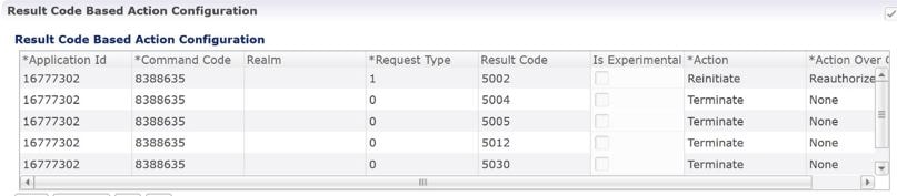
The following parameters can be configured in the Result Code Based Action Configuration table.

Table 10. Result Code Based Action Configuration

Parameter

Description

Application Id

The diameter interface in numeric format (Auth-Application-Id) on which the message is received. For example Sy (16777302) and Sd (16777303).

Currently only Sd and Sy interfaces are supported.

Default: 0

Command Code

The diameter message type. For example SLR (8388635) in case of Sy and RAR (258) in case of Sd.

Default: 0

Realm

New key added as Sy client realm. If the realm value is not specified, then the realm key is not be considered (CPS only performs action on key applicationid:commadcode:realm:requestType:resultcode ).

Request Type

The request type of the message for Sy interface. For example INITIAL_REQUEST (0) INTERMEDIATE_REQUEST (1). For Sd Request Type is not valid.

Default: 0

Result Code

The result-code received in the response for which the action over Gx and/or Sy/Sd is to be taken.

Default: 0

Is Experimental

If this check-box is selected, it means that the value configured in the Result Code column is an Experimental-Result-Code value.

This is necessary because there are few values which are the same for both experimental-result-code and result-code.

Default: Not selected

Action

The action to be taken over the Sy/Sd interface when the response is received. Possible actions are Continue/Terminate/Reinitiate.

  • Continue (default) In case of Continue CPS just continues with the session and does not clear the session from the DB.

  • Terminate (for Sd) In case of Terminate CPS removes the session from database after triggering a Session Removal RAR over Sd interface.

    Terminate (for Sy) In case of Terminate CPS removes the session from database after triggering a Session Removal STR over Sy interface.

  • Reinitiate (for Sd) In case of Reinitiate CPS first triggers a Session Removal RAR over Sd interface. Once we receive Sd RAR response (any result-code) CPS removes the old session and triggers creation of a new session by sending out a TSR towards TDF.

    Reinitiate (for Sy) In case of Reinitiate CPS first triggers a Session Removal STR over Sy interface. Once we receive Sy STR response (any result-code) CPS removes the old session and triggers creation of a new session by sending out SLR towards OCS.

  • Re-Initiate Action Timer (Ms): The amount of time in milliseconds for CPS to wait before performing a retry. It is the wait time between retries.

    Note

     
    This configuration works in accordance with the Next Evaluation Timer. Hence, there will be a minute delay in Message generation. Default: 0
  • Re-Initiate Retry Count: The number of times to retry when the action is ?Retry?.

    Note

     
    The retry count does not include the initial attempt made by CPS. Default: 0
  • Backoff Algorithm: The backoff algorithm is used for determining the actual delay between retry attempts. Currently, only one option (CONSTANT_INTERVAL) is supported.

  • LINEAR_INTERVAL: Causes the configured retry interval to increase linearity with each attempt using the formula

    retry interval = Action Timer (Ms) x current retry attempt number

    For example, Action=Retry, Action Timer (Ms)=200, Retry Count=3, Backoff Algorithm=LINEAR_INTERVAL will trigger the first retry after 200 x 1 = 200 ms, the second retry after 200x2 = 400 ms, the third retry after 200x3 = 600ms.

  • CONSTANT_INTERVAL: Causes the configured retry interval to be used (without any change) for delay for all retry attempts.

    Note

     
    Other options such as exponential back-off where retry interval increases exponentially are currently not supported.

    Default: CONSTANT_INTERVAL

Action Over Gx

The action to be taken over the Gx interface when the response is received. Possible actions are None/Terminate/Reauthorize.

Currently Action over Gx is not supported for Sd RAR.

  • None (default): No action would be taken on Gx interface.

  • Terminate: In case of Terminate CPS would terminate the Gx session by sending a RAR with Session Release Cause. Also CPS would be sending STR which would then clear the corresponding Sy device session. If the action over Gx is TERMINATE the action over Sy does not matter as the Sy session would be terminated.

  • Reauthorize: In case of Reauthorize CPS would mark the Sy session as waiting for action over Gx and would mark corresponding Gx session as needing action over Gx as Re-Auth.

The Gx Network Device Manager would then perform the ReAuthorization by sending RAR over Gx interface. On receiving RAA the action over Sy interface would then be performed. If the Gx session is stale and we receive DIAMTER_UNKNOWN_SESSION_ID the Sy session would then be automatically terminated irrespective of the action configured on Sy interface.

Note


The actions TERMINATE and REAUTHORIZE over Gx does not work with SLA-Initial if the SLR is sent synchronously. In case the SLR is triggered synchronously and the action over Gx is configured as TERMINATE/REAUTH the CPS would log an error message and would continue the session. The synchronous/asynchronous sending of SLR can be configured in the SpendingLimitReport service configuration.

Message Buffering Configuration

When Gx features for OneGxRulePerFlow is enabled then the gateway triggers simultaneous Gx-CCR-Us for APPLICATION-START within a short time span. This causes a burst of CCR-U message on CPS. Because of the burst, CPS fails to process all the CCR-U message due to "cache out of date" errors and sends DIAMETER_UNABLE_TO_DELIVER errors to gateway. So in order to support the processing of all the CCR-U messages, Message Buffering Configuration can be used.

Message Buffering Configuration can be configured under Diameter Configuration plug-in in Policy Builder.

The following parameters can be configured under Message Buffering Configuration:

Table 11. Message Buffering Configuration Parameters

Parameter

Description

Buffer Timeout In Milliseconds

The time in milliseconds to hold the diameter messages in the buffer after the buffering has been triggered for a particular session ID.

Default value is 15 ms.

Max Buffered Messages Per session

Maximum number of messages that are held in the message buffer for a particular session ID.

Default value is 64.

Disable Early Processing

Disable the early processing of buffered message before the configured buffer-timeout (15 ms).

If the message buffering has started then CPS triggers an early timeout (after 5 ms) and check the buffer status. If the buffer has single message or contains messages without any holes (in correct sequence) then it sends the first message to Policy Server (qns) node for processing.

Default value is unchecked.

Allow Gaps In Buffer

Do not drop the messages from the message buffer when a hole/gap is detected while processing the buffered messages (i.e. after ordering the buffered message it detects that certain messages are missing).

Default value is unchecked.

Message Buffering Table

This table is used to specify the criteria for buffering the messages. CPS buffers only those messages that have a matching entry in this table. For more information on parameters, refer to Table 2.

Table 12. Message Buffering Table Parameters

Parameter

Description

Application Id

Application ID of the interface whose message are to be buffered. For example, 16777238 for Gx messages.

Command Code

Command code of the diameter message for the above application ID. For example, 272 for CCR messages.

Origin Realm Pattern

Origin-realm from the diameter request message to check for message buffering. It supports pattern matching as per the JAVA regular expression. This is an optional field and if not configured then CPS applies the configuration to any realm for the matching application ID and Command Code.

Origin Host Pattern

Origin-host from the diameter request message to check for message buffering. This is an optional field and if not configured then CPS applies the configuration to any host for the matching application ID and Command Code.

Note


In case of multiple entries for same application ID and command code combination, CPS matches the origin-realm and origin-host from the message with the realm and host patterns defined in the table and use the row that matches first.

Buffer Start Avp Code

Diameter AVP code for the AVP that would trigger the start for buffering the messages. For example, 1006 is the diameter AVP code for Event-Trigger AVP.

Note


Allowed parameters are of string type so that child AVP path can also be used.

For example, To give Charging-Rule-Report > Rule-Failure-Code, you have to mention '1018.1031' (where, 1018 is an AVP Code for 'Charging-Rule-Report' and 1031 is an AVP Code for 'Rule-Failure-Code').

All rows having same 'Application Id' and 'Command Code' should have same Order AVP Code and Order AVP Type.

CPS goes through all the rows one by one and verifies whether configured AVP exist in the incoming message and buffers the message accordingly.

Buffer Start Avp Type

A drop-down list to select the data-type of the AVP to trigger buffering of message. This is required for correctly extracting the AVP value.

Buffer Start Avp Value

The possible values for the diameter AVP for starting the buffering of message. List supported to configure multiple values.

Order Avp Code

The diameter AVP code for the AVP whose value can be used for sequencing/ordering the buffered message while sending them to Policy Server (qns) node for processing.

Order Avp Type

A drop-down list to select the type of the Order AVP for extracting its value.

CPS currently supports only numeric values for ordering the buffered messages.

Memory Impact

  • The memory usage of diameter endpoint process (qns process on lb) may be increased when it starts buffering messages for multiple sessions.

Configuration and Restrictions

  • Buffered messages are lost if the diameter-endpoint (qns process) on LB node goes down.

  • All the CCR-U messages in the burst are processed sequentially, that is, only after a CCA-U is sent out for a CCR-U message then the next CCR-U message is taken up for processing.

  • CPS initiated messages (for example, Gx RAR) are not considered for buffering and are sent out as they are triggered. Also, if terminate message (for example, Gx CCR-T) is received in between a message burst then CPS drops all further messages from the buffer after processing the terminate message.

  • As the buffered messages are processed sequentially the response time (towards PCEF) increases. For example, for a burst of 64 simultaneous CCR-U messages, CCA-U for the last message (that is, CCR-U message with highest sequence number) is after a duration of 64*20+15 ms (approx. 1300 ms).

  • The response time (towards PCEF) for normal messages (not received in a burst but matches the message buffering criteria) has an impact of at least 5 ms (the early processing time). For example, if CCR-U processing takes 20 ms then for a single user plane CCR-U message, the minimum response time is 25 ms.

  • If CPS receives negative response from Policy Server (qns) node while processing a buffered message then CPS stops processing the message buffer for that session and drops all further buffered messages.

  • While processing a buffered message if Policy Director (lb) node does not get a response from Policy Server (qns) node within the configured time (SLA) then it drops all the remaining messages from the message buffer of that session. The SLA time is calculated from the time the message was sent from Policy Director (lb) to Policy Server (qns) node and the time that the message spends while waiting for processing in the message buffer.

  • CPS checks only for 3GPP vendor ID while matching the diameter AVP code defined for Buffer start AVP and Order AVP. If vendor ID is not available in the received AVP then it is assumed to be of default 3GPP vendor ID.

  • While processing the buffered messages, if another burst of CCR-U messages is received then CPS appends those messages to the existing buffer. In doing so if the buffer size reaches the Max Buffered Messages per session then CPS drops those messages.

  • CPS maintains the order only for buffered messages. Order is not checked for messages across multiple message bursts for same session.

PolicyDRA Health Check

PolicyDRA Health Check is used to initiate a dummy AAR message that results in querying the binding database allowing the PCRF to take corrective action based on the response.

PolicyDRA Health Check is configured under Diameter Configuration plug-in in Policy Builder. Select PolicyDRA Health Check and Binding Db configuration to enable the feature.

The following parameters can be configured under PolicyDRA Health Check:

Table 13. PolicyDRA Health Check Configuration Parameters

Parameter

Description

Binding Db

When selected, it enables the feature.

When unselected, the feature is disabled.

  • Health Check Time Interval: Time interval in seconds when periodic AAR is sent.

    Note


    The Health Check Time Interval and Revalidation Time under RevalidationTime service configuration should not be configured with the same value.

    For more information on Revalidation Time, refer to RevalidationTime in Service Configuration Objects chapter.

  • Session Release T P S: Per Policy Server (QNS) Gx RAR (with session release cause) TPS when binding database is down.

    Default value is 0.

Alarm Config

When selected, it enables the generation of alarms or traps.

When unselected, the alarms are not generated.

  • Primary Ip Address: Primary database IP address where the alarm information is stored.

    Whenever PolicyDRA binding database down is detected i.e., when AAA comes with error result code, CPS generates a trap/notification/alarm. The generation time of this alarm is stored in the database configured. After the Alarm Clearance Interval, the trap/notification/alarm is cleared by CPS. In between this duration, CPS does not generate trap/notification/alarm on detection of binding database failure. Only one trap/notification/alarm is generated by CPS.

  • Secondary Ip Address: Secondary database IP address where the alarm information is stored.

  • Port: Port number of the database.

    Default value is 0.

  • Alarm Clearance Interval: Timer interval in seconds after which the alarm is cleared.

  • Policy Dra Resultcode: AAA result-codes for which alarms are generated.

  • Severity: Severity of the alarm.

    Default value is Critical.

Enable Proxy

When checked, it makes sure P-Bit is set and Destination-Host AVP is not set for the outgoing AAR messages for PAS Health check.

Default value is unchecked.


Note


To improve the performance when PolicyDRA Health Check is enabled, you must configure ‘RxClientSessionKey’ key as the Lookaside Key Prefix so that memcache is used and full database scan is avoided. This is highly recommended for higher capacity systems.


Diameter Messages Action on Threshold in LB

When Diameter Messages Action on Threshold in LB check box is enabled and Diameter Message Count Threshold for PD is configured with value greater than 0, the Policy Director processes keep track of messages being handled at process level and when number of messages being tracked crosses the configured Diameter Message Count Threshold for PD, the messages are dropped or responded with DiameterBusy.

Diameter Messages Action on Threshold in LB configuration is optional. When this configuration is not used, all the messages are sent from LB (Policy Director) to Policy Engines.

  • The following parameters can be configured under Diameter Messages Action on Threshold:

    Table 14. Diameter Messages Action on Threshold

    Parameter

    Description

    Diameter Interface

    Diameter Interface in Diameter message selected from drop-down list.

    Command Code

    Command code in Diameter message.

    When Command Code is set to 0, it applies to all Command Codes of the Application ID configured in the row.

    Request Type

    CCR Request type.

    Default value is 0.

    When Request Type is set to 0, it applies all the CCR Request types, namely Initial(1), Update(2) and Terminate(3). For non-CCR messages default 0 is must be set.

    Action

    What action to take when the Diameter message is received at LB (Policy Director) when outstanding Diameter messages have reached the Message Count Threshold.

    Possible Values: MESSAGE_DROP and DIAMETER_TOO_BUSY

    Default value is MESSAGE_DROP.

  • Diameter Message Count Threshold for PD: This value defines the maximum number of a Diameter Inbound/Outbound messages per PD (Policy Director) process from the table Diameter Messages Action on Threshold in LB. Default value is 0.

  • Max TPS per PD: Defines maximum TPS supported per PD process. Default value is 0.

  • Default Discard Behavior: Describes the action to be taken when a Diameter request message is received in LB and rate limiter acquire fails. Possible values include MESSAGE_DROP and DIAMETER_TOO_BUSY. Default value is MESSAGE_DROP.


    Note


    If DIAMETER_TOO_BUSY is selected from the drop-down list, at very high TPS, it can lead to higher CPU consumption on Policy Director (LB) VM. This can lead to performance degradation. Cisco recommends using MESSAGE_DROP.


Session Id Handling Configuration

Session Id Handling Configuration provides an option to parse part of the Diameter session ID attributes and store them in session AVP.

The following table describes parameters that can be configured under Session Id Handling Configuration.

Table 15. Session Id Handling Configuration

Parameter

Description

Diameter Interface

Diameter Interface DM for which the Session ID handling is required.

Input Regex

Provide an inverse regex to derive the new AVP.

Example: Consider the Session ID is pcef01.dstest01.2b4.gx;375030;1285311481;BB2001@MCC2001. To get the Gw_Version BB2001@MCC2001, write an inverse regex ".*;.*;.*;" which returns BB2001@MCC2001 as value.

Output Policy AVP Name

Policy derived AVP name to be stored.

Save to Session

Save the policy derived AVP to session.

Origin Realm

Origin-realm from the diameter request message to parse the session ID.

Origin Host

Origin-host from the diameter request message to parse the session ID.

Gx Offline Stale Session Cleanup


Important


This feature is only enabled for deployments with arbitervip running on pcrfclient VMs.


Stale session builds up due to network issues, timeout at PAS and so on. As a result CPS starts rejecting new sessions due to capacity or session license limit. The offline Stale Session cleanup helps to remove the stale sessions having duplicate IMSI and AON combination.

Execute the following command in the pcrfclient where the application is running to stop the application:

monit stop stale-session-cleaner-helper

Execute the following command in the pcrfclient where the application is not running to restart the application:

monit restart stale-session-cleaner-helper

The following table lists parameters in the /etc/broadhop/stale-session-cleaner/stale-session-cleaner.conf file:

Table 16. Gx Offline Stale Session Cleanup Configuration Parameters

Parameter

Description

-Dadmin.primary.host

VM name which hosts the primary member of the PCRF Admin replica-set.

Any sessionmgr VM names.

Default value is localhost.

Example: sessionmgr01

-Dadmin.secondary.host

VM name that hosts a secondary member of the PCRF Admin replica-set. If the primary Admin member fails, the Stale Session Cleaner tries to connect to this secondary member.

Any sessionmgr VM names.

Default value is localhost.

Example: sessionmgr02

-Dadmin.port

Port of the PCRF Admin replica-set.

Possible values can be Integers.

Default value is 27017.

Example: 27721

-Dmemcache.host

The Host on which memcache is running on.

Strings in the following format: <host>:<port>

Default value is localhost.

-Dmemcache.port

The Port number of memcache.

Possible values are Integers.

Default value is 11211.

-Dtps.per.shards

Maximum number of executions per second per shard.

Possible values are Integers.

Default value is 200.

-Dmongo.query.batch.size

Number of records in the results for each query to the Session replica-set.

Possible values are Integers.

Default value is 1000.

-Dfactor.count.audit.log

If the number of deleted sessions reaches a multiple of this parameter’s value, it performs audit log.

For example, if the parameter value is 100, then the deleted count is printed in the logs on 100 deletions, 200 deletions, 300 deletions, and so on.

Possible values are Integers.

Default value is 10000.

-Dsession.count.threshold

Specify the minimum count of session at which the utility triggers stale session cleanup.

Possible values are Integers.

Default value is 15000000.

-Dsession.threshold.timer

The frequency in minutes where utility monitors session threshold breach to start deletion of stale session.

Possible values are Integers.

Default value is 5.

-Dsession.cache.update.timer

The frequency in minutes where utility updates the latest session ID in the local cache. This parameter should be in the multiple of "session.threshold.timer."

Possible values are Integers.

Default value is 30.

-Dnumber.of.shards

Total number of shards for the Session replica-sets.

Possible values are Integers.

Default value is 80.

-Dlogback.configurationFile

The path to the log configuration file.

Any directory path with a logback file for the application.

Default value is /etc/broadhop/logback-stale-session-cleaner.xml.

Cleaning Stale Session


Important


This feature is only enabled for deployments with arbitervip running on pcrfclient VMs.

The services for the application are running on pcrfclient from first deployment, but the application does not start unless the arbitervip is present on the pcrfclient VM. The default value for admin database is 127.0.0.1. Application only starts to delete stale sessions when admin database is correctly configured.


Stale session build up due to network issues when CPS is processing bulk traffic. Stale sessions are observed when there is an increase in incoming request and timeouts are observed. Session replica-sets are piled-up with the sessions and once the session capacity limit is breached, CPS start rejecting new session requests.

The existence of stale sessions in session replica sets results in storage of duplicate sessions, i.e. multiple sessions from a subscriber UE to the same APN. This feature is to identify the duplicate sessions (match with same IMSI + APN) in regular intervals and keep the latest session and remove the older duplicate sessions to make sure that there is no additional overhead in call processing.


Note


Enabling/disabling this feature does not have any impact on existing stale session functionality.

This utility cleans the stale sessions without sending RARs to the gateway. This utility does not deletes corresponding records from SK database.


The following table lists parameters in the /etc/broadhop/stale-session-cleaner/stale-session-cleaner.conf file:

Table 17. Stale Session Cleanup Configuration Parameters

Parameter

Description

-Dadmin.primary.host

VM name which hosts the primary member of the PCRF admin replica-set.

Any sessionmgr VM names.

Default value is localhost.

Example: -Dadmin.primary.host=sessionmgr01

Possible Values: Primary Admin database name

-Dadmin.secondary.host

VM name that hosts a secondary member of the PCRF admin replica-set. If connecting to primary admin member fails, the Stale Session Cleaner tries to connect to this secondary member.

Any sessionmgr VM names.

Default value is localhost.

Example: -Dadmin.secondary.host=sessionmgr02

Possible Values: Secondary Admin database name

-Dadmin.port

Port of the PCRF admin replica-set.

Default value is 27017.

Example: -Dadmin.port=27721

Possible Values: Integers (port number)

-Dmemcache.host

The hostnames on which memcache is running on.

Comma separated memcached server hostnames. Utility distributes memcached keys among the specified servers based on consistent hashing.

Note


If any of the specified instances is down, then utility cannot save memcache keys related to those instances and sale sessions corresponding to those keys are not cleaned.

Default value is pcrclient01,pcrfclient02.

Example: -Dmemcache.host=pcrclient01,pcrfclient02

Possible Values: Strings in the following format: <hostName1>,<hostName2>

-Dmemcache.port

The port number of memcache.

Default value is 11211.

Example: -Dmemcache.port=11211

Possible Values: Integers

-Dtps.per.shards

The number of parallel tasks for scanning and cleaning the sessions.

Note


If the session creation TPS per shard (can be determined by max possible Gx CCR-I TPS / no. of shards) is higher than value configured, then utility does not process the older sessions.

Default value is 200.

Example: -Dtps.per.shards=200

Possible Values: Integers

-Dmongo.query.batch.size

The number of records to return in each batch of the response from the MongoDB instance.

Default value is 1000.

Example: -Dmongo.query.batch.size=1000

Possible Values: Integers

-Dfactor.count.audit.log

It prints the logs if the number of deleted sessions reaches a multiple of this parameter’s value.

For example, if the parameter value is 100, then the deleted count is printed in the logs on 100 deletions, 200 deletions, 300 deletions, and so on.

Default value is 10000.

Example: -Dfactor.count.audit.log=10000

Possible Values: Integers

-Dsession.count.threshold

Session clean up is kicked in after total active session count is greater than session.count.threshold value.

Default value is 15000000.

Example: -Dsession.count.threshold=15000000

Possible Values: Value must always be greater than total active sessions

-Dsession.threshold.timer

The frequency in minutes where utility monitors session threshold breach to start deletion of stale session.

Default value is 5.

Example: -Dsession.threshold.timer=5

Possible Values: Integers

-Dsession.cache.update.timer

The frequency in minutes where utility updates the latest session ID in the local cache. This parameter should be in the multiple of session.threshold.timer value.

Default value is 30.

Example: -Dsession.cache.update.timer=30

Possible Values: Integers

-Dnumber.of.shards

Total number of shards for the session replica-sets.

Default value is 80.

Example: -Dnumber.of.shards=80

Possible Values: Integers

-Dlogback.

configurationFile

The path to the log configuration file.

Default value is /etc/broadhop/logback-stale-session-cleaner.xml.

Example: -Dlogback.configurationFile=

/etc/broadhop/logback-stale-session-cleaner.xml

Possible Values: Any directory path with a logback file for the application.

-DdbPassword

Configure the database password if MongoDB Authentication is enabled.

Example:

-DdbPassword=encryptedDbPassword

Make sure to restart the Stale session utility after mongo db password change procedure.

For more information on MongoDB Authentication, see:

  • MongoDB Authentication section in the CPS Installation Guide for VMware

  • MongoDB Authentication Process section in the CPS Installation Guide for OpenStack

Memory and Performance Impact

  • Logs require a maximum of 1.5 GB (stale-session-audit.log) and 1 GB (stale-session-cleaner.log) disk space.

  • The utility JVM process requires 4 GB of additional memory over base pcrfclient VM requirement to run.

  • You must configure a minimum and maximum value of -Xms4g and -Xmx8g for JVM memory in /etc/broadhop/stale-session-cleaner/jvm.conf file.

  • Minimum four additional cores are required for the pcrfclient VM. This number of additional CPU cores depends on the number of shards and TPS per shard.

    For example, in a CPS setup, if there are 88 shards and each shard handles 200 TPS, so a total of 17600 TPS is being processed. Then, it is recommended to add 4 cores.

  • Enabling the utility requires additional 15% of CPU usage on each sessionmgr VM.

  • The utility requires requires additional 2 GB memory space and 10% of one CPU (pcrfclient) core for memcache.

  • Memcache server memory allocation depends on the number of unique keys that are saved in memcache with 200 bytes needed for each such entry. When multiple memcache instances are specified then data is distribured among those and memory requirement for each instances must be calculated based on expected number of records that are saved in that instance. The default and minimum required memory allocation for each memcache instance is 2 GB. Memory needed by memcache instance is in addition to the memory required for VMs.

Configuration and Restrictions


Note


  • It is recommended to set the value for session.count.threshold to be greater than total number of active sessions.

  • Log rotation for /var/log/broadhop/stale-session-audit.log or /var/log/broadhop}/stale-session-cleaner.log is controlled by logback, whereas the service logs are controlled by logrotate. It is similar to qns log and service-qns logs.


Starting and Stopping the Service

  • Execute the following command in the pcrfclient where the application is running (and arbitervip is present) to stop the application:

    monit stop stale-session-cleaner-helper

  • Execute the following command in the pcrfclient where the application (and arbitervip is present) is not running to restart the application:

    monit restart stale-session-cleaner-helper

Diameter Stack Configuration

This section allows for the creation of the stacks that handle the diameter traffic. Depending on your particular requirements one or more stacks can be created.

At System Level

In order to define a Diameter stack at system level you need to perform the following steps:

  1. Login into Policy Builder.

  2. Select Reference Data tab.

  3. From the left pane, select Systems.

  4. Select and expand your system name.

  5. Select and expand Plugin Configurations.

  6. Select Diameter Configuration.

  7. From the right pane, click Diameter Stack under Create Child.

At Cluster Level

In order to define a Diameter stack at cluster level you need to perform the following steps:

  1. Login into Policy Builder.

  2. Select Reference Data tab.

  3. From the left pane, select Systems.

  4. Select and expand your system name.

  5. Select and expand your cluster name.

  6. Select and expand Plugin Configurations.

  7. Select Diameter Configuration.

  8. From the right pane, click Diameter Stack under Create Child.

The following parameters can be configured under Diameter Stack:

Table 18. Diameter Stack Parameters

Parameter

Description

Name

Local stack name. This is only used within the Policy Builder GUI to identify the diameter stack.

Realm

Local realm for the diameter stack. This value is going to set as Origin-Realm AVP value in all the diameter messages originated from this stack.

For example, volte.pcrf.cisco.com

Accept Undefined Peer

This allows for any incoming diameter peer connection request to be accepted by the stack provided the peer realm is provisioned under inbound realms. For more details on Inbound Peers check Inbound Peers.

Default value is checked.

Note


If this is unchecked, then the Inbound Peers and Outbound Peers table must be defined. Note that using this option opens a security hole into the system. Therefore, Cisco does not recommend using this option (uncheck the flag) in production environments.

Local End Points

This configures other stack parameters.

Local Host Name

The host local name where this stack is going to be created.

Note


If Local Host Name value does not map to a valid IP the stack binds to localhost (127.0.0.1).

Instance Number

Indicates the Instance number of the Policy Server process on Policy Director for which this entry applies. On a Policy Director each Policy Server process is assigned an Instance Number.

Advertised Diameter FQDN

This value is going to be set as Origin-Host AVP value in all the diameter messages originated from this stack.

The Advertised Diameter FQDN value needs to map to a valid IP address because that IP address is going to be set as Host-IP-Address AVP value in CER/CEA. As per RFC 3588 Host-IP-Address is a mandatory AVP in CER/CEA.

Listening Port

The port the stack is listening to on the host identified by Local Host Name attribute. Default value is 3868.

Local Bind Ip

Allows the stack to bind to a different IP than the one that Local Host Name value maps to. When provisioned Local Bind Ip value overrides the Local Host Name value.

Transport Protocol

Allows you to select either 'TCP' or 'SCTP' for the selected diameter endpoint.

Default value is TCP.

Multi Homing Hosts

This is a comma separated list of IP addresses that CPS uses to start the diameter stack with multi-homing enabled for SCTP transport. Diameter stack with TCP transport still uses the existing 'Local Bind Ip' field to specify any specific IP address for TCP stack.

CPS uses the 'Local Bind Ip' to bring up SCTP stack and use it along with the ‘Multi Homing Hosts' to start the SCTP transport with multi-homing support.

Note


While using SCTP multi-homing functionality review the Linux network and gateway configurations for supporting multiple networks on different subnets. CPS supports Centos 6 release and reverse path filtering kernel parameter (rp_filter) values can be set for allowing packets from different subnets on Policy Director VMs. The default behavior in Centos 6 is to discard the packets in such scenarios.

Settings

You can provision different timers that are available at the diameter stack level.

Figure 4. Settings


The following parameters can be configured under Settings:

Table 19. Settings Parameters

Parameter

Description

User Uri As Fqdn

Sets the Origin-Host AVP value in CER/CEA to the user URI value instead of FQDn value.

Default value is not set.

Stop Timeout Ms

Sets the timeout duration for a stack to wait till all the resources stop. The delay is in milliseconds.

Default value is 10000.

Cea Timeout Ms

Sets the CER or CEA exchange timeout duration in case of no response. The delay is in milliseconds.

Default value is 10000.

Iac Timeout Ms

Sets the timeout duration for a waiting stack before retrying the communication with a peer that has stopped answering DWR messages. The delay is in milliseconds.

Default value is 5000.

Dwa Timeout Ms

Sets the DWR or DWA exchange timeout duration in case of no response. The delay is in milliseconds.

Default value is 10000.

Dpa Timeout Ms

Sets the DPR or DPA exchange timeout duration in case of no response. The delay is in milliseconds.

Default value is 5000.

Rec Timeout Ms

Sets the timeout duration for reconnection procedure. The delay is in milliseconds.

Default value is 10000.

Auto Provision Avp Parser

This section allows for provisioning of the necessary information needed to parse the Cisco vendor specific SN-Transparent-Data AVP value.

Figure 5. Auto Provision Avp Parser


The following parameters can be configured under Auto Provision Avp Parser:

Table 20. Auto Provision Avp Parser

Parameter

Description

AVP Name

The AVP name whose value needs to be parsed using the field separator and value separator. For example “abcd=xyz##lmno=pqrst”

Field Separator

String value used as a token to split pairs of attribute and values. In the above example # is the field separator.

Value Separator

String value used as a token to split pairs of attribute and values. In the above example = is the value separator.

Inbound Peers

This section allows for the provisioning of the diameter peers that are allowed to initiate connections towards PCRF. The PCRF does not initiate diameter connections with these peers.

Peer name and peer realm are independently checked against the two tables.

The following parameters can be configured under Inbound Peers:

Table 21. Inbound Peers Parameters

Parameter

Description

Peers

Defines which peer names are allowed to initiate connections towards PCRF.

Local Host Name

Identifies the local host name of the Policy Director (load balancer) that identifies and allows an incoming connection from the Peer.

Instance Number

Indicates the assigned number of the Policy Server (QNS) process that initiates a connection with the Outbound Peer.

Note


Local Host Name and Instance Number should be specified if the intention is for only a single Policy Server (QNS) process on Policy Builder (load balancer) to allow/initiate a connection with the said peer else Instance number can be kept as “0”. In which case all the Policy Server (QNS) processes on Policy Director (load balancer) shall attempt/allow connection with the peer.

Default value is 0.

Rating

Priority assigned to this peer for delivering a PCRF initiated request. The higher the rating value the higher is the priority assigned to the peer.

Default value is 1.

Port Range

Should be specified only when the underlying transport connection Is SCTP and not required when the same is TCP.

Response Timeout

Cisco recommends not to use this parameter.

Name Pattern

Origin-Host AVP value in CER needs to validate against this pattern in order for the connection to be established. If that does not happen the CER is silently discarded and the TCP connection is reset by PCRF.

Name pattern check does not happen if Accept Undefined Peer option described in Diameter Stack Configuration is checked.

The Name Pattern needs to follow the standard Java regular expression syntax described here.

Table 22. Inbound Realms Parameters

Parameter

Description

Realms

Defines which peer realms are allowed to initiate connections towards PCRF.

Peer Type

Not used with inbound realms.

Processing Protocol

Mapping between the realm name and the specific PCRF logic that should be applied for the message. For more information on processing protocol refer to Table 4.

Note


When a Diameter Stack with a diameter realm is imported with no protocol assigned, it takes the default value as GX_TGPP.

Rating

Priority assigned to this realm for delivering a PCRF initiated request. This is only used with SY_PRIME processing protocol.

Default value is 0.

Note

 
The lower the rating value, the higher is the priority assigned to the realm. For example, a realm having Rating=10 is used after a realm having Rating=1.

Stats Alias

Whatever the statistics that gets generated for the respective realm gets the name that is configured in “Stats Alias” appended to those statistics.

This is applicable for com.broadhop.message mbean statistics only.

Name Pattern

Origin-Realm AVP value in CER needs to validate against this pattern in order for the incoming message to be processed. If that does not happen the message is silently discarded and the TCP connection is reset by PCRF.

The Name Pattern needs to follow the standard Java regular expression syntax described here.


Important


In Message Timeout and Retry Configuration, diameter response timeout is defined using the combination of Application Id and Command Code parameters.


When PCRF is configured to work with a DRA the actual system's host name does not need to be provisioned in the Peers table for the message to be answered.

When PCRF is configured to work with a DRA the actual system's origin realm name does need to be provisioned in the Peers table for the message to be processed. If it is not provisioned then PCRF shall send an error response containing the Result-Code AVP with value DIAMETER_APPLICATION_UNSUPPORTED (3007).

Outbound Peers

This section allows for the provisioning of the diameter peers to which the PCRF initiates the diameter connections.

Peer name and peer realm are independently checked against the two tables.

The following parameters can be configured under Outbound Peers:

Table 23. Outbound Peers Parameters

Parameter

Description

Peers

Defines the peers to which CPS can initiate connections.

Local Host Name

Identifies the local host name of the Policy Director (load balancer) that initiates a connection with the said Peer.

Instance Number

Indicates the assigned number of the Policy Server (QNS) process that allows an incoming connection from the Peer.

Default: 0

Rating

Priority assigned to this peer for delivering a PCRF initiated request. The higher the rating value the higher is the priority assigned to the peer.

Default: 1

Port Range

Should be specified only when the underlying transport connection is SCTP and not required when the same is TCP. However in mixed mode where both SCTP and TCP co-exist then it is mandatory to provide port range values for both TCP and SCTP peers in order to avoid any conflicts on using local ports on same host.

Response Timeout

Cisco recommends not to use this parameter.

Name

Peer host name. Peer host name needs to be mapped to a valid IP address or the diameter connection is not initiated. By default the connection is initiated on the standard diameter port (3868). If a different port needs to be used than the peer name shall be defined using the host:port format.

Default value is “default”.

Note


We recommend that the peer names (Name) should match the Origin-Host AVP value in the incoming CER/CEA message.

Transport Protocol

Allows you to select either 'TCP' or 'SCTP' for the selected diameter stack instance. Default value is TCP.

Multi Homing Hosts

This is a comma separated IP addresses list that CPS uses to start the client connections towards external diameter peer. If either TCP/SCTP or both TCP and SCTP are configured in the Outbound Peers (Peers) table then client connections to the peers are initiated based on whether the PD instance is started as a ‘SCTP’ or ‘TCP’ stack. Mixed mode of client and stack running on both ‘TCP’ and ‘SCTP’ is not currently supported by diameter.

Note


While using SCTP multi-homing functionality review the Linux network and gateway configurations for supporting multiple networks on different subnets. CPS supports Centos 6 release and reverse path filtering kernel parameter (rp_filter) values can be set for allowing packets from different subnets on Policy Director (load balancer) VMs. The default behavior in Centos 6 is to discard the packets in such scenarios.

Table 24. Outbound Realms Parameters

Parameter

Description

Realms

Defines the realms to which CPS can initiate connections.

Peer Type

This indicates which diameter server to use when there are multiple target servers for the same protocol. This is only used with SY_PRIME processing protocol.

Processing Protocol

Mapping between the realm name and the specific PCRF logic that should be applied for the message. For more information on processing protocol refer to Table 4.

Rating

Priority assigned to this realm for delivering a PCRF initiated request. This is only used with SY_PRIME processing protocol.

Default value is 0.

Note

 
The lower the rating value, the higher is the priority assigned to the realm. For example, a realm having Rating=10 is used after a realm having Rating=1.

Note


This rating is used only for next hop based routing with SY_PRIME.

Stats Alias

Whatever the statistics that gets generated for the respective realm gets the name that is configured in “Stats Alias” appended to those statistics.

This is applicable for com.broadhop.message mbean statistics only.

Name

Origin-Realm AVP value in CER needs to validate against this pattern in order for the incoming message to be processed. If that doesn't happen the message is silently discarded and the TCP connection is reset by PCRF.

The Name Pattern needs to follow the standard Java regular expression syntax described here.


Important


In Message Timeout and Retry Configuration, diameter response timeout is defined using the combination of Application Id and Command Code parameters.


Note


Outbound Realms table is not used when Next Hop Routing table is defined. For more information on next hop routing table, refer to Next Hop Routing.


When PCRF is configured to work with a DRA the actual system's host name does not need to be provisioned in the Peers table for the message to be answered.

When PCRF is configured to work with a DRA the actual system's origin realm name does need to be provisioned in the Peers table for the message to be processed. If it is not provisioned than PCRF shall send an error response containing the Result-Code AVP with value DIAMETER_APPLICATION_UNSUPPORTED (3007).

The following restrictions are applicable while configuring CPS for SCTP:

When using SCTP as a transport protocol, CPS selects the 'Multi Homing Hosts' values along with the 'local bind ip' defined in local endpoints. But for TCP transport protocol CPS ignores the 'Multi home hosts' value.

When using SCTP as a transport protocol, CPS selects the 'Multi Homing Hosts' values along with 'Outbound Peers' defined in 'Peers' table. But for TCP transport protocol CPS ignores the 'Multi Homing Hosts' value.

Configuring Port-Range for SCTP outbound peers is mandatory. We also recommend using non-overlapping port ranges across different PDs within same Policy Director (load balancer) node while configuring multiple PDs.

For example:

PD1 (qns-2 process in the Policy Director (load balancer) VM) 12000-12500

PD2 (qns-3 process in the Policy Director (load balancer) VM) 13000-13500

PD3 (qns-4 process in the Policy Director (load balancer) VM) 14000-14500

Diameter Agents

The Diameter Agent in CPS currently supports only the PROXY mode of operation (for more information, see RFC 6733 – Diameter Base Protocol at https://tools.ietf.org/html/rfc6733). In Proxy mode, all relevant messages that are received by the CPS node (based on the applied filter on which the message is to be proxied) are forwarded to the given agent.

Policy Builder currently supports proxy functionality for Gx, Gy, and Rx interfaces. Messages reaching CPS may be proxied to an alternate realm based on the "Application-ID" and/or the "Command-Code" within the incoming message. As part of the Diameter agent's configuration (described in Diameter Agent Configuration), the specified realm translates to a destination realm, and a destination node is selected based on outbound peers and priority/rating.

The filter information on which the Application/message needs to be proxied by CPS is provided by configuring a Use Case Template containing the DiameterAgentInfo service configuration (described in DiameterAgentInfo Service Configuration Object Setup) as part of the configured service.

Diameter Agent Configuration

A diameter agent is defined with a name and an associated realm, and is then used when configuring the DiameterAgentInfo service configuration object.

Procedure


Step 1

Log in to Policy Builder.

Step 2

Select the Reference Data tab.

Step 3

In the left pane, select Diameter Agents.

Step 4

In the Summary pane, click Diameter Agent under Create Child.

Step 5

In the Diameter Agent pane, type the Name and the Realm for the agent.

Figure 6. Diameter Agent Configuration


DiameterAgentInfo Service Configuration Object Setup

This section describes how to configure the DiameterAgentInfo service configuration object.

Procedure


Step 1

In Policy Builder, select the Services tab.

Step 2

In the left pane, select Use Case Templates.

Step 3

Select Summary and from right side pane, click Use Case Template under Create Child.

Step 4

In the Name field, type a name for the template.

Step 5

select the Actions tab, and then click Add under Service Configurations.

Figure 7. Use Case Template Actions Tab


Step 6

In the Select Service Configuration dialog box, scroll down to the proxy section, select DiameterAgentInfo, and click OK.

Step 7

Configure the DiameterAgentInfo parameters as described in the following table:

Table 25. DiameterAgentInfo Parameters

Parameter

Description

Diameter Agent Name

Click in the Value column beside Diameter Agent Name, and type the name that you supplied when you configured the Diameter agent.

Diameter Agent Type

Proxy is the only agent type that has been implemented.

Proxy Protocol

Select one of the following protocols from the drop-down list:

  • GX_TGPP

  • GY_V8

  • RX_TGPP

The other protocols in the list are not currently supported.

Proxy Request A V Ps (List)

In this section, you can define additional AVPs to add to the proxy request. The following parameters can be configured:

Command Code

Request Type

Code – Type a code for the AVP.

Value – Type a value for the AVP.

Type – Select the AVP type from the drop-down list.

Operation – Select the Operation from the drop-down list.

Vendor – Select the AVP Vendor from the drop-down list.

Proxy Response A V Ps (List)

In this section, you can define additional AVPs to add to the proxy response. The following parameters can be configured:

Command Code

Request Type

Code – Type a code for the AVP.

Value – Type a value for the AVP.

Type – Select the AVP type from the drop-down list.

Operation – Select the Operation from the drop-down list.

Vendor – Select the AVP Vendor from the drop-down list.


Diameter Clients

The Diameter Clients section allows for the creation of different clients identified by their realm. The clients defined in this section can be further used while configuring a policy so that different clients get different service configuration objects.

In order to define a Diameter Client you need to perform the following steps:

  1. Login into Policy Builder.

  2. Select Reference Data tab.

  3. From the left pane, select Diameter Clients.

  4. Select Summary.

  5. Create the specific client that corresponds to your interface. If there is no specific client for your interface select the generic Diameter Clients.

  6. Provide values for at least the mandatory attributes.

Figure 8. Gx Client


Note


The mandatory fields are marked with a “*” on the upper left corner of the field name label.


Once you have done that you can use the diameter client to filter the service objects that are going to be used in a policy.

More details about each client field and attribute will be provided in the following sections dedicated to each type of client.

In order to filter a Service Option based on the Diameter Client you need to perform the following steps:

  1. Login into Policy Builder.

  2. Select Services tab

  3. From the left pane, select Services.

  4. Expand Service Options tree.

  5. Select and expand your service option.

  6. Select the service option object.

  7. Select the Value cell corresponding to the Diameter Client Display Name.

  8. Click the “…” button.

  9. Select the Diameter Client from the popup window.

  10. Click OK.

For more details about how to define a service option refer to Services.


Note


If your service configuration object does not have a Diameter Client attribute it means it is not diameter related and it cannot be filtered out based on diameter client.


Currently, the following diameter client types are supported:

  • Diameter Clients

  • Gx Clients

  • Rx Clients

  • Gy Clients


Note


The diameter client feature is mainly for use with inbound realms. No validation is done as to whether a realm is unique for a specific client type. If multiple clients are defined for the same realm the behavior may be unpredictable. The interface specific diameter clients are built on top of the generic Diameter Clients. They add specific behavior and this is why they should always be used in the context of the specific interface.

Diameter Clients

This generic diameter client object is supposed to be used for any interface that does not have a matching specific diameter client.

The following parameters can be configured under generic Diameter Client:

Table 26. Diameter Client Parameters

Parameter

Description

Name

The client name that is going to be used to reference this particular client in the service configuration object.

Realm Pattern

The pattern that peer realm name should match in order for this diameter client to be used. The pattern needs to follow the standard Java regular expression syntax described here.

The first choice for Realm Pattern value should always be the exact peer realm name whenever possible.

Extract Avps

See Extract Avps

Override Supported Features

Currently, not supported.

Note


This table is only supported for Gx and Rx client.

Copy Current Diameter Client

This action creates a new diameter client that is an exact copy of the current diameter client. The only difference between the original and the copy is that “-Copy” is appended to the name of the copy.

The Copy action works exactly the same for all types of diameter clients.

Gx Clients

This specific diameter client object is supposed to be used only in relation with the Gx interface. It adds Gx specific features to the generic diameter client already described in Diameter Clients.

Basic Options

The following parameters can be configured for Basic Options under Gx Client:

Table 27. Gx Client Parameters - Basic Options

Parameter

Description

Add Subscriber Id

Adds Subscription-Id grouped AVP in Gx CCA-i message with one of the following Subscription-Id-Type AVP value and Subscription-Id-Data AVP value depending on the selection. The values will be copied from the incoming Gx CCR-i message if available.

  • NONE (default): No Subscription-Id grouped AVP in Gx CCA

  • IMSI: END_USER_IMSI (1)

  • MSISDN: END_USER_E164 (0)

  • NAI: END_USER_NAI (3)

Rx PCC Rule Flow Direction Behavior

Controls how the Flow-Direction AVP value under Flow-Information grouped AVP is derived. This option is only used for Rx dedicated bearers.

  • Derive Flow-Direction: Flow-Direction AVP is derived based on Flow-Description AVP value and Flow-Status AVP value. This option is used only in case the PCEF advertised support for Rel10 feature under Supported-Features AVP. For more information refer to Table 2.

  • 3GPP Gx Rel11 Compliant: Flow-Direction AVP is derived as per 3GPP TS 29.212 v11

  • Exclude Flow-Direction (default): Flow-Direction AVP is not set.

Sending Delayed Message Wait Time Ms

This parameter specifies the amount of time the Gx RAR is delayed after Gx CCA is sent when "Gx Triggered Session-Release-Cause in RAR" is enabled.

Default value is 500 milliseconds.

Max Num of Dynamic Rule Supported

This parameter specifies the maximum number of dynamic rules supported per Gx session.

Default value is 100.

Allowed value > 10

Max Number of PRA Identifiers Supported

This parameter indicates the maximum number of PRA identifiers CPS supports.

When PresenceReportingAreaConfiguration service configuration is configured with number of PRA Identifiers more than the this value, the PRA Identifiers configured beyond this value are ignored.

Default value is 8.

Emergency Called Station Ids

The list of APNs that are allowed to initiate IMS emergency calls as per procedures described in 3GPP TS 29.212.

Controls Session Lifecycle

Decides whether all the other sessions bound to the current Gx session get terminated upon Gx session termination.

Default value is checked.

Load By Imsi

If checked, attempts to load the session by IMSI (Subscription-Id-Data AVP value under Subscription-Id grouped AVP where Subscription-Id-Type AVP value is END_USER_IMSI (1)).

Default value is unchecked.

Load By Nai

If checked, attempts to load the session by NAI (Subscription-Id-Data AVP value under Subscription-Id grouped AVP where Subscription-Id-Type AVP value is END_USER_NAI (3)).

Default value is unchecked.

Load By Msisdn

If checked, attempts to load the session by MSISDN (Subscription-Id-Data AVP value under Subscription-Id grouped AVP where Subscription-Id-Type AVP value is END_USER_E164 (0)).

Default value is unchecked.

Imsi Based Nai

If checked, the subscriber is identified by PCRF using “IMSI based NAI”, where the identity is represented in NAI form as specified in RFC 4282 [5], and formatted as defined in 3GPP TS 23.003 [6], clause 19.3.2. The IMSI based NAI is sent within the Subscription-Id AVP with the Subscription-Id-Type set to END_USER_NAI at IP-CAN session establishment.

Default value is unchecked.

Load By Framed Ip

If checked, attempts to load the session by IPv4 address (Framed-IP-Address AVP value).

Default value is unchecked.

Load By Ip V6 Prefix

If checked, attempts to load the session by IPv6 address (Framed-IPv6-Prefix AVp value).

Default value is unchecked.

Session Chained

If checked, it does not attempt to terminate the Gx session by sending a Gx RAR to PCEF.

Default value is unchecked.

Remove Realm In User Id Mapping

If checked, removes the realm from the NAI (if present) before attempting to load the session by username. For more details on NAI see RFC 2486.

Default value is unchecked.

Exclude Sponsor Identity Avp

If checked, it does not add the Sponsor-Identity AVP to the Charging-Rule-Definition grouped AVP. This option is used only in case the PCEF advertised support for SponsoredConnectivity feature under Supported-Features AVP.

Default value is unchecked.

Load By Called Station Id

If checked, attempts to load the session by IMSI and APN. In order for this option to be effectively used 'Load By Imsi' option (described above) needs to be checked.

Default value is unchecked.

Re-install Rule on Monitoring Key Change

If checked, attempts to reinstall a charging rule in case the only AVP value that changed for a PreConfiguredRule is the monitoring key value.

Limit with Requested QoS on modification failure

If checked, authorizes bound QoS between retained and calculated QoS after CPS has received QoS modification failure event from PCEF.

Default value is checked.

Enforce Missing Avp Check

The default value of this new attribute is TRUE (checked); that is, CPS will perform missing Enforce Missing AVP Check validations and send DIAMETER_MISSING_AVP (5005) result in the answer message.

However, if this attribute is FALSE (unchecked), CPS will not perform the missing AVP validation.

One Gx Rule Per Flow

This parameter applies only to the dynamic charging rules over Gx that are generated by CPS due to the APPLICATION_START event trigger received over the Sd interface for ADC rules.

If checked, CPS creates one dynamic charging rule over Gx per flow information received in the Application-Detection-Info AVP over the Sd interface. CPS also creates a unique TDF-Application-Identifier over Gx for each of these rules. So, each generated rule has a unique TDF-Application-Identifier and only one Flow-Information AVP.

If unchecked, CPS generates only one rule per TDF-Application-Identifier received over the Sd interface. This one rule has all the Flow-Information AVPs. The TDF-Application-Identifier over Gx is same as over Sd.

By default, the check box is unchecked.

Selective Muting

If checked, CPS selectively mutes the flow corresponding to a TDF-Application-Identifier on the dedicated bearer after it receives the first Application_Start event trigger on the dedicated bearer from PCEF.

For default bearer, CPS selectively mutes the flow corresponding to a TDF-Application-Identifier after it receives the Application_Start event trigger on the default bearer from PCEF and maximum limit is reached on the dedicated bearer.

Note


Limit on number of flows on a given dedicated bearer is based on a unique combination of QCI and ARP Priority Level. This value is configurable in Policy Builder.

After CPS receives Application_Stop event trigger from PCEF for a specific TDF-Application-Identifier (with TDF-App-Instance-ID=0), CPS removes that rule from the dedicated bearer and installs the rule on the default bearer and unmutes all the rules related to that Sd TDF-Application-Identifier on the default bearer.

Note


PCEF sends the TDF-App-Instance-ID as 0 only after all applications related to a TDF-Application-Identifier are stopped.

Re-Install Predefined Rules on Rulebase Change

Indicates whether all the existing predefined rules that are applicable for the session are re-installed if there is a Rule-Base change. Select this option if you want all the predefined rules (that are applicable to the session) to be re-installed if the Rule-Base changes due to any reason. If unchecked, whenever there is a Rule-Base change, CPS only notifies the changes (if any) in predefined rules to PCEF and does not re-install all the existing predefined rules.

Note


The rules that are not applicable are removed.

This option does not apply to preconfigured or dynamic rules from Rx/Sd.

Restriction


Use this checkbox only in consultation with Cisco Technical Representative.

Gx triggered Session-Release-Cause in RAR

If checked (enabled), any Gx initiated session termination is responded to with a RAR immediately after CCR/CCA exchange with the PCEF. The RAR contains the Session-Release-Cause AVP.

If unchecked (disabled), any Gx initiated session termination response from the PCRF in the CCA-U contains the Session-Release-Cause AVP. This is the default behavior.

Note


When the Gx RAR option is enabled, it is sent after the number of milliseconds specified under "Sending Delayed Message Wait Time Ms" field.

Enhanced Logic for Preconfigure Rule Redirection Support

If checked, Redirect-Support as disabled is only sent when enable was sent previously.

By default, the check box is unchecked.

Enhanced Gx-RAR Behavior

If checked (enabled), the desired behavior is exhibited for call flows.

By default, the check box is unchecked for backward compatibility.

Save Session State

If checked (enabled), Gx session state is restored following a failed Gx RAA (Result-Code AVP value not equal to DIAMETER_SUCCESS (2001)) to the state it was before the Gx RAR was sent. The behavior is same for both sync and async Gx RAR.

By default, the check box is unchecked to for backward compatibility.

Ignore IPME Rule On Handover

Indicates whether to use IPME rules during handover or not.

If checked, CPS does not consider the IPME rules during handover.

If unchecked, CPS considers IPME rules during handover.

By default, the check box is selected.

Table 28. Flow-Direction AVP Values

Priority

Criteria

Flow-Direction AVP Values

1

Flow-Description AVP value contains “permit in”

UPLINK (2)

2

Flow-Description AVP value contains “permit out”

DOWNLINK (1)

3

FlowStatus AVP value is ENABLED (2)

BIDIRECTIONAL (3)

4

FlowStatus AVP value is ENABLED_UPLINK (0)

UPLINK (2)

5

FlowStatus AVP value is ENABLED_DOWNLINK (1)

DOWNLINK (1)

Enforce Missing AVP Check

The following is the list of AVPs for which CPS performs the missing AVP validation if Enforce Missing Avp Check check box is selected:

  • Mandatory AVPs: Origin-Host, Destination-Realm, CC-Request-Type, CC-Request-Number

  • Conditional AVPs for session establishment: Subscription-Id (Subscription-Id-Type, Subscription-Id-Data), IP-CAN-Type, RAT-Type , Framed-IP-Address OR Framed-IPv6-Prefix (one must be present), AN-GW-Address (If IP-CAN-TYPE = '3GPP-EPS' or '3GPP2')

  • Conditional AVPs for session modification: These AVPs are required based on the event trigger type.

    • SGSN_CHANGE Event Trigger: 3GPP-SGSN-Address or 3GPP-SGSN-IPv6-Address

      Applicable only to 3GPP-GPRS access types and 3GPP-EPS access types with access to the P-GW using Gn/Gp.

    • QOS_CHANGE Event Trigger: Bearer-Identifier, QoS-Information

      When IP-CAN-Type is 3GPP-GPRS and if the PCRF performs bearer binding, the Bearer-Identifier AVP shall be provided to indicate the affected bearer. QoS-Information AVP is required to be provided in the same request with the new value.

    • RAT_CHANGE Event Trigger: RAT-Type

      The new RAT type must be provided in the RAT-Type AVP.

    • PLMN_CHANGE Event Trigger: 3GPP-SGSN-MCC-MNC

    • IP_CAN_CHANGE Event Trigger: IP-CAN-Type

      The RAT-Type AVP must also be provided when applicable to the specific IP-CAN Type (for example, 3GPP IP-CAN Type).

    • RAI_CHANGE Event Trigger: RAI

      Applicable only to 3GPP-GPRS and 3GPP-EPS access types.

    • USER_LOCATION_CHANGE Event Trigger: 3GPP-User-Location-Info

      Applicable only to 3GPP-GPRS and 3GPP-EPS access types.

    • USER_LOCATION_CHANGE Event Trigger: 3GPP2-BSID

      Applicable only to 3GPP2 access types.

    • OUT_OF_CREDIT Event Trigger: Charging-Rule-Report, Final-Unit-Action

    • REALLOCATION_OF_CREDIT Event Trigger: Charging-Rule-Report

    • AN_GW_CHANGE Event Trigger: AN-GW-Address

    • UE_TIME_ZONE_CHANGE Event Trigger: 3GPP-MS-TimeZone

    • LOSS_OF_BEARER, RECOVERY_OF_BEARER, SUCCESSFUL_RESOURCE_ALLOCATION: Charging-Rule-Report

    • DEFAULT _EPS_BEARER_QOS_CHANGE: Default-EPS-Bearer-QoS

    • ECGI_CHANGE or TAI_CHANGE Event Trigger: 3GPP-User-Location-Info

    • ACCESS_NETWORK_INFO_REPORT Event Trigger:

      3GPP-User-Location-Info, if Required-Access-Info = USER_LOCATION

      3GPP-MS-Timezone, if Required-Access-Info = MS_TIMEZONE

    • APPLICATION_START or APPLICATION_STOP Event Trigger over Gx: TDF-Application-Identifier

Advanced Options

Default Flow Description

The Default Flow Description field helps in configuring the flow description AVP value corresponding to charging rule over Gx Message, when Media-Sub-Component AVP contains the Flow-Number AVP set to "0", and the rest of AVPs within the Media-Component-Description and Media-Sub-Component AVPs are not used.

By default, this field is disabled or unchecked. The corresponding Flow Description AVP value is set to charging rule permit in ip from any * to any * for inbound and permit out ip from any * to any * for outbound.

Select the Default Flow Description check box to configure the parameters.

Table 29. Default Flow Description Parameters

Parameter

Description

Is Inbound?

This is a check box field. This parameter denotes whether Flow Description configuration defined is for Inbound or Outbound call.

Default value is checked.

Source IP

This parameter denotes the Source IP of the Flow-Description AVP received in the message.

Default value is any.

Source Port

This parameter denotes the Source Port of the Flow-Description AVP received in the message.

Default value is *.

Destination IP

This parameter denotes the Destination IP of the Flow-Description AVP received in the message.

Default value is any.

Destination Port

This parameter denotes the Destination Port of the Flow-Description AVP received in the message.

Default value is *.

Cisco Pending Transaction Retry

StarOS 16 introduces optional custom behavior for handling overlapping Gx transactions so that the potential race conditions that can occur on Gx interface are to be handled deterministically.

This feature introduces a new error indication to allow the transaction originator to determine if a re-attempt of the transaction is appropriate. The PCRF shall send an error response to the PCEF containing the Experimental-Result-Code AVP with Cisco specific value DIAMETER_PENDING_TRANSACTION (4198) if the PCRF expects a response to a pending request that it initiated. The PCRF shall also have the ability to retry the request message for which it received an error response containing the Experimental-Result-Code AVP with Cisco specific value DIAMETER_PENDING_TRANSACTION (4198).

Refer to the CISCO StarOS 16 and CISCO ASR5500 documentation for more details.

Default value (if enabled) is 1.

Figure 9. Cisco Pending Transaction Retry

Max Pending Transaction Retry Count does not include the initial request. For example, in the above case the system will send a initial message and if it fails, it will send the same message 1 more time (retry).


Note


PCRF will cache and retry only one message per Gx session. If due to Rx IMS session interaction multiple Gx RAR messages are being evaluated while another Gx RAR message is already pending than PCRF will not reply on the Rx IMS session.


Sponsored Profile

The default monitoring key name format used to track the usage when the AF provides sponsored data connectivity to the subscriber is:

_<Sponsor-Id>_< Rx-Session-No>

where:

  • <Sponsor-Id>: Sponsor-Identity AVP value under the Sponsored-Connectivity-Data grouped AVP.

  • <Rx-Session-No>: Counts how many Rx sessions have bound so far to the Gx session by the time the current Rx session is created. This is an attribute of the Rx session stored on PCRF side and it doesn't change during the Rx session lifetime. The value starts from zero and it increases with one for each new Rx session that binds.

This feature allows for customization of the monitoring key name. The monitoring key name matching the Sponsor-Identity AVP value and Application-Service-Provider-Identity AVP value will be used instead of the default one.

Figure 10. Sponsored Profile

This option is used only in case the PCEF advertised support for SponsoredConnectivity feature under Supported-Features AVP.

Rx Based QoS Upgrade of Default Bearer
  • Override Boost with Throttle for Similar Priority: This provides an option to over-ride Throttle with Boost for same priority values received in Dynamic-PCC-Request-QoS.


    Restriction


    • This feature is applicable for QoS uplift on Default Bearer only.

    • This feature overrides the earlier implementation of QoS uplift done in CPS 7.0.5 and earlier versions.


  • Atomic Update of QCI and ARP: This check box has been added to support QCI and ARP atomicity. When checked, on receiving boost request, ARP gets modified only when QCI is modified.

Count of Flow Description in one Charging Rule

CPS now supports the ability to split Flow Information received from the Traffic Detection Function (TDF) in a CCR-Update across multiple Charging Rules and sent over the Gx interface.

This release provides the ability for CPS to distribute the TFTs across multiple CRNs. The distribution of TFTs keeps the Uplink and Downlink flows together in the same CRN. The number of TFTs per CRN is configurable. By default, CPS is configured to allow 8 TFTs per CRN.

Figure 11. Count of Flow

The following parameter can be configured:

Table 30. Count of Flow Descriptions in one Charging Rule Parameters

Parameter

Description

Count of TFT’s in one Charging Rule

One TFT is equivalent to or denotes one Flow-Description AVP received in the message.

Max Number of Flow Descriptions on a bearer (per QCI)

Here, you can set the maximum number of flows that can be configured on the default and dedicated bearer (per QCI).

The following parameters can be configured:


Note


These parameters apply only to the dynamic charging rules over Gx that are generated by CPS due to the APPLICATION_START event trigger received over the Sd interface for ADC rules.


Table 31. Max Number of Flow Descriptions on a bearer (per QCI) Parameters

Parameter

Description

Max Number of Flow Descriptions on a default bearer (per QCI)

This parameter defines the maximum number of flows that can be installed on a default bearer per QCI. So, on receiving the APPLICATION_START event trigger over the Sd interface, CPS installs the corresponding flows over the Gx interface and QCI maps to that of the default bearer. Essentially, this is the limit of flows per QCI that CPS can accept from TDF over the Sd interface. Once this limit is reached, CPS ignores any more flows received from TDF, that is, CPS does not install any rules for those flows.

Default value is 64.

Max Number of Flow Descriptions on a dedicated bearer (per QCI)

On receiving the APPLICATION_START event trigger from PCEF, CPS removes the default bearer rule and installs the dedicated bearer rule for the received Gx TDF-Application-Identifier. So, QCI for the new rule maps to a dedicated bearer.

This parameter defines the the maximum number of flows per QCI that can be installed on a dedicated bearer. Once this limit is reached, CPS ignores the APPLICATION_START event trigger received over the Gx interface and there is no rule or flow installed on the dedicated bearer.

Default value is 16.

Charging Rule Retry Configuration

Upon failure of installation of any/all of the TFTs across one or both CRNs, a configurable retry timer is activated with a configurable number of retries for the TFTs marked as “INACTIVE”. The number of retries and the timer interval between each retry is configurable.

Figure 12. Charging Rule Retry Configuration


The following parameters can be configured under Charging Rule Retry:
Table 32. Charging Rule Retry Parameters

Parameter

Description

Retry Interval

The delay between retry attempts.

The default interval is 10 seconds. Also, by default, the value is capped at 15 secs (configurable). If value is less that 15 seconds, then the retries will be scheduled at second level granularity. If value is greater than 15 seconds, then granularity is of 1 minute (overdue retry events are checked every minute rather than each second).

Max Retry Attempts

The maximum times retry is attempted for a rule.

Default value is 3 attempts.

Backoff Algorithm

The back-off algorithm used while determining the actual delay between retry attempts.

Currently only one option is supported:

Constant Interval: Causes the configured retry interval to be used (without any change) for delay for all retry attempts (other options like exponential back-off where retry interval increases exponentially are currently not supported/implemented).

Upon failure to install TFTs even after retry, all remaining flows are removed (if there were any successfully installed)followed by termination of the Sd Session. After a refresh, CPS attempts to re-establish the Sd-Session. CPS also marks the failed flows as INACTIVE.

Redirect Requests

CPS can reject incoming CCR-I messages with DIAMETER_REDIRECT_INDICATION (3006) error by acting as a redirect agent (RFC 3588). This decision to redirect a request is configured using an STG or CRD. CPS expects the STG or CRD to include a Redirect Request Column (of type True or False). There is no restriction on the condition that determines the redirect behavior.

The following parameters can be configured under Redirect Requests:

Table 33. Redirect Requests Parameters

Parameter

Description

Redirect Request Column

The result column (True/False) from the CRD used to determine if the session needs to be redirected. If result column specified here evaluates to True, session is redirected, else it continues as usual.

Redirect Host

The list of Redirect-Host AVP values to be included in the response. If there are more than one hosts listed, all the hosts are included in the response.

Redirect Max Cache Time (in seconds)

The Redirect-Max-Cache-Time AVP value (in seconds) to be included in the response.

Redirect Host Usage

The Redirect-Host-Usage AVP value (in seconds) to be included in the response. Redirect-Host-Usage AVP supports the following values:
  • DONT_CACHE: The host specified in the Redirect-Host AVP should not be cached. This is the default value.

  • ALL_SESSION: All messages within the same session, as defined by the same value of the Session-ID AVP may be sent to the host specified in the Redirect-Host AVP. That is, there is no need to consult the redirect agent for all the messages associated in the session. Identity received is stored until the session terminates.

  • ALL_REALM: All messages destined for the realm requested may be sent to the host specified in the Redirect-Host AVP.

  • REALM_AND_APPLICATION: All messages for the application requested to the realm specified may be sent to the host specified in the Redirect-Host AVP.

  • ALL_APPLICATION: All messages for the application requested may be sent to the host specified in the Redirect-Host AVP.

  • ALL_HOST: All messages that would be sent to the host that generated the Redirect-Host may be sent to the host specified in the Redirect- Host AVP.

  • ALL_USER: All messages for the user requested may be sent to the host specified in the Redirect-Host AVP.

Creating an STG to Redirect Requests
You must configure an STG to determine whether an incoming CCR-I needs to be rejected or not. The steps to configure the decision table are as follows:

Note


The below procedure is a sample configuration based on APN and Billing plan.


Procedure

Step 1

Log into Policy Builder.

Step 2

Select the Reference Data tab.

Step 3

Click Custom Reference Data Tables and select Search Table Groups.

Step 4

Under Actions, click Search Table Groups.

Step 5

Enter a name for the STG.

Step 6

Under Result Columns, click Add and enter a Name, Display Name, and select the check box under Use In Condition.

Step 7

Click Custom Reference Data Table under Actions > Create Child.

Step 8

Enter a Name and Display Name for the CRD Table.

Step 9

Under Columns, click Add and enter the following parameters as shown in the following figure:

Figure 13. Custom Reference Data Table Parameters


For apn, make sure you select Bind to Session/Policy State Field, click select and select Gx APN. Similarly, for billing_plan, select Bind to Subscriber AVP code and enter the name or code for the AVP that represents the subscriber's billing plan (for example, billingplan).

Step 10

Save the PB configuration.


Pending Transaction Retry

When a Gx session is established, the Supported-Features AVP value is checked for Pending Transactions bit in accordance with 3GPP TS 29.212. The AVP value is stored in the Gx session.

This feature is disabled by default. Select the Pending Transaction Retry check box to enable the feature.


Important


On enabling this feature, make sure to disable the Cisco Pending Transaction Retry feature.


If the Pending Transaction Retry check box is unchecked (that is, disabled) in Policy Builder, the system defaults to 3GPP handling of race conditions or pending transactions.

The following parameters can be configured under Pending Transaction Retry:

Table 34. Pending Transaction Retry Parameters

Parameter

Description

Back Off Algorithm

  • Constant_Interval: The configured retry Interval is used (without any change) for all retry attempts.

  • Linear_Interval: Retry interval is derived by multiplying the attempt number with the retry interval. This is applicable only when RAR messages are retried due to pending transactions.

Default value is Constant_Interval.

RAR Retry Interval (MilliSeconds)

Retry time interval (milliseconds) after which same RAR is retried after receipt of Pending Transactions (4144) Experimental Result code in RAA.

Default value is 1000 milliseconds.

Time (MilliSeconds) to hold CCR-U processing

Time interval (milliseconds) during which CCR-U processing is withheld till pending RAA is received from PCEF.

Default value is 1000 milliseconds.

Time (MilliSeconds) to wait for CCR-U retry

Time interval (milliseconds) during which CPS should wait for PCEF to initiate a CCR-U retry after sending a RAA with Pending Transactions (4144) Experimental Result code.

Default value is 1000 milliseconds.

Max No of additional RAR's to be stored

Number of RARs generated during pending transactions situations that need to be held and retried in sequence. Additional maximum RARs that can be stored is three. If this value is more that three, Policy Builder displays configuration violation error message.

Default value is 1. If set to 0, additional RAR's are discarded.

Extract Avps

AVPs that are required for policy decisions are extracted from the diameter message. The AVPs are specified by their path within the diameter message. Additionally, nested AVPs (each level delimited with ".") can also be extracted with or without qualifiers.

Once extracted, the AVPs are then available for use in Initiator conditions or as key AVP in CRD tables for policy decisions. The AVPs are not stored with the session. Thus, if some policy is enabled because of a received message, and if there is a subsequent trigger message that does not contain that AVP, the initiator conditions will fail and the policy is reverted.

If the AVP to be extracted appears multiple times, each of the instance will be extracted and made available as a policy AVP. Initiator conditions can be written for one or more of these instances. Each condition will check all the available instances for evaluation. Thus if there are multiple instances, multiple conditions (if configured) can be true for the same AVP but with different values.

The Extract Avps table lists the AVPs that must be extracted from the diameter message.
  • Name: Enter a logical name for the extracted AVP. This name will be used in Initiator conditions and CRD tables to identify the extracted AVP. This is a mandatory parameter.

  • Avp Path: Enter the complete AVP path. This is a mandatory parameter.

  • Command Code: If Command Code is specified, CPS attempts to extract the AVPs from only that command (and skip the rest). This is an optional parameter.

For example:
  • Name: Event-Trigger

  • Avp Path: Event-Trigger

  • Command Code: 272

For the above example, given a CCR with Event-Trigger AVPs, CPS extracts each Event-Trigger AVP instance and adds it to the current policy state.

Override Supported Features

CPS supports override of Supported-Features with configured value (instead of internally calculated value). The override Supported-Features value can be defined in a CRD table. If the value is configured, CPS compares (bitwise AND) the incoming PCEF advertised value with the configured value and uses the result as the negotiated value. This negotiated value is included in the response message.

If the Override functionality is not enabled or table evaluation provided under the Override Supported-Features does not return a result, CPS falls back to the internal Supported-Features calculation.


Note


CPS does not validate the configured Feature-List value. If wrong value is configured, CPS still evaluates negotiated features based on this wrong value and can enable features which CPS does not actually support.


The following parameters can be configured:

Table 35. Override Supported Features Parameters

Parameter

Description

Search Table Group

The STG to lookup for determining the configured Supported-Features (for override).

Vendor Id

The Result column from the selected STG that corresponds to Vendor-Id AVP value.

Feature List Id

The Result column from the selected STG that corresponds to Feature-List-Id AVP value.

Feature List

The Result column from the selected STG that corresponds to Feature-List AVP value.


Note


Multiple entries can be configured, which are evaluated in order.


Custom Dynamic Rule Name

For an Rx call a different Rx dedicated bearer is created for each Media-Sub-Component grouped AVP in the incoming Rx AAR message. This feature allows for customization of the Rx dedicated bearer name based on the AF-Application-Identifier AVP value and Media-Type AVP value received in Rx AAR message.

Figure 14. Custom Dynamic Rule Name


The default Rx dedicated bearer name format is: _<Rx-Session-No>_<MCD-No>_<Flow-Number>_<partialRulename>_<Media-Type>

where:
  • <Rx-Session-No>: Counts how many Rx sessions have bound so far to the Gx session by the time the current Rx session is created. This is an attribute of the Rx session stored on PCRF side and it doesn't change during the Rx session lifetime. The value starts from zero and it increases with one for each new Rx session that binds.

  • <MCD-No>: Media-Component-Number AVP value under Media-Component-Description grouped AVP for the current Media-Sub-Component grouped AVP.

  • <Flow-Number>: Flow-Number AVP value for the current Media-Sub-Component grouped AVP.

  • <partialRulename>: Partial Rule Name value matching the current Af Application Id and Media Type values for the current Media-Sub-Component grouped AVP or “AF” if no match.

  • <Media-Type>: Media-Type AVP value for the current Media-Sub-Component grouped AVP.


Note


Only the <partialRulename> part can be customized.


Rx Clients

This specific diameter client object is supposed to be used only in relation with the Rx interface. It adds Rx specific features to the generic diameter client already described in Diameter Clients.

The parameters described in the following table can be configured for the Rx client:

Table 36. Rx Client Parameters

Parameters

Description

Session Binding Attribute

Allows the Rx sessions initiated by this client to bind to the Gx session by other attribute than the IP address as per 3GPP TS 29.214. For more information refer to Table 2.

Flow Description Source Ip Evaluation

  • None: When selected, CPS does not take any action on source IP.

  • Replace with 'any': When selected, CPS replaces the flow description source IP with ‘any’.

  • Replace with UE IP: When selected, CPS replaces flow description source IP with UE framed IP.

STA Hold Time Ms

This parameter is used to define the timer by which the STA is held back. Once the timer expires even if the CCR-U is not received, STA is sent to the AF and the rxSession is removed.

Default value is 4000 milliseconds.

CCR-U Wait Time (in seconds)

CCR-U Timer is the time to wait for CCR-U from PGW when the AF started a request and Specific-Action CUSTOM_DPCC_STATUS_REPORT was armed in AAR.

CCR-U timer is started for every request (default bearer boost/spawning of dedicated bearer) from AF if the CCR-U is configured in Policy Builder and CUSTOM_DPCC_STATUS_REPORT(200) is armed in AAR request. There is a separate timer event for different Rx client.

This timer is stopped by PCRF when CCR-U is received from P-GW. Also in case when P-GW does not respond to Gx-RAR then CCR-U timer is stopped on receiving internal Gx-RAA (result-code=7000) message.

CCR-U timer is helpful in informing AF if the QoS requested through AF is updated on P-GW. In case of default bearer QoS boost/throttle request from AF, there is no notification sent by the P-GW to PCRF. In this case PCRF internally runs this CCR-U time which on expiry sends an update (through Rx_RAR having DPCC-Status AVP) to AF that QoS request is served.

There is no default value for this timer. If you want to start CCR-U timer, then you need to configure through Policy Builder. The maximum value is 15 seconds.

Sending Delayed Message Wait Time Ms

This parameter is used to configure wait timer for sending delayed messages.

Default value is 500 milliseconds.

In case of multiple Media-Component-Descriptions being received in an AAR message by CPS, where one of them is rejected after evaluating for Rx Authorization, CPS sends a successful AAA for the accepted Media-Component-Descriptions and also creates a scheduled event for sending a delayed Rx RAR for rejected Media component.

This Rx RAR is sent to AF based on Sending Delayed Message Wait Time configured.

Emergency URN List

The list of URNs that are used to indicate that a AF session relates to emergency traffic as per procedures described in 3GPP TS 29.214. For more information refer to Wildcard URN. See Emergency URN List.

Override AF App Id with URN for Emergency sessions

When selected, CPS overrides the AF-Application-Identifier AVP value with the Service-URN AVP value for emergency calls. This option is provided in order to overcome the lack of AF-Application-Identifier AVP value in Rx AAR in case of IMS emergency calls.

The default setting is unchecked.

Validate Flow-Description AVP Value

When selected, CPS validates the Flow-Description AVP values received as part of Media-Sub-Component based on restrictions provided in the 3GPP 29.214 Release 11 specification. If the Flow-Description value does not comply with the format specified then the AAR request is rejected with FILTER_RESTRICTIONS (5062) value in Experimental-Result-Code.

When unchecked, CPS does not validate the Flow-Description AVP value and simply forwards it is as is to PCEF as part of generated rules.

The default setting is unchecked.

29.213 standard QoS for preliminary service

When checked, CPS supports the QoS handling for Preliminary Service Status. So, on receiving Service-Info-Status AVP as preliminary service information from AF, CPS generates the dynamic PCC rule and assign QCI and ARP values of the default bearer to these PCC rule to avoid signaling to the UE.

When unchecked, CPS ignores the Service-Info-Status AVP value and derive the ARP and QCI values as per the QoS derivation algorithm defined in 3GPP TS 29.213 specification.

The default setting is unchecked.

NetLoc: Report ANI on rule failure

When checked, CPS always sends the ANI to AF on receiving ANI event from the PCEF. So, in case of bearer release that is either in Rx_RAR (when few rules are impacted) or in Rx_STA when all the rules are impacted, PCRF adds the ANI (access network information) towards AF.

When unchecked, CPS does not report ANI to the AF every time the ANI event is received from PCEF.

In case of Rx session termination by PCRF that is, when PCRF sends Rx ASR to the AF; PCRF sends the ANI in the Rx STA message even if AF has not asserted the Required-Access-Info AVP for ANI in the Rx STR message.

Note


The checkbox can be used only when NetLoc feature has been negotiated over Gx and Rx and the AF has requested for ANI in the Rx AAR message.

The default setting is unchecked.

Hold STA if RAN-NAS-Cause enabled

When RAN-NAS-Cause feature is enabled, CPS sends access network information and RAN-NAS-Release-Cause to AF in STA. So, when this check box is selected, CPS waits for this information from the PCEF and does not send STA till it receives the CCR-U from the PCEF.

The default setting is checked (TRUE).

Note


The check box is only applicable when RAN-NAS-Cause feature has been negotiated over Gx and Rx.

Auto Increment Precedence Avp

When selected, CPS automatically increments the precedence AVP value by 1 for every Rx charging rule that is installed as part of any Rx session that is using this Rx client within the same Gx session. For example, Gx session (Gx1) has one Rx session (Rx1). When Rx1 is created, two charging rules are installed and they are assigned precedence values 1 and 2. A second Rx session (Rx2) starts for Gx1 and also installs two Rx charging rules. These rules are assigned precedence values 3 and 4.

The precedence values are stored in the Gx session in the rxPrecedenceCounter attribute.

Using this option overrides any other Rx charging rule precedence settings (for example, any that may have been configured for the RxSponsoredDataChargingParameters service option).

Note


When this option is enabled, existing VoLTE deployments may be impacted. After upgrading to CPS 11.0.0, make sure that the gateway's configuration is changed to consider precedence values.

You can use the Precedence Start Value and Precedence End Value options to set lower and upper limits for the precedence AVP values. If you do not set these options, the starting precedence value is set to 1 and is incremented to 9223372036854775807.

The default setting is unchecked.

Remove Rule On Rule Deactivation

When selected, CPS manages the expiration of Rule-Deactivation time triggers. On expiration of the installed Rule-Deactivation time, CPS initiates removal of the inactive dynamic rules and tear-down of the existing Rx session.

The default setting is unchecked (false).

Authorize Sponsor Data Connectivity

When selected, CPS validates the sponsor ID received in AAR request. If the received sponsor ID is unauthorized, CPS returns UNAUTHORIZED_SPONSORED_DATA_CONNECTIVITY (5067) code in AAA.

The default setting is unchecked (false).

Enforce Unique AF-Charging-Identifier

When selected, CPS enforces a unique AF-Charging-Identifier across all Rx sessions within a given subscriber or network session. During an Rx session establishment, if there is already an Rx session (within the subscriber or network session) containing the same AF-Charging-Identifier value, CPS rejects the new Rx session with DUPLICATED_AF_SESSION (5064) experimental result code.

The default setting is unchecked.

Prefer command level AF-Application-Identifier

The AF-Application-Identifier AVP present in the AAR message indicates the particular service that the AF session belongs to. This AVP can be present at the command level and within the Media-Component-Description AVP.

When selected, and if the AF-Application-Identifier is sent both at command level and within the Media-Component-Description AVP, the AF-Application-Identifier AVP value present at the command level is considered.

The default setting is unchecked, that is, the AF-Application Identifier provided within the Media-Component-Description AVP is considered.

Send timezone and location info

When selected, CPS sends time zone and location information in Rx AAA, STA, and Rx RAR response messages provided that 3GPP-MS-TimeZone AVP and 3GPP-User-Location-Info AVP are already received in the CCR message.

To receive the updated time zone and location information in the messages, CPS should arm the UE_TIME_ZONE_CHANGE event trigger and USER_LOCATION_CHANGE event trigger in the service option under Event-Trigger configuration.

Note


CPS does not report this information until it is received in a CCR message from PCEF.

Trigger RAR when all rules fail (for SRVCC)

When selected, CPS can trigger RAR instead of ASR when all rules fail with rule failure code PS_TO_CS_HANDOVER.

The default setting is unchecked.

Reject AAR with Invalid Service Info for missing Media-Type

When selected, if Media-Type is found to be missing in any Media-Component-Descriptions in Rx_AAR, CPS rejects the Rx_AAR with Experimental-Result-Code= INVALID_SERVICE_INFORMATION (5061).

The default setting is unchecked.

Precedence Avp Lower And Upper

Precedence Start Value

When selected, CPS automatically increments the precedence AVP value by 1 for every Rx charging rule that is installed as part of any Rx session using this Rx Client, within the same Gx session. The precedence values are stored in the Gx session in the rxPrecedenceCounter attribute.

This value is optional, but when used, must be greater than 0 and less than the Precedence End Value.

Precedence End Value

The upper limit of the precedence values for Rx charging rules that are installed. When this value is reached, the rxPrecedenceCounter is reset to the Precedence Start Value.

This value is required when using the Precedence Start Value. It must be greater than the start value.

Netloc Access Not Supported Configuration

See Netloc Access Not Supported Configuration.

Session Binding Overriding

See Table 2.

Rule Failure Mapping Table

By default, the table is empty and unchecked (for backward compatibility) but if you want to override the default behavior, then you need to configure all the error codes received over Gx via CCR-U or RAA message for which Rx RAR needs to be sent.

You can create two tables for mapping rule-failure-code to specific-action (for sending in Rx RAR) and rule-failure-code to abort-cause (for sending in Rx ASR).

If you have checked Rule Failure Mapping Table checkbox and did not configure any mappings then neither default Specific Action nor Abort Cause is applied for any of the Failure Code.

If you have not checked Rule Failure Mapping Table checkbox then default Specific Action and Abort Cause is applied.

  • For mapping rule-failure-code to specific-action:

    Table Name: Gx Rule Failure To Rx Specific Action Mapping

  • For mapping rule-failure-code to abort-cause:

    Table Name: Gx Rule Failure To Rx Abort Cause Mapping

Note


In order to successfully map the rule-failure-code to specific-action, the P-CSCF/AF must have the corresponding specific-action on CPS.

Request Gx RAA for Event-Triggers

By default, the table is empty and unchecked (for backward compatibility). This configuration is used to determine the Gx event triggers that CPS should subscribe in Gx RAR (dummy RAR) before it processes the media information that it has received in Rx AAR message.

The event triggers are determined based on a CRD table (dummy RAR table) whose input columns are bound to Rx media details (for example, Media-Type, AF-Application-Id, and so on) and output columns specify the event-trigger numbers that are to be subscribed/enabled on PCEF.

The evaluation of this CRD table per media (Media-Component-Description) is defined through Rx STG lookup binding configuration under Rx Profile. The Rx CRD AVP names to extract Event-Triggers list is used to specify the Rx CRD AVP names. These Rx CRD AVPs are created based on the output column mapping defined for the CRD table (dummy RAR table) under Rx STG lookup binding (AVP name defined under Output column AVP pairs).

Extract Avps

See Extract Avps.

Override Supported Features

See Override Supported Features.

Table 37. Session Binding Attribute Values

Session Binding Attribute value

Description

IP Address (default)

Attempts to bind by

  • 1 Framed-IP-Address

  • 2 Framed-IPv6-Prefix

IMSI and APN

IMSI value and APN value from incoming request.

MSISDN and APN

MSISDN value and APN value from incoming request.

IMSI And IP Address

IMSI value, IP address value, and IPv6-Prefix value from incoming request.

On receiving Rx session request, keys are generated for IMSI and IP Address or IMSI and IPv6-Prefix combination to load the session based on these keys.

“IMSI and APN” and “MSISDN and APN” session binding attribute values are provided in order to support non 3GPP TS 29.214 compliant Rx clients.

Emergency URN List

CPS supports wildcard service URN. For example if sos.* is configured under Emergency URN List in Policy Builder and when Service-URN is received from AF with “sos” “sos.fire” “sos.police” and “sos.ambulance” and so on. indicating an emergency session CPS applies special policies that are configured for Emergency sessions.

  1. Select the Rx Client name created.

  2. Click Add near the Emergency URN List box. A new window Add Values is displayed.

    Figure 15. Add Values


  3. Type the name of the emergency URN that you want to add in the Value to Add (String) text box and click Add.

  4. Click OK. In the example shown below, three URNs entries are added. To remove an URN from this list select the URN to be removed and click Remove.

    Figure 16. Add/Remove URN


    Note


    As shown in the example, '*' has been used for wildcarding. CPS uses standard Java pattern characters for Emergency URNs. The pattern needs to follow the standard Java regular expression syntax described here.


Netloc Access Not Supported Configuration

CPS supports to send NetLoc-Access-Support AVP in Rx AAA or STA message based on the current IP-CAN-Type or the values of Rat-Type AVP and AN-Trusted AVP. This is in accordance with the section 4.4.6.7 of the 3GPP 29.214.

To enable this, Netloc Access Not Supported Configuration has been added under Rx Client.

Figure 17. Netloc Access Not Supported Configuration


By default, this configuration is disabled. This means that PCRF will not check for NetLoc access support based on IP-CAN-Type or Rat-Type AVP and AN-Trusted AVP.

If this configuration is enabled but there are no entries in the two tables associated with it, then PCRF will not check for NetLoc access support based on IP-CAN-Type or Rat-Type AVP and AN-Trusted AVP.

The following table provides description related to the two tables under this configuration:

Table 38. Netloc Access Not Supported Configuration Tables

Table Name

Description

List Of Ip Can Type

This is the list of IP-CAN-Type values for which NetLoc access is not supported. For valid values of the IP-CAN-Type, refer the 3GPP specification 29.212.

This table only takes integer values as input.

Default value is -1.

An entry with value = -1 must not be used for validation of NetLoc access.

List Of Rat Type

This is the list of Rat-Type AVP & AN-Trusted AVP values for which NetLoc access is not supported. For valid values of the Rat-Type & AN-Trusted, refer the 3GPP specification 29.212.

This table only takes integer values as input.

Default value is -1.

Rat Type entry with value = -1 must not be used for validation of NetLoc access.

An Trusted entry with value = -1 means that the AN-Trusted value does not care for this entry.

When the PCRF receives a request to report the access network information from the AF in an AAR command or in an STR command triggered by the AF, the PCRF tries to determine whether the access network supports the access network information reporting based on the currently used IP-CAN type or the values of RAT-Type AVP and AN-Trusted AVP.

PCRF first searches the list of configured IP-CAN-Type and if no match is found in the IP-CAN-Type list, then it searches the list of Rat-Type and AN-Trusted. If there is a match in any one list i.e. either the currently used IP-CAN-Type matches or current value of the Rat-Type and AN-Trusted matches, then the PCRF responds to AF with an AAA or STA command including the NetLoc-Access-Surpport AVP set to the value of 0 (NETLOC_ACCESS_NOT_SUPPORTED); otherwise, it immediately configures the PCEF to provide such access network information.

Gy Clients

This specific diameter client object is supposed to be used only in relation with the Gy interface. It adds Gy specific features to the generic diameter client already described in Diameter Clients.

The following parameters can be configured under Gy Client:

Table 39. Gy Client Parameters

Parameters

Description

Load By Realm And User Id

If checked attempts to load the session by realm (Origin-Realm AVP value) and User Id.

Default value is unchecked.

Load By Apn And User Id

If checked attempts to load the session by APN (Called-Station-Id AVP value) and User Id.

Default value is unchecked.

Gy As Primary

This check box controls whether you want to run the Gy as primary (for example, for Gy only call model) or secondary (for example, Gx + Gy call model).

gyAsPK parameter in qns.conf file is also used to run Gy as primary or secondary. This flag is system wide parameter. In case you want to run Gy only call model and Gx + Gy call model both on the same system, the qns.conf parameter cannot be used.

The new check box field added under Gy Client is backward compatible with qns.conf parameter settings. For example, if -DgyAsPK=true parameter is configured in qns.conf file, the check box is overwritten with the value configured in qns.conf file.

To run both Gy only and Gx + Gy call model on same system:

  • First delete the parameter (-DgyAsPK=true) if it is already configured in qns.conf file.

  • In Policy Builder, create separate Gy Clients for primary Gy and secondary Gy.

  • Next check the "Gy As Primary" check box in this Gy Client, if you want Gy as primary.

  • Uncheck the "Gy As Primary" check box in this Gy client, if you do not want Gy as primary.

Extract Avps

See Extract Avps

Override Supported Features

Currently, not supported.

Note


This table is only supported for Gx and Rx client.

Both of the above mentioned flags help in binding the Gy session to correct Gx session when multiple Gx sessions exist for the same user.

In both cases User Id is:

User Id

AVP Value

IMSI

Subscription-Id-Data AVP value under Subscription-Id grouped AVP where Subscription-Id-Type AVP value is END_USER_IMSI (1)

MSISDN

Subscription-Id-Data AVP value under Subscription-Id grouped AVP where Subscription-Id-Type AVP value is END_USER_E164 (0)

NAI

Subscription-Id-Data AVP value under Subscription-Id grouped AVP where Subscription-Id-Type AVP value is END_USER_NAI (3)


Note


When gyAsPK flag set to true in qns.conf file (/etc/broadhop), it loads the Gy session using the Gy session ID as the primary key. In CPS 12.1.0, CPS 13.1.0, and CPS 14.0.0 and higher releases, this parameter is enforced on all Gy messages. In other CPS releases, the parameter is ignored on CCR-I's, and the session is loaded by secondary keys specified in the Gy client. If there are no keys configured for the Gy client, CPS uses the default: IMSI and MSISDN from the Gy message. Default value is false.


Sy Clients

This specific diameter client object is supposed to be used to access the Sy Server.

The following parameters can be configured under Sy Client:

Table 40. Sy Client Parameters

Parameter

Description

Name

The client name that is going to be used to reference this particular client in the service configuration object.

Realm Pattern

The pattern that peer realm name should match in order for this diameter client to be used. The pattern needs to follow the standard Java regular expression syntax described here.

The first choice for Realm Pattern value should always be the exact peer realm name whenever possible.

Counter Lookahead Interval

Dynamic calculation of policy counters events that are subjected to an update for the interval specified. If the look ahead interval is specified, CPS evaluates all policy counters and if a policy counter is about to expire before the interval, CPS sends the policy-counter-stats.

Default value is 180 minutes.

Extract Avps

See Extract Avps

Diameter Defaults

The Diameter Defaults section provides global default values for different modules of the system.

In order to define a Diameter Default you need to perform the following steps:

  1. Login into Policy Builder.
  2. Select Reference Data tab.
  3. From the left pane select Diameter Defaults.
  4. Select Summary.
  5. Create the specific default object according to your needs.
  6. Provide values for at least the mandatory fields.

    Note


    • The mandatory fields are marked with a “*” on the upper left corner of the field name label.

    • There should be at most one object for each diameter default type or the results will be unpredictable. The Policy Builder GUI does not enforce this restriction though.


Custom AVP Profile

This feature allows the Service Provider to extend the Diameter dictionary with new vendor specific AVPs along with a source for that AVP and a destination where the AVP is going to be used.

The feature consists of two components:

  • Custom Avp Table

  • Avp Mappings

Custom Avp Table

This table allows for the definition of the custom AVP with all the standard attributes of an AVP.

The following parameters can be configured under Custom Avp Table:

Table 41. Custom Avp Table Parameters

Parameter

Description

AVP Name

Any string that is used to identify this custom AVP.

Avp Code

AVP Code combined with Vendor Id field identifies the attribute uniquely.

  • 1 - 255 Backward compatibility with Radius without setting the Vendor Id field.

    Note


    RADIUS-based policy control is no longer supported in CPS 14.0.0 and later releases as 3GPP Gx Diameter interface has become the industry-standard policy control interface.

  • 256 - above Used for Diameter and are allocated by IANA.

Vendor Id

It indicates the Vendor Id of the AVP. The following are the supported Vendor Ids:

  • base (0)

  • ciscoSystems (9)

  • Ericsson (193)

  • Tekelec (323)

  • TGPP2 (5535)

  • Openet (7898)

  • Starent (8164)

  • TGPP (10415)

  • ETSI (13019)

  • NSN (28458)

  • Nokia (34326)

  • Lucent (1751)

  • Verizon (12951)

  • Camiant (21274)

  • Huawei (2011)

Vendor Code

Vendor Id value as assigned by IANA. The Vendor Id bit known as the Vendor-Specific bit indicates whether the optional Vendor Code field is present in the AVP header. When set the AVP Code belongs to the specific vendor code address space.

Mandatory Bit

Indicates whether support of the AVP is required. If this Bit is checked then Diameter Client Server Proxy and Translation Agent must support the handling of this AVP.

Protected Bit

Indicates the need for encryption for end-to-end security. If this bit is checked indicates that AVP data is encrypted for end-to-end security.

Vendor Id Bit

Indicates whether the optional Vendor-ID field is present in the AVP header.

Data Type

Any valid basic AVP data format

  • Float32Avp

  • Float64Avp

  • Integer32Avp

  • Integer64Avp

  • OctetStringAvp

  • Unsigned32Avp

  • Unsigned64Avp

  • UTF8String

Avp Mappings

This table allows for the mapping between the source and the destination for the custom AVP (defined in the previous section). Multiple attributes can be used to identify both the source for the custom AVP value as well as the destination where the AVP is going to be used.

The following mappings are supported:

  • Custom AVP to Custom AVP Mapping Maps a custom AVP to another custom AVP.
  • 3gpp / spr AVP to 3gpp AVP Mapping Maps a 3GPP AVP or a SPR attribute to a 3GPP AVP.
  • 3GPP / SPR AVP to Custom AVP Mapping Maps a 3GPP AVP or a SPR attribute to a custom AVP.

Custom AVP to Custom AVP Mapping

The following parameters can be configured under Custom AVP to Custom AVP Mapping:

Table 42. Custom AVP to Custom AVP Mapping Table Parameters

Parameter

Description

Source Avp

Name of AVP that has to be looked up for possible mapping.

Source App Id

The Application Interface Id (Gx) in numeric format (16777238) on which the Source AVP is received.

Source Cmd Code

The command code of the message on interface Source APPID that contains the Source AVP.

Source Cmd Type

The message indicated by Source Command Code is a request or response. Types:
  • Request
  • Response

Origin Host

This field contains the identification of the source point of the operation.

Origin Realm

This field contains the identification of the realm of the operation originator.

Target Avp

AVP Name that is actually mapped to Source AVP.

Target App Id

Target Application Identifier (Sy - 16777302 - for this release).

Target Cmd Code

The command code of the message that goes on Target APPID and have Target AVP.

Target Cmd Type

The message having Target Command Code request or a response.

Types:
  • Request
  • Response

Destination Host

This field contains the identification of the destination point of the operation.

Destination Realm

This field contains the realm of the operation destination.

Response value for Source Cmd Type and Target Cmd Type is not currently supported.

3gpp / spr AVP to 3gpp AVP Mapping

The following parameters can be configured under 3gpp / spr AVP to 3gpp AVP Mapping:

Table 43. 3gpp / spr AVP to 3gpp AVP Mapping Table Parameters

Parameter

Description

Source Avp

Name of AVP that has to be looked up for possible mapping.

Is SPR AVP?

Check if the source is an SPR attribute. The Source AVP originates from a Source Command or from Subscriber profile in Subscriber Profile Repository.

Default value is unchecked.

Source App Id

The Application Interface Id (Gx) in numeric format (16777238) on which the Source AVP is received.

Source Cmd Code

The command code of the message on interface Source APPID that contains the Source AVP.

Source Cmd Type

The message indicated by Source Command Code is a request or response. Types:
  • None
  • Request
  • Response

Origin Host

This field contains the identification of the source point of the operation.

Origin Realm

This field contains the identification of the realm of the operation originator.

Target Avp

AVP Name that is actually mapped to Source AVP.

Target App Id

Target Application Identifier (Sy - 16777302 - for this release).

Target Cmd Code

The command code of the message that goes on Target APPID and have Target AVP.

Target Cmd Type

The message having Target Command Code request or a response.

Types:
  • Request
  • Response

Destination Host

This field contains the identification of the destination point of the operation.

Destination Realm

This field contains the realm of the operation destination.

Response value for Source Cmd Type and Target Cmd Type is not currently supported.

3GPP / SPR AVP to Custom AVP Mapping

The following parameters can be configured under 3GPP / SPR AVP to Custom AVP Mapping:

Table 44. 3GPP / SPR AVP to Custom AVP Mapping Table Parameters

Parameter

Description

Source Avp

Name of AVP that has to be looked up for possible mapping.

Is SPR AVP?

Check if the source is an SPR attribute. The Source AVP originates from a Source Command or from Subscriber profile in Subscriber Profile Repository.

Default value is unchecked.

Source App Id

The Application Interface Id (Gx) in numeric format (16777238) on which the Source AVP is received.

Source Cmd Code

The command code of the message on interface Source APPID that contains the Source AVP.

Source Cmd Type

The message indicated by Source Command Code is a request or response. Types:
  • None
  • Request
  • Response

Origin Host

This field contains the identification of the source point of the operation.

Origin Realm

This field contains the identification of the realm of the operation originator.

Target Avp

AVP Name that is actually mapped to Source AVP.

Target App Id

Target Application Identifier (Sy - 16777302 - for this release).

Target Cmd Code

The command code of the message that goes on Target APPID and have Target AVP.

Target Cmd Type

The message having Target Command Code request or a response.

Types:
  • Request
  • Response

Destination Host

This field contains the identification of the destination point of the operation.

Destination Realm

This field contains the realm of the operation destination.

Response value for Source Cmd Type and Target Cmd Type is not currently supported.

ToD Schedule

This feature allows for different PCC rules to be installed on a per time-of-day basis. Based on the defined schedules PCRF will look ahead one scheduled interval every time the policy is re-evaluated and will schedule for each PCC rule an activation time using the Rule-Activation-Time AVP and de-activation time using the Rule-Deactivation-Time AVP.

Figure 18. ToD Schedule


  • Both Start Time and End Time need to be defined in hhmm 24hr format.
  • UE time zone (3GPP-MS-TimeZone AVP) if available takes precedence over PCRF time-zone.
  • ToD schedule should be complete for 24 hours.
  • There should be no overlapping between the different schedule Switch Times.
  • First charging schedule should start at mid-night with start-time value as 0000 and last schedule should end on next mid-night with end-time value as 2359. Time entry with 2359 is rounded up to the next minute to complete the 24 hour schedule.

The ToD Schedule can be referenced only from a PreDefinedRule, PreDefinedRuleBase or a PreConfiguredRule service configuration object.

In order to use a ToD Schedule in a Service Option you need to perform the following steps

  1. Login into Policy Builder.
  2. Select Services tab.
  3. From the left pane select Services.
  4. Expand Service Options tree.
  5. Select and expand your service option.
  6. Select the service option object.
  7. Select the Value cell corresponding to the ToD Schedule.
  8. Push the “…” button.
  9. Select the ToD Schedule from the popup window.
  10. Click OK.
    Figure 19. ToD Schedule - Service Option


    For more details about how to define a service option refer to Services.

Sd Push Rules

This section supports the Sd solicited reporting scenario when the TDF-Information grouped AVP is not sent from the PCEF to the PCRF in a Gx CCR-i. For more information on Sd solicited reporting refer to 3GPP TS 29.212.

Figure 20. Sd Push Rules

The following parameters can be configured under Sd Push Rules:

Table 45. Sd Sync Mode

Parameters

Description

Sync TSR

Select to enable TSR in sync mode.

Time To Live in Cache (ms)

When Sd Sync mode is enabled, determines how long the Gx CCA-I response is stored in the session before retracting the stored response to be sent to PGW after Sd TSR/TSA exchange occurs between PCRF and TDF. This value is recommended to be higher than the PGW timeout.

Table 46. Sd Push Rules

Parameter Type

Message

Attribute

AVP

Input

Gx CCR-i

Gx Realm

Origin-Realm

Gx Host Pattern

Origin-Host

Output

Sd TSR

TDF Realm

Destination-Realm

TDF Host

Destination-Host


Note


  • The first choice for Gx Host Pattern value should always be the exact peer realm name whenever possible.

  • No Sd session is initiated if there's no match for the input columns in the Sd Push Rules table.


Gx Profile

This section provides default values to be used for Gx default bearer QoS parameters as well as some specific behavior related to default bearer QoS.

The following parameters can be configured under Gx Profile:

Table 47. Gx Profile Parameters

Parameter

Description

Push Pre Configured Rule Options

Controls whether the configured default bearer QoS will be installed on the default bearer or on the secondary bearers.

  • PushOnDefaultBearerQoS (default)
  • PushWithUpgradedDefaultBearerQoS

Logical Apn

Allows for a default APN name to be defined. This APN name is going to be further used as an input into the AF Application Id Validation feature described below. The APN value will be set based on the available data and the priorities described below.

  • 1 - A policy derived AVP having the same value as the Logical Apn
  • 2 - Called-Station-Id AVP from incoming Rx AAR
  • 3 - Called-Station-Id AVP from Gx session

Gx Client QoS Exclusion List

Gx client names that are allowed not to have a default bearer QoS installed. In case a default bearer QoS has not been configured in the policy and the Gx client name has not been added to this list an error response will be sent to the PCEF containing the Result-Code AVP value DIAMETER_ERROR_BEARER_NOT_AUTHORIZED (5143).

Grant Requested QoS

Controls whether the requested QoS should be granted or not as the default bearer QoS.

Default value is unchecked.

Grant Requested Qos Over Global Qos

If this option is selected then the requested QoS should be granted even if the global QoS is provisioned. There are three type of QoS first is taken from service second is from default QoS and third one is from request. If this flag is checked then requested QoS will take priority over default QoS.

Default value is unchecked.

Global Default Granted QoS

Qci

The QoS class identifier identifies a set of IP-CAN specific QoS parameters that define QoS excluding the applicable bitrates and ARP. It is applicable both for uplink and downlink direction. The QCI values 0 10 – 255 are divided for usage as follows

  • 0 - Reserved
  • 10-127 - Reserved
  • 128-254 - Operator specific
  • 255 - Reserved

Max Req Bandwidth UL

It defines the maximum bit rate allowed for the uplink direction.

Max Req Bandwidth DL

It defines the maximum bit rate allowed for the downlink direction.

Guaranteed Bit Rate UL

It defines the guaranteed bit rate allowed for the uplink direction.

Guaranteed Bit Rate DL

It defines the guaranteed bit rate allowed for the downlink direction.

Apn Agg Max Bit Rate UL

It defines the total bandwidth usage for the uplink direction of non-GBR QCIs at the APN.

Apn Agg Max Bit Rate DL

It defines the total bandwidth usage for the downlink direction of non-GBR QCIs at the APN.

Enable Pending Policy Evaluation

When selected, pending policy calculation is enabled for one look ahead in advance.

Default value is unchecked.

ARP

Select the Arp type from the drop-down list to open parameters for the corresponding selection. ARP is used to indicate the priority of allocation and retention.

The following parameters can be configured under Arp:

Table 48. ARP Parameters

Selection

Parameters

Description

Allocation Retention Priority

Priority Level

The priority level is used to decide whether a bearer establishment or modification request can be accepted or needs to be rejected in case of resource limitations (typically used for admission control of GBR traffic). The AVP can also be used to decide which existing bearers to pre-empt during resource limitations. The priority level defines the relative importance of a resource request. Values 1 to 15 are defined with value 1 as the highest level of priority.

  • Values 1 to 8 - assigned for services that are authorized to receive prioritized treatment within an operator domain.
  • Values 9 to 15 - Can be assigned to resources that are authorized by the home network and thus applicable when a UE is roaming.

Preemption Capability

If it is provided within the QoS-Information AVP the AVP defines whether a service data flow can get resources that were already assigned to another service data flow with a lower priority level. If it is provided within the Default-EPS-Bearer-QoS AVP the AVP defines whether the default bearer can get resources that were already assigned to another bearer with a lower priority level.

  • 0 This value indicates that the service data flow or bearer is allowed to get resources that were already assigned to another service data flow or bearer with a lower priority level.
  • 1 This value indicates that the service data flow or bearer is not allowed to get resources that were already assigned to another service data flow or bearer with a lower priority level. This is the default value applicable if this AVP is not supplied.

Preemption Vulnerability

If it is provided within the QoS-Information AVP the AVP defines whether a service data flow can lose the resources assigned to it in order to admit a service data flow with higher priority level. If it is provided within the Default-EPS-Bearer-QoS AVP the AVP defines whether the default bearer can lose the resources assigned to it in order to admit a pre-emption capable bearer with a higher priority level.

  • 0 This value indicates that the resources assigned to the service data flow or bearer can be pre-empted and allocated to a service data flow or bearer with a higher priority level. This is the default value applicable if this AVP is not supplied.
  • 1 This value indicates that the resources assigned to the service data flow or bearer shall not be pre-empted and allocated to a service data flow or bearer with a higher priority level.

Application QoS Policy

AF Application Identifier Pattern

It contains information that identifies the particular service that the AF service session belongs to. This information may be used by the PCRF to differentiate QoS for different application services.

You can specify regular expressions for this parameter as needed.

Media Type

Applicable Media-Type (session level or specific to Media-Component-Description). The list includes Audio Video Data Application Control Text Message and Other.

Reservation Priority QoS Policy

Reservation Priority

The Reservation Priority includes the priority value of the related priority service. The Reservation Priority is populated with a default value if the priority value is unknown.

Base MPS QoS/Base MPS QoS Gx

Qci

The QoS class identifier identifies a set of IP-CAN specific QoS parameters that define QoS excluding the applicable bit rates and ARP. It is applicable both for uplink and downlink direction. The QCI values 0 10 – 255 are divided for usage as follows:

  • 0 Reserved
  • 10-127 Reserved
  • 128-254 Operator specific
  • 255 Reserved

MPS QoS

MPS Id

The MPS Id contains the national variant for MPS service name indicating an MPS session.

Media Type

Applicable Media-Type (session level or specific to Media-Component-Description). Select from drop-down list. The list includes Audio Video Data Application Control Text Message and Other.

Relaxed USAGE_REPORT Event-Trigger Handling

Use this checkbox to enable the functionality for supporting old event-trigger value (26) for the usage report. This configuration will be applicable only when CPS is configured to use R10 event-trigger values by unchecking the 'Use V9 Event Trigger Mapping' flag in Diameter Configuration.

Peers using Event-Trigger value (26) for USAGE_REPORT

The following table contains the list of realm and host entries for which CPS will support old event-trigger value (26) for USAGE_REPORT.

The parameters can be configured under Relaxed USAGE_REPORT Event-Trigger Handling:

Table 49. Relaxed USAGE_REPORT Event-Trigger Handling Parameters

Parameter

Description

Realm Pattern

The pattern that peer realm name should match in order for this diameter client to be used.

The pattern needs to follow the standard Java regular expression syntax described here.

Host Pattern

Host name pattern as received in Origin-Host AVP in AAR message. The pattern needs to follow standard Java pattern conventions. The pattern needs to follow the standard Java regular expression syntax described here.

QoS Retry on APN-AMBR_FAILURE_MODIFICATION

Use this check box to receive APN-AMBR_FAILURE_MODIFICATION events from PCEF.

The following parameters can be configured under QoS retry on APN-AMBR_FAILURE_MODIFICATION:

Table 50. QoS retry on APN-AMBR_FAILURE_MODIFICATION Parameters

Parameter

Description

Number Of Retry

Number of retries to push calculated QoS information.

QoS Retry Options

In the case GGSN sends APN-AMBR_FAILURE_MODIFICATION report to CPS, following are the retry options in which CPS sends the QoS information:

  • Immediate Retry: CPS calculates QoS based on the configured policy and sends it immediately in a CCA message.

  • Delayed Retry: CPS responds to CCA-U without any QoS information unless there is difference between the current derived QoS and previously sent QoS. CPS sends the QoS information in the next RAR or CCA-U message.

Action On QoS Retry Exhaust

CPS retries sending the QoS information "n” times, to avoid looping. After exhaustion of the retries, following are the options:

  • Continue Session: CPS does not send same QoS information in subsequent CCA-U message unless there is a difference between the current calculated QoS and previously sent QoS.

  • Terminate Session: CPS sends RAR with Release Cause value as UNSPECIFIED_REASON after the time configured in Time To Trigger Release RAR expires. On receiving CCR-T, CPS terminates the session.

Time To Trigger Release RAR In Minutes

CPS sends RAR with Release Cause value as UNSPECIFIED_REASON after the time configured in Time To Trigger Release RAR expires.

Time To Reset QoS Retry Counter In Minutes

Once CPS receives APN-AMBR_FAILURE_MODIFICATION, CPS sets next reset timer to value configured in Time to Reset QoS Retry Counter. If CPS does not receive APN-AMBR_FAILURE_MODIFICATION within this specified time, CPS resets the retry count to 0.

MPS Profile

This section provides default values to be used if MPS feature is needed to support eMPS priority. The MPS Profile provides MPS attributes required for priority service provisioning. The priority level value from Service configuration takes precedence over MPS Profile value.


Note


There must be at least one Mps Profile defined under Mps Profiles.
Figure 21. MPS Profile


The following parameters can be configured under Mps Profile:

Table 51. MPS Profile Parameters

Parameter

Description

Ims Apn

List of IMS APNs for which the MPS feature is supported.

This field can accommodate several Ims Apn that are used to match with the incoming service request for priority service. The values that are received by the Default Bearer QoS are looked up for a suitable Ims Apn match. If the APN value of a Gx session request matches IMS APN IMS signaling priority from EMPS service is used as priority level.

Mps QoS

For information on parameters under Mps QoS refer to ARP Parameters.

For additional information on 3GPP specifications refer to http//www.3gpp.org/DynaReport/29212.htm.

The above link is compliant with Release 11.

Rx Profile

This section provides default and specific values to be used by the different QoS parameter mapping functions at PCRF as per 3GPP TS 29.213. This section also provides a mechanism to authorize the Rx IMS sessions.

Basic Options

Table 52. Rx Profile - Basic Options

Parameter

Description

Prefer answer Codec-Data

Select Prefer answer Codec-Data checkbox if you want the default priority to be given to the answer codec (when both answer and offer are present within the AAR). By default, this option is unchecked (not selected).

Disable Always On EMPS Service

If the checkbox is selected, then the feature Always On EMPS Service gets disabled otherwise the feature works by default (when the checkbox is not selected).

Disable Downgrade of Normalised ARP and QCI

If this checkbox is selected, the Normalised ARP and QCI is not downgraded till all the Rx sessions terminate. By default, this option is not selected.

If this checkbox is not selected, the Normalised ARP and QCI is downgraded when RxSession with Priority ARP terminates.

For more information and ARP and QCI Normalization, refer to ARP and QCI Normalization.

Default QoS Policy

Provides the values to be used during the derivation of the Maximum Authorized Data Rates Authorized Guaranteed Data Rates Maximum Authorized QoS Class per IP flow or bidirectional combination of IP flows in the PCRF and for calculating the Maximum Authorized/Guaranteed Data Rates QCI and ARP in the PCRF whenever the “as set by the operator” phrase is used in the algorithm description.

For description of different parameters under Default QoS Policy, refer to Table 1.

Rx Sync Mode

For description of different parameters under Rx Sync Mode parameters, refer to Table 2.

MPS QoS Policy

Provides a way to derive QoS attributes for MPS sessions based on some other AVP values.

For description of different parameters under MPS QoS Policy, refer to Table 1.

Note

 
A Media-Type having an empty label shall be used only to get the output values to be used for default bearer QoS.

Codec QoS Policy

For more information, refer to Codec QoS Policy

Reservation Priority QoS Policy

Provides a way to derive Rx dedicated bearers QoS attributes based on Reservation-Priority AVP value as per 3GPP TS 29.213.

For description of different parameters under Reservation Priority QoS Policy refer to Table 1 and Table 1.

AF Application Id Validation

For more information, refer to AF Application Id Validation

Table 53. Rx Sync Mode Parameters

Parameters

Description

Sync AAR

Select to enable AAR in sync mode.

Sync STR

Select to enable STR in sync mode.

Time To Live in Cache Millis

When Rx Sync mode is enabled, determines how long the Rx AAR/STR response is stored in the session before retracting the stored response to be sent towards PCSCF after Gx RAR/RAA exchange occurs between PGW and PCRF. This value is recommended to be higher than the PCSCF timeout.

Codec QoS Policy

Provide a way to derive Rx dedicated bearers QoS attributes based on Codec-Data AVP value as per 3GPP TS 29.213.

For description of different parameters under Codec QoS Policy refer to Table 1 and Table 1.

The additional parameters Codec Data Pattern and Codec Details Pattern contains codec related information known at the AF. This information is encoded as per 3GPP 29.214 specifications

The first line of the value of the Codec-Data AVP consists of either the word uplink or the word downlink (in ASCII) followed by a new-line character. The semantics of these words are the following:

  • uplink indicates that the SDP was received from the UE and sent to the network.

  • downlink indicates that the SDP was received from the network and sent to the UE.

The second line of the value of the Codec-Data AVP consists of either the word offer, the word answer, or the word description.

The rest of the value consists of the SDP line(s) in ASCII encoding separated by new-line characters, as specified in IETF RFC 4566. The first of these line(s) is an m line. The remaining lines are any available SDP a and b lines related to that m line.


Restriction


  • You should not configure 'Codec QoS Policy' table with ambiguous entry. If multiple rows are configured which matches same 'Codec-Data' and 'Codec-Details' values then CPS will fetch first matched row.

  • Codec-Data column value is mandatory in Policy Builder configuration while adding entry in the 'Codec QoS Policy' table.

  • CPS considers the first Codec-Data AVP if AAR request has multiple 'Codec-Data' AVPs.

  • By default, CPS uses the first Codec-Data AVP with offer or answer on the second line if the AAR request has multiple Codec-Data AVPs. If Prefer Answer is set to true, CPS uses the first Codec-Data AVP with answer on the second line, or the first Codec-Data AVP with offer if there is no Codec-Data AVP with answer.

  • CPS considers only the first media format in the m= line.

  • You should configure the 'Codec Data Pattern' and 'Codec Details Pattern' column values with wildcards as per the standard Java regular expression syntax described at the link.

    CPS supports leading middle and trailing wildcards. Multiple wildcards should be possible in a single string.

  • Case sensitivity is supported for both 'Codec Data Pattern' and 'Codec Details Pattern' columns so you should provide the values accordingly.


If multiple Codec-Data AVPs are reported in multiple AAR messages for a single Rx session then CPS will consider the first Codec-Data AVP value received in first AAR message for selecting QoS policies.

The following sections provides few examples on how to configure the wildcards.

  1. Codec Data value used as the search key in this table is the 4th group (of numbers) from the 3rd line of the Codec-Data AVP string value.

    In the following example, only the value 116 is going to be used as a search key in the Codec QoS Policy table.
    uplink
    offer
    m=audio 50000 RTP/AVP 116 107 97 115 111 110
    a=rtpmap116 AMR-WB/16000
    a=rtpmap107 AMR-WB/16000
    a=rtpmap97 AMR/8000
    a=rtpmap115 AMR/8000
    a=rtpmap111 telephone-event/16000
    a=rtpmap110 telephone-event/8000
    a=currqos local none
    a=currqos remote none
    a=desqos mandatory local sendrecv
    a=desqos optional remote sendrecv
    a=sendrecv
    a=ptime20
    a=maxptime240
    
  2. Only the first Codec-Data AVP value is used.

  3. You can configure Codec Details Pattern and Codec Data Pattern columns with wildcards as per java regular expressions (for example, .* $, and so on) so that CPS can compare the AVP values with this regex and fetch the appropriate QoS values.

    Example:

    Consider you want to configure “Codec Data Pattern 98" and “Codec Details Pattern AMR/8000”.

    There are multiple combination you can configure. Some examples are given below :

    With ExactMatch:

    • Codec Data Pattern 98 Codec Details Pattern AMR/8000.

    • Codec Data Pattern 98 Codec Details Pattern <No value specified>, that is, null

    With wildcards

    • Codec Data Pattern .*8 Codec Details Pattern AM.*

    • Codec Data Pattern 9.* Codec Details Pattern .*80

    • Codec Data Pattern 9.* Codec Details Pattern AM.*80

    • Codec Data Pattern .* Codec Details Pattern ^AM.*80

    AM.*80 indicates that String that has AM and any number characters and 80. It does not mean that string should start with AM and end with 80.

    If you want to specify starting and ending characters explicitly then you should use '^' for starting (say ^77 value should start with 77) and '$' for ending (say AM.*80$ value should end with 80); you should configure the 'Codec Data Pattern' and 'Codec Details Pattern' column as per the standard Java regular expression syntax.

    Suppose you configure multiple rows matching the same values; for example, as shown in the following figure, both rows can be matched with values “Codec-Data 98 and Codec-Details AMR/8000." In this case, CPS will select the first matched row.

    Figure 22. Codec QoS Policy


AF Application Id Validation

Provides a way to authorize the Rx IMS sessions. In case there's not a match between the AVP values below in the table the PCRF shall send an error response to the AF containing the Experimental-Result-Code AVP with value REQUESTED_SERVICE_NOT_AUTHORIZED (5063) as per 3GPP TS 29.214.

Interface

AVP Value

Gx

Refer to Logical APN attribute under Gx Profile.

Rx

AF-Application-Identifier

Media-Type


Note


  • Called-Station-Id AVP value is retrieved from the Gx session the Rx session binds to.

  • If the incoming Rx AAR message contains multiple flows having different AF-Application-Identifier AVP value or Media-Type AVP value and any of these flows is not authorized than the PCRF shall send an error response as described above.

  • If no AF-Application-Identifier AVP is present in the incoming request the validation is skipped.


ARP and QCI Normalization

Apply Best/Normalized ARP across all PrioritySharing Rx sessions with same MediaType and AF-Application-Identifier. The ARP normalization is applied within multiple Media Sub Component within Media Component Description.

Elevate the Default bearer ARP to the best/normalized ARP across all QCI, Media Type and AF-Application-Identifiers.

There are two ways to enable the feature:

  • Priority-Sharing-Indicator (PSI) AVP present in the Rx_AAR sent by P-CSCF/IMS​ "Priority-Sharing-Indicator".

    0 - enabled

    1 - disabled

  • PSI feature is enabled/disabled for specific AF-Application-Identifier via Policy Builder and CRD Configuration.

    Enable - set prioritySharing value as “0”

    Disable - set prioritySharing value as “1”

Policy Builder and CRD Configuration: Rx STG lookup binding for AF-Application-Identifier AVP to PrioritySharing Enable/Disable.

Figure 23. Rx STG lookup binding

Advanced Options

You can get access to these features by creating child objects to your Rx profile object.


Note


There should be at least one object of each type for any Rx profile object or the results will be unpredictable. The Policy Builder GUI does not enforce this restriction though.


Sponsored Data Charging Parameters

The Sponsored Data Charging Parameters allows you to configure specific charging parameters for the Sponsored Data scenarios depending on some AVPs from the incoming Rx AAR. These parameters are going to be set under Charging-Rule-Definition grouped AVP.

The required charging parameters are as follows:

  • Rating-Group

  • Reporting-Level

  • Online

  • Offline

  • Metering-Method

To map the above mentioned parameters the following keys are used:

  • Sponsor-Id
  • Application-Service-Provider-Identity
  • Media Type

These keys are applicable for Sponsored Data Charging Parameters only.

The mapping configuration for the charging parameters is configured under Policy Builder > Reference Data tab > Diameter Defaults > Rx Profile.
Figure 24. Sponsor Data Charging


In the Sponsor Data Charging table, you can define the parameter values in all the columns including the values for the key parameters such as - Sponsor Identity App Service Provider Identity and Media Type.

Default Sponsor Data Charging

Defines the default values for the sponsor data charging parameters under Charging-Rule-Definition grouped AVP to be used in case there's no match in the Sponsor Data Charging. This configuration is optional. Default value is unchecked.

The following parameters can be configured under Sponsor Data Charging:

Table 54. Sponsor Data Charging Parameters

Parameter

Description

Service Identifier

The identity of the service or service component the service data flow in a PCC rule relates to.

Rating Group

The charging key for the PCC rule used for rating purposes.

Online

It defines whether the online charging interface from the PCEF for the associated PCC rule is enabled. The default charging method provided by the CPS takes precedence over any pre-configured default charging method at the PCEF.

  • Enable This value is used to indicate that the online charging interface for the associated PCC rule is enabled.
  • Disable This value is used to indicate that the online charging interface for the associated PCC rule is disabled.

Offline

It defines whether the offline charging interface from the PCEF for the associated PCC rule is enabled.The default charging method provided by the CPS takes precedence over any pre-configured default charging method at the PCEF.

  • Enable This value is used to indicate that the offline charging interface for the associated PCC rule is enabled.
  • Disable This value is used to indicate that the offline charging interface for the associated PCC rule is disabled.

Metering Method

The Metering-Method AVP (AVP code 1007) is of type Enumerated and it defines what parameters shall be metered for offline charging. The PCEF may use the AVP for online charging in case of decentralized unit determination and having three values

  • DURATION (0) This value shall be used to indicate that the duration of the service data flow shall be metered.
  • VOLUME (1) This value shall be used to indicate that volume of the service data flow traffic shall be metered.
  • DURATION_VOLUME (2) This value shall be used to indicate that the duration and the volume of the service data flow traffic shall be metered.

Reporting Level

The Reporting-Level AVP is of type Enumerated and it defines on what level the PCEF reports the usage for the related PCC rule.There are three types of reporting levels

  • SERVICE_IDENTIFIER_LEVEL (0) This value shall be used to indicate that the usage shall be reported on service id and rating group combination level and is applicable when the Service-Identifier and Rating-Group have been provisioned within the Charging-Rule-Definition AVP and Rating-Group AVP have been provisioned within the Charging-Rule-Definition AVP. Applicable for offline charging.
  • RATING_GROUP_LEVEL (1) This value shall be used to indicate that the usage shall be reported on rating group level and is applicable when the Rating-Group has been provisioned within the Charging-Rule-Definition AVP and Rating-Group AVP have been provisioned within the Charging-Rule-Definition AVP. Applicable for offline charging.
  • SPONSORED_CONNECTIVITY_LEVEL (2) This value shall be used to indicate that the usage shall be reported on sponsor identity and rating group combination level and is applicable when the Sponsor-IdentityAVP Application-Service-Provider-Identity AVP and Rating-Group AVP have been provisioned within the Charging-Rule-Definition AVP. Applicable for offline charging.

Precedence

This determines the order in which the service data flow templates are applied at service data flow detection at the PCEF. A PCC rule with the Precedence AVP with lower value shall be applied before a PCC rule with the Precedence AVP with higher value.

Sponsor Identity

Sponsor-Identity AVP value under the Sponsored-Connectivity-Data grouped AVP.

App Service Provider

App Service Provider Id is same as Sponsor-Identity. It is an AVP under the Sponsored-Connectivity-Data grouped AVP.

Media Type

Applicable Media-Type (session level or specific to Media-Component-Description). Select from drop-down list. The list includes Audio Video Data Application Control Text Message and Other.

Dynamic Rule Charging Parameter

The Dynamic Rule Charging Parameters allows you to configure different charging parameters for the Rx dedicated bearers. Charging parameters are defined for dynamic PCC rules so that the service provider can properly charge for the traffic. For each Media-Sub-Component grouped AVP under Media-Component-Description grouped AVP in an AAR request PCRF installs a dynamic charging rule. The charging parameters for these dynamic PCC rules are not included in the AAR message so they are pulled out from the configuration.

Figure 25. Charging Parameters


In the Charging Parameters table, you can define the parameter values in all the columns including the values for the key parameters such as - AF Application Identifier Pattern and Media Type.

The AF Application Identifier Pattern parameter contains information that identifies the particular service that the AF service session belongs to. This information may be used by the PCRF to differentiate QoS for different application services. You can specify regular expressions for this parameter as needed.

Default Charging Parameters

Defines the default values for the charging parameters under Charging-Rule-Definition grouped AVP to be used in case there's no match in the Charging Parameters table. This configuration is optional. Default value is unchecked.

For description of different parameters under Dynamic Rule Charging Parameters refer to Table 1.


Note


  • An empty value being selected in either of Online Offline or Metering Method drop-boxes means no value is defined for that attribute so it will not be added to the Charging-Rule-Definition grouped AVP. Default value for all these three attributes is empty.
  • The same parameters can be configured using an RxChargingParameterSTGConfiguration service configuration object.

Rx STG Lookup Binding

In the Rx STG lookup binding you can define the STG that is based on Rx media information (such as, media-type, af-application-id, and so on) and specify the mappings for binding the CRD columns to input and output AVPs.

CPS evaluates the CRD tables defined under Rx STG lookup binding using the media information available in the rx-sessions after the evaluation of all CRDs by the framework.

The following parameters can be configured under Rx STG lookup binding:

Table 55. Rx STG lookup binding Parameters

Parameter

Description

Name

The name of the Rx STG lookup binding.

Stg Reference

Reference to the Search Table Group containing the CRD tables that defines parameters for Rx specific media information.

List Of Input Column Avp Pairs

Defines the mapping between the AVP Names and the key Columns defined in the selected STG. These AVPs are inputs while evaluating the CRD table in STG.

  • Avp Name: Name of the diameter AVP (received in Media Component Description AVP of the AAR message) which is to be used as input for CRD table evaluation. For example, Media-Type, AF-Application-Identifier, and so on.

  • Column: Reference to the key column in STG corresponding to the specified AVP.

List Of Output Column Avp Pairs

Defines the mapping between the AVP Names and the output columns defined in the STG selected. These mapping indicate how the output column's values are mapped to AVPs after the CRD is evaluated.

  • Avp Name: The name/code of the Rx CRD AVP that is created for the output column. The Rx CRD AVP stores the information related to the media (media-type, mcd number, rx-session-id, and so on). There are multiple such AVPs with same code for the evaluated MCDs.

  • Column: Reference to the output column defined in the STG selected.

Evaluation of STGs defined in Rx STG lookup binding (evaluated for each media in the Rx session) creates multiple Rx CRD result AVP for each configured output column. Along with the code and CRD output value, this result AVP also stores the media component details such as, Media-Component-Number, Media-Type and Rx session-id. This information can be used for creating conditions (for example, An Rx CRD result Avp exists).

Rule Retry Profiles

CPS can be configured to selectively re-attempt to install rules that fail to install or activate. Upon receipt of a Charging-Rule-Report indicating the failure to install or activate one or more rules CPS will evaluate the failed rules and take further action.

CPS decides whether to reinstall a failed rule based on the Rule Retry Profile configured for the rule. The configuration of this Rule Retry behavior takes place in the Rule Retry Profile screen in Policy Builder.

  • CPS will not re-attempt to install a failed rule unless the rule has a Rule Retry Profile associated with it. If no Rule Retry Profile is configured the rule status and failure code are updated immediately and no attempt to install the rules is made. This is the default behavior.
  • If the Rule Retry Profile is configured but the reported rule failure code does not match any of the failure codes defined in the associated Rule Retry Profile the rule status and failure code are updated immediately and no attempt to install the rules is made regardless of the status of the other parameters.
  • The rule status is not updated until the last retry fails.

Create a Rule Retry Profile

Procedure


Step 1

Login to Policy Builder.

Step 2

Go to Reference Data > Rule Retry Profiles.

Step 3

From the right pane, click Rule Retry Profile under Create Child to open a Rule Retry Profile.

The following parameters can be configured for each Rule Retry Profile:

Table 56. Rule Retry Profile Parameters

Parameter

Description

Retry Interval

The number of seconds to wait before retrying to install a rule. See also Backoff Algorithm parameter.

Default: 10 seconds

Note


If the value is less than 15 seconds, then the retries are scheduled at second level granularity. If the value is greater than 15 seconds, then granularity is in minutes. For example, if the interval is configured as 30 seconds, the timer may expire within 30 sec + 1 min approximately.

Max Retry Attempts

The maximum number of retry attempts to make. When CPS reaches this maximum retry value without successfully installing the rule the rule status and failure code are updated immediately and no further attempts are made to install the rule.

Note This value does not include the initial installation attempt that is reported as failed but only the subsequent attempts.

Default: 3

Backoff Algorithm

The algorithm to be used for calculating the time between retries.

CONSTANT_INTERVAL Each retry is scheduled after an interval equal to Retry Interval seconds since the last report.

LINEAR_INTERVAL Each retry is scheduled after an interval equal to Retry Interval x Current Attempt Number seconds since the last report.

Default: CONSTANT_INTERVAL

Rule Failure Code

Select the failure codes for which CPS retries as specified in 3GPP TS29.212 v11.10 Section 5.3.38 Rule-Failure-Code AVP.

Click Add then select one or more failure codes from the drop down menu. Click Add to include them to the list. Click OK when you are done.

If no Rule Failure Code is specified, then CPS retries regardless of the failure code reported.

Name

Enter a unique name for this Rule Retry Profile.

This name is used to associate Rules to this Rule Retry Profile.

Max Retry Interval

Enter the maximum time in seconds between the first and the last retry.

If set to zero, the PCRF does not enforce a time limit for sending the retry messages.

Default: 0 (zero)

Cisco Event Failure code

When a Cisco-CC-Failure-Type AVP is received to report Gy failure, CPS matches the Cisco-CC-Failure-Type AVP value in the diameter message CCR-Update with the Cisco Event Failure Code for the rule. If the value matches, then CPS retries the rule. Cisco Event Failure Code supports all values of type Unsigned32 from PGW.

The following are some examples values for the Cisco Event Failure code:

  • 0 - CC_CONNECTION_FAILURE

  • 1 - CC_RESPONSE_TIMEOUT

  • 3* - 3xxx Protocol Error result-codes (For example, 3004 - DIAMETER_TOO_BUSY)

  • 4* - 4xxx Transient Failure result-codes (For example, 4002 - DIAMETER_OUT_OF_SPACE)

  • 5* - 5xxx Permanent Failure result-codes (For example, 5001 - DIAMETER_AVP_UNSUPPORTED)

For more information on codes, refer to RFC 3588.

Enable Profiles Based On Failure Code

This check box is used to configure profiles based on failure codes.

By default, this checkbox is not selected.

For more information, refer to Profile Based On Failure Code.

If there is still time to retry a rule installation (First Retry Time + Max Retry Interval <= Current Time) then the rule status and failure code are not updated immediately such that no policy change based on rule failure status is triggered.


Profile Based On Failure Code

This table is used to override the attributes Retry Interval, Backoff Algorithm, Max retry Attempts, and Max Retry Interval of generic profile which is already available.

CPS uses the following columns to select a row from this table:

  • Cisco Event Failure Code

  • Rule Failure Code

  • Sy Realm


Note


  • Cisco Event Failure Code or Rule Failure Code column value is mandatory to select the row. If both has Null values, then CPS ignores that row.

  • If Sy session exist, then only CPS considers Sy Realm column value. There is no need to add a value if you do not want to consider SyRealm.

  • If there is no value configured for Retry Interval, Backoff Algorithm, Max retry Attempts, and Max Retry Interval columns for a selected row in the table then CPS sets those attributes with already existing field values present under generic Rule Rety Profile.


Sy Realm Value

This parameter is used to derive SyRealm from CRD. User has to select CRD output column so that SyRealm value is pulled from the CRD table. If there is no Sy realm value derived from this field, then CPS tries to get the realm information from local Sy session.

The CRD output column values takes precedence over local Sy session.

Associate a Rule Retry Profile with a Rule

Each type of Service Configuration Object Rule in CPS (PreDefinedRule PreDefinedRuleBase PreConfiguredRule) can be associated with the Rule Retry Profile created in the previous section.

Procedure


Step 1

In Policy Builder select the Services tab.

Step 2

From the left pane select Services.

Step 3

Expand Service Options tree.

Step 4

Select and expand your service option.

Step 5

Select the service option object.

Step 6

In the Service Option screen select the Service Configuration object. A Rule Retry Profile can be referenced only from a PreDefinedRule, PreDefinedRuleBase or a PreConfiguredRule service configuration object.

Step 7

Select the Value cell corresponding to the Retry Profile.

Step 8

Click the “…” button.

Step 9

Select the Rule Retry Profile from the popup window then click OK.

Step 10

Click OK.

For more details about how to define a service option refer to Services chapter.