Interface Configuration

Gx Interface Configuration

This procedure describes how to create a Gx service in which the PCRF mirrors the QoS received from the PCEF/Gateway. When the PCRF receives a Credit-Control-Request (Initial) message, it sends the same QoS parameters back to the PCEF in the Credit-Control-Answer (Initial) message.

Procedure


Step 1

Open Policy Builder, and select the Services tab.

Step 2

In the left-hand pane, select Use Case Templates > Summary.

Step 3

In the Summary pane, click Use Case Template under Create Child, and then do the following:

  1. In the Name field, type MirrorQoS (using this name for example Use Case Template).

  2. Select Actions tab.

  3. Click Add under Service Configurations.

    The Select Service Configuration dialog box opens, and all of the service configuration objects that are available on the PCRF are listed.
  4. Scroll down to the gx area in the list of service configuration objects, and select DefaultBearerQoS.

  5. Click OK.

    The Select Service Configuration dialog box closes, and the DefaultBearerQoS object is displayed under Service Configurations.
  6. Click Add again under Service Configurations.

  7. In the Select Service Configuration dialog box, scroll down to the gx section, and select DefaultBearerQoSActions.

  8. Click OK.

    Now both added service configuration objects are displayed under Service Configurations pane.

Step 4

From the left-hand pane, select Services > Service Options.

The new MirrorQoS option is displayed at the bottom of the list of service options.

Step 5

Select MirrorQoS in the Service Options list, and do the following:

  1. In the MirrorQoS Summary pane, click Service Option under Create Child.

    The Select Service Configuration dialog box opens. Both of the service configuration objects that you added are listed under Service Configurations.
    Figure 1. Mirror QoS Summary


  2. Click OK.

  3. Type MirrorQoS in the Name field.

  4. Under Service Configurations, select DefaultBearerQoSActions.

    The DefaultBearerQoSActions parameters are displayed to the right.
  5. In the Value column, select Mirror for all of the attribute value pairs.

    Figure 2. Mirror QoS Summary - Service Option


Step 6

In the left-hand pane, select Services > Services.

Step 7

In the Services Summary pane, click Service under Create Child, and do the following:

  1. Type a descriptive code for the MirrorQoS service in the Code field.

  2. Type MirrorQoS in the Name field.

  3. Uncheck the Balance Service option.

  4. Click Add.

  5. In the Select Service Configuration dialog box, select the MirrorQoS service option, and click OK.

Step 8

Select File > Publish to Runtime Environment.

The new MirrorQoS service is now available to all Policy Server (QNS) nodes for processing.

Step 9

Verify that the newly created service is available for use by doing the following:

  1. Open the Control Center GUI and go to the Subscribers section.

  2. Click Create Subscriber.

  3. Enter the IMSI/MSISDN and the name of the subscriber, and then click Save & Continue.

    Figure 3. Create Subscriber


  4. Go to the Services section.

  5. Click the Add section, which lists the available services, and select the new MirrorQoS service.

  6. Click Save and run a test call to verify that the QoS parameters are mirrored by PCRF in Credit-Control-Answer(Initial) message back to the PCEF.


Gy Interface Configuration

The Diameter Gy reference point is located between the OCS and the PCEF. The CPS supports using the Gy reference point for usage monitoring of the on-board OCS known as the Multi-service Balance Manager (MsBM) against a PCEF.

CPS uses the Gy RatingGroup Service Configuration Object within the Use Case Templates to hold the configuration parameters for Gy. The following procedure describes how to set up a Gy RatingGroup that will be sent upon a CCR-i request from the PCEF. The Gy RatingGroup service option would then be added to a service along with a Gx rule or QoS.

For more information, see Gx Interface Configuration for details on how to create a valid Gx service.

The following procedure is based on the ASR5K acting as the PCEF supporting the Enhanced Charging Service (ECS) mechanism for Gy “Pull” Usage Monitoring. The RatingGroup configuration for Gy will work in a similar method with any supported PCEF using the Gy interface.

Procedure


Step 1

Open the Policy Builder GUI, and select the Services tab.

Step 2

In the left-hand pane, select Use Case Templates > Summary.

Step 3

In the Summary pane, click Use Case Template under Create Child, and then do the following:

  1. In the Name field, type Gy.

  2. Select Actions tab.

  3. Click Add under Service Configurations.

    The Select Service Configuration dialog box opens, and all of the service configuration objects that are available on the PCRF are listed.
  4. Scroll down to the gy area in the list of service configuration objects, and select RatingGroup.

    The Select Service Configuration dialog box closes, and the RatingGroup object is displayed under Service Configurations.

Step 4

In the left-hand pane, select Services > Service Options.

The new Gy option is displayed at the bottom of the list of service options.

Step 5

Select Gy in the Service Options list, and do the following:

  1. In the Gy Summary pane, click Service Option under Create Child.

    The Select Service Configuration dialog box opens. The RatingGroup service configuration object is listed under Service Configurations.
  2. Click OK.

  3. Type Gy in the Name field.

  4. Under Service Configurations, select RatingGroup.

    The RatingGroup parameters display to the right.

    The following table describes the parameters that are necessary to support the ASR5000 ECS Usage Monitoring for a volume quota service:

    Table 1. RatingGroup Parameters

    Parameter

    Description

    Rating Group

    Corresponds to a value configured on the ASR5000 that represents which data should be monitored.

    RG Type

    Rating Group Type supports one of two values either “volume” or “time”.

    Dosage

    How much quota to initially give the client (in bytes).

    Balance Code

    Final Unit Action

    In this example, we will use TERMINATE as the default Final Unit Action on quota depletion, which will send a CCR-u with the final usage for the rating group. Other options supported include NONE (no action taken) RESTRICT_ACCESS (send a Restriction Filter Rule and Filter ID) and REDIRECT (send a Redirect Address of Redirect Address Type).

    Validity Time

    Sets a session timer for the Gy quota grant; even if quota is not exhausted the PCEF must check back in at the end of the validity time (in seconds).

    Volume Quota Threshold

    PCEF will check back in with OCS when the Volume Quota Threshold has been reached; value must be set as less than the overall Dosage (in bytes).

    Quota Holding Time

    The amount of time the quota should be available on the PCEF without activity from the user (in seconds)

    Quota Consumption Time

    Idle traffic threshold time (in seconds); only used with time quota rating groups.

    Use Shared Bucket

    Used in a shared quota use case in which the same account balance and rating group can be used within a shared group of users.

    Default: false

    Priority and Diameter Client do not need to be set. Priority can be used to set the priority for the RatingGroup if multiple RatingGroups are on a service.

    Tariff Switch Model and Tariff Change Time are outside the scope of this document.

    Note


    If Tariff Switch Model is not set, any value set in Tariff Change Time is ignored.

Step 6

Validate the Gy service configuration as follows:

  1. Create a new service in Policy Builder that contains a Gx rule service configuration and the Gy RatingGroup service configuration.

    Note

     
    The Gx rule must be a rule defined on the PGW that is associated with a Gy service to the CPS as the OCS.
  2. Per the Gy pull model, when the PCEF receives the appropriate Gx rule, it initiates a CCR-i to the OCS, which will reply back with the RatingGroup service option values in a CCA.

  3. Using tcpdump, verify that the CCA contains the appropriate values as defined in the RatingGroup.


Sy Interface Configuration

The Sy reference point is located between the Policy and Charging Rules Function (PCRF) and the Online Charging System (OCS). The Sy reference point enables the transfer of information relating to subscriber spending from OCS to PCRF and supports the following functions:

  • Request of policy counter status reporting from PCRF to OCS
  • Notifications of policy counter status change from OCS to PCRF
  • Cancellations of policy counter status reporting from PCRF to OCS

Since the Sy interface resides between PCRF and OCS in the HPLMN, roaming with home routed or visited access as well as non-roaming scenarios is supported in the same manner.

The following procedure describes how to subscribe to the OCS (Online charging system) counter status updates from the PRCF side by initiating a 'Spending Limit Request (SLR)' message:

Procedure


Step 1

Open the Policy Builder GUI, and select the Services tab.

Step 2

Create a Gx service as described in Gx Interface Configuration.

Now you are ready to create an Sy service as described in the following steps.

Step 3

In the left-hand pane, select Use Case Templates > Summary.

Step 4

In the Summary pane, click Use Case Template under Create Child, and then do the following:

  1. In the Name field, type Sy.

  2. Select Actions tab.

  3. Click Add under Service Configurations.

    The Select Service Configuration dialog box opens, and all of the service configuration objects that are available on the PCRF are listed.
  4. Scroll down to the sy area in the list of service configuration objects, and select SpendingLimitReport.

  5. Click OK.

    The Select Service Configuration dialog box closes, and the SpendingLimitReport object is displayed under Service Configurations.

Step 5

In the left-hand pane, select Services > Service Options.

The new Sy option is displayed at the bottom of the list of service options.

Step 6

Select Sy in the Service Options list, and do the following:

  1. In the Sy Summary pane, click Service Option under Create Child.

    The Select Service Configuration dialog box opens. The SpendingLimitReport service configuration object is listed under Service Configurations.
  2. Click OK.

  3. Type Sy in the Name field.

  4. Under Service Configurations, select SpendingLimitReport.

    The SpendingLimitReport parameters display to the right.
  5. In the list of parameters, expand Subscriber Id (List) > SubscriberId parameter.

    The Identifier parameter appears.
  6. Click in the Value column beside the Identifier parameter, and then click the ... button.

    Figure 4. Identifier Parameter


    A dialog box containing a list of identifiers opens.
  7. Select Session MSISDN in the list, and click OK. Based on your requirements, you can also use other identifiers such as IMSI, and so on.

    Figure 5. Session MSISDN Identifier


  8. Update the Realm parameter with the Sy peer realm (OCS Realm) where the message needs to be sent from PCRF.

    In this configuration we are not specifying any counter name in the Identifier columns, which means that the PCRF subscribes to all the counter statuses available on the OCS for the subscriber.

    Figure 6. Realm Parameter


Step 7

In the left-hand pane, select Services > Services.

Step 8

In the Services Summary pane, click Service under Create Child, and do the following:

  1. Type a descriptive code for the Sy service in the Code field.

  2. Type Sy in the Name field.

  3. Uncheck the Balance Service option.

  4. Click Add.

  5. In the Select Service Configuration dialog box, select the Sy service option, and click OK.

  6. Click Add again, select the MirrorQoS service option, and click OK.

    Figure 7. Adding the Mirror QoS Service Option
    • By adding the Gx interface 'MirrorQoS' service, PCRF will mirror the QoS for this subscriber.

    • By adding the Sy interface 'Sy' service, PCRF will subscribe with OCS for all the counters per user.

    • Both Gx/Sy service options together will generate a successful end-to-end subscriber call.

Step 9

Select File > Publish to Runtime Environment.

The new Sy service is now available to all Policy Server (QNS) nodes for processing.

Step 10

Verify that the new Sy service is available for use by doing the following:

  1. Open the Control Center GUI and go to the Subscribers section.

  2. Click Create Subscriber.

  3. Enter the IMSI/MSISDN and the name of the subscriber, and then click Save & Continue.

    Figure 8. Create Subscriber


  4. Go to the Services section.

  5. Click add to open Select Service pop-up box which lists the available services. Select the new Sy service.

    Figure 9. Select New Service - 1


    Figure 10. Select New Service - 2


  6. Click Save and run a test call to verify the following:

    • QoS parameters are mirrored by PCRF in Credit-Control-Answer (Initial) message back to the PCEF.

    • PCRF sends a Spending Limit Request message to the PCS on the Sy interface receives Spending Limit Answer message from the OCS.


Rx Interface Configuration

The Rx reference point is used to exchange application-level session information between the Policy and Charging Rules Function (PCRF) and the Application Function (AF). This information is part of the input used by the PCRF for the Policy and Charging Control (PCC) decisions.

The PCRF exchanges the PCC rules with the Policy and Charging Enforcement Function (PCEF) and QoS rules with the Bearer Binding and Event Reporting Function (BBERF).

Figure 11. Rx Reference Point


The PCRF provides network control regarding the service data flow detection gating QoS and flow based charging (except credit management) towards the PCEF. The PCRF receives session and media related information from the AF and informs AF of traffic plane events.

When a new AF session is being established and media information for this AF session is available at the AF and the related media require PCC supervision the AF shall open an Rx Diameter session with the PCRF for the AF session using an AA-Request command unless an Rx session has already been established for the AF session.

The AF shall provide the full IP address of the UE using either Framed-IP-Address AVP or Framed-Ipv6-Prefix AVP and the corresponding Service Information within Media-Component-Description AVP(s). The AF shall indicate to the PCRF as part of the Media-Component-Description whether the media IP flow(s) should be enabled or disabled with the Flow-Status AVP.

The AF may include the AF-Application-Identifier AVP into the AA-Request in order to indicate the particular service that the AF session belongs to. This AVP can be provided at both AF session level and Media-Component-Description level. When provided at both levels the AF-Application Identifier provided within the Media-Component-Description AVP will have precedence.

Use Case:

The following procedure describes how to configure the Rx parameters that are necessary for the establishment of a dedicated bearer and calculating/deriving the QoS for the Dynamic Charging rule names that PCRF sends to the PCEF using a Gx RARmessage:

Procedure


Step 1

Open the Policy Builder GUI, and select the Reference Data tab.

Step 2

In the left-hand pane, select Diameter Defaults.

Step 3

In the Summary pane, click Rx Profiles under Create Child.

The Rx Profile configuration pane appears. When multiple Rx profiles are configured, the first profile should be configured as described in the following steps.

Step 4

Select Prefer answer Codec-Data if you want the default priority to be given to the answer codec (when both answer and offer are present within the AAR). This option is not selected by default.

Note


CPS will by default select the first of offer or answer that is present in the sent XML. By selecting this checkbox, CPS will prefer answer regardless of the order sent by the Rx endpoint.

Figure 12. Rx Profile Configuration

Step 5

In the Default QoS Policy area, update the mandatory attribute value pairs as required.

Note

 
The Default QoS Policy area is used when there is no Application QoS Policy or Codec QoS Policy defined, or when the incoming call doesn't match the configured values (with regard to AF ID or other parameters).

Note

 
If AF Application Identifier (AF-ID)-specific QoS handling is needed, the Application QoS Policy table needs to be updated. If the AF-ID received in the AAR message from the AF matches the AF Application Identifier configured under the Application QoS Policy section, then the PCRF uses QoS attributes from this table to populate the dynamic rule QoS AVPs, which is then sent to the PCEF for dedicated bearer establishment.

Step 6

Scroll down to the Actions area in the Rx Profile pane, and click Dynamic Rule Charging Parameters under Create Child.

Step 7

Update the fields using one of the following methods as per requirements:

  • Update the default Dynamic Rule Charging Parameters.

    Note

     
    This is used in case the provisioned values (AF Identifier based) do not match the incoming AAR message, essentially signifying that the AF ID in the AAR message is not provisioned or that the AAR message did not contain an AF Identifier.
  • Update AF ID-specific Dynamic Rule Charging Parameters.

    Note

     
    This is used when the incoming AAR contains AF Identifier that is provisioned in the table shown in the following figure.
    Figure 13. Dynamic Rule Charging Parameters


Step 8

This configuration is applicable system wide or based on a particular Rx Client if needed. Validate the configuration by executing a basic VoLTE call with the standard Gx configuration. Verify that the CPS is able to handle the incoming AAR message on the Rx interface and can trigger dynamic charging rules on the Gx interface towards the PCEF using the RAR message.


Sd Interface Configuration

The Sd reference point is located between the Policy and Charging Rules Function (PCRF) and the Traffic Detection Function (TDF).

For the solicited application reporting the Sd reference point is used for:

  • Establishment and termination of TDF session between PCRF and TDF.
  • Provisioning of Application Detection and Control rules from the PCRF for the purpose of traffic detection and enforcement at the TDF.
  • Usage monitoring control of TDF session and of detected applications and reporting of the start and the stop of a detected applications traffic and transfer of service data flow descriptions for detected applications if deducible from the TDF to the PCRF.

For the unsolicited reporting the Sd reference point is used for:

  • Establishment and termination of TDF session between PCRF and TDF.
  • Reporting of the start and the stop of a detected application's traffic and transfer of service data flow descriptions for detected applications if deducible and transfer of Application instance identifier if service data flow descriptions are deducible from the TDF to the PCRF.
    Figure 14. Sd Reference Point


The PCRF may provide ADC Rules to the TDF by using Sd interface.

Once the start or stop of the application's traffic matching one of the ADC Rules is detected if PCRF has previously subscribed to the APPLICATION_START/APPLICATION_STOP Event-Triggers unless a request to mute such a notification (Mute-Notification AVP) is part of the corresponding ADC Rule the TDF shall report the information regarding the detected application's traffic to the PCRF and apply the enforcement actions if defined within the corresponding ADC Rule.

Use-Case:

The following procedure describes how to initiate an Sd session from PCRF towards the TDF by sending a Predefined ADC Rule using a TDF-Session-Request (TSR) message to the TDF and getting a successful TDF-Session-Answer (TSA) message on the PCRF:

Procedure


Step 1

Open the Policy Builder GUI, and select the Services tab.

Step 2

Create a Gx service as described in Gx Interface Configuration.

Now you are ready to create an Sd service as described in the following steps.

Step 3

In the left-hand pane, select Use Case Templates > Summary.

Step 4

In the Summary pane, click Use Case Template under Create Child, and then do the following:

  1. In the Name field, type Sd.

  2. Select Actions tab.

  3. Click Add under Service Configurations.

    The Select Service Configuration dialog box opens, and all of the service configuration objects that are available on the PCRF are listed.
  4. Scroll down to the sd area in the list of service configuration objects, and select ADCPredefinedRule.

  5. Click OK.

    The Select Service Configuration dialog box closes, and the ADCPredefinedRule object is displayed under Service Configurations.

Step 5

In the left-hand pane, select Services > Service Options.

The new Sd option is displayed at the bottom of the list of service options.

Step 6

Select Sd in the Service Options list, and do the following:

  1. In the Sd Summary pane, click Service Option under Create Child.

    The Select Service Configuration dialog box opens. The ADCPredefinedRule service configuration object is listed under Service Configurations.
  2. Click OK.

  3. Type Sd in the Name field.

  4. Under Service Configurations, select ADCPredefinedRule.

    The ADCPredefinedRule parameters display to the right.
  5. Click in the Value column beside the Rule Name parameter, and type the name of the ADC Rule that is provisioned on the TDF and that the PCRF needs the TDF to enforce. For this example, we used test-rule-1.

    Note

     
    The rule that is being configured here MUST already be provisioned on the TDF, or the TDF will return an error (unknown rule name).
    Figure 15. Rule Name parameter


Step 7

In the left-hand pane, select Services > Services.

Step 8

In the Services Summary pane, click Service under Create Child, and do the following:

  1. Type a descriptive code for the Sd service in the Code field.

  2. Type Sd in the Name field.

  3. Uncheck the Balance Service option (unless explicitly needed for the use case being developed).

  4. Click Add.

  5. In the Select Service Configuration dialog box, select the Sd service option, and click OK.

  6. Click Add again, select the MirrorQoS service option, and click OK.

    • By adding the Gx interface 'MirrorQoS' service, PCRF will mirror the QoS for this subscriber.

    • By adding the Sd interface 'Sd' service, PCRF will trigger a TSR request with an ADC rule towards TDF.

    • Both Gx/Sy service options together will generate a successful end-to-end subscriber call.

Step 9

Select File > Publish to Runtime Environment.

The new Sd service is now available to all Policy Server (QNS) nodes for processing.

Step 10

Select the Reference Data tab.

Step 11

In the left-hand pane, select Diameter Defaults. > Summary.

Step 12

In the Summary pane, click Sd Push Rules under Create Child.

The Sd Push Rules pane appears.

In order to initiate connections toward the TDF on the Sd interface, the table shown in the following figure needs to be populated with the origin and remote Host/Realm configuration.

The Sd service/template will send messages to the TDF based on the host/realm configuration defined here.

For more information on how to configure the parameters, see Diameter Defaults.

Figure 16. Sd Push Rules Configuration Parameters


Step 13

Verify that the new Sd service is available for use by doing the following:

  1. Open the control center GUI and go to the Subscribers section.

  2. Click Create Subscriber.

  3. Enter the IMSI/MSISDN and the name of the subscriber, and then click Save & Continue.


  4. Go to the Services section.

  5. Click add to open Select Service pop-up box which lists the available services, and select the new Sd service.


  6. Click Save and run a test call to verify the following:

    • QoS parameters are mirrored by PCRF in Credit-Control-Answer (Initial) message back to the PCEF.

    • PCRF sends a TDF-Session-Request message to the TDF on the Sd interface (with the Predefined ADC rule), receives TDF-Session-Answer message from the TDF.


Sh Interface Configuration

CPS supports the ability to connect to the Home Subscriber Server (HSS) over the Sh interface to parse subscriber profile data in order to make policy decisions.

CPS queries the HSS on Gx session establishment and caches the subscriber data locally. CPS allows the operator to configure which attributes need to be extracted from the User-Data AVP and stored.

Create the Diameter Outbound Peer and Realm Connection to HSS

The connection to the HSS must be enabled by configuring it in the Outbound Peers section in the Diameter Stack configuration.

Refer to Outbound Peers for instructions.


Note


When defining the Realm in the Realms table, enter the Processing Protocol as SH_TGPP.


Configure the Sh Domain

Sh interface connections in CPS are defined per domain and therefore are configured on the Domains screen in Policy Builder.

Refer to Domains for more information.


Note


The following steps represent the most common way to configure an Sh interface connection, but other configuration options are available.


Procedure


Step 1

Follow the steps in Defining the General Attributes of the Domain to create a new domain for the Sh Interface.

Step 2

On the General tab, set Authorization to Allow all Users.

Note


While Allow all Users is the most common setting, CPS can be set to have subscribers in the SPR (USuM Authorization) and still use the Sh mechanism for additional profile data.

Step 3

On the Provisioning tab, set Provisioning to <not set>.

Step 4

On the Advanced Rules tab, select the appropriate service in the Default Service field. The default service applies to all subscribers’ requests that hit the Sh domain.

Step 5

Continue with the instructions in Defining the Additional Profile Data of the Domain.


Configure Multiple Sh Entitlements


Note


Enabling this feature may result in CPS system performance degradation.


CPS can now receive and parse multiple values via Sh that use the same location in the data structure. These values are then resolved in conjunction with CRD tables to determine the service and appropriate AVPs to add to the session. This capability allows duplicate data structures to be processed and resolved rather than requiring unique data structures for all values, as was the case for CPS versions prior to 11.0.

The following example illustrates an incoming Sh response that contains multiple Entitlement and Custom AttributeName='4GPFO' values that are not unique. A maximum of five values from the incoming response will be used to determine a "bundled" result. The incoming values are processed against the CRD to compress them into a final result based on priorities.

<Sh-Data>
     <RepositoryData>
     <ServiceIndication>CamiantUserData</ServiceIndication>
     <SequenceNumber>0</SequenceNumber>
     <ServiceData><CamiantShUser xmlns:xsi='http://www.w3.org/2001/XMLSchema-instance' xsi:noNamespaceSchemaLocation='CamiantShUser.xsd'>
     <![CDATA[<Version>1.0</Version>
     <AccountId>274500345196</AccountId>
     <Entitlement>RTA</Entitlement>
     <Entitlement>RTB</Entitlement>
     <Entitlement>RTC</Entitlement>
     <Custom AttributeName='BillingPlanCode'>L03</Custom>
     <Custom AttributeName='4GPFO'>THR200k200k</Custom>
     <Custom AttributeName='4GPFO'>THR200k300k</Custom>
     <UserId Type='E164' Scope='Public'>2345557890</UserId>
     <UserId Type='NAI' Scope='Private'>0333444123456789@epc.mnc444.mcc333.3gpp.network.org</UserId>
     <EquipmentId Type='IMEISV' DeviceType='Phone'>35-209900-176148-23</EquipmentId>]]>
     </CamiantShUser>
     </ServiceData>
     </RepositoryData>
</Sh-Data>

This procedure describes how to configure Policy Builder to assign multiple entitlements to a subscriber, which allows services to be used in a more targeted manner.

Procedure


Step 1

Log in to Policy Builder.

Step 2

Create a Search Table Group and a corresponding Custom Reference Data Table as follows:

  1. Select the Reference Data tab.

  2. In the left pane, select Custom Reference Data Tables.

  3. Click Search Table Groups.

  4. In the Search Table Groups Summary pane, click Search Table Group under Create Child.

  5. In the Search Table Group pane, type a name for the group; for example, subscriber_sh. An example is shown below:

    Figure 17. Search Table Group
  6. Click Custom Reference Data Table under Create Child.

  7. In the Custom Reference Data pane, type a Name for the CDR; for example, subscriber_sh_key.

  8. Under Columns, add a key column, an output column, and a priority column. An example is shown below.

    Figure 18. Custom Reference Data Table

Step 3

Configure a bundle profile as follows:

  1. Under Custom Reference Data Tables in the left pane, click Bundle Profiles.

  2. In the Bundle Profiles Summary pane, click Bundle Profile under Create Child.

  3. In the Bundle Profile pane, type a Name for the profile; for example, Entitlement.

  4. If you want the bundle profile to apply to the CRD and/or Service Resolution processes, select Use for Crd Resolution and/or Use for Service Resolution.

  5. In the Search Table Group field, type the name of the search table group.

  6. In the Key Column, Priority Column and Output Column fields, use the Select button to select the names of the columns that were configured in the CRD table. An example is shown below:

    Figure 19. Bundle Profile

Step 4

Configure the Sh Profile in a new domain or in an existing one:

  1. Select the Policy Builder Services tab.

  2. In the left pane, select Domains.

  3. Select an existing domain under Domains to edit, or click Domain under Create Child in the Service Reference Data Objects pane to create a new one.

    Note


    If this is a new domain type a name for it; for example, Sh MultipleEntitlements.

  4. In the Domain pane, click the Additional Profile Data tab.

  5. Select Sh Profile in the pull-down menu on the right-hand side of the Additional Profile section heading.

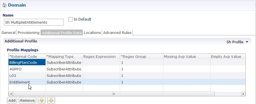
  6. Under Profile Mappings, add a new External Code and name it using the bundle profile name; in our example, the bundle profile name is Entitlement. An example configuration is shown below:

    Figure 20. External Code Configuration using Bundle Profile Name
  7. On rare occasions, you may want to select the Use Service Indications For Service Resolution option if you want the Service Indications to be put into the policy state for services resolution. Service Indications are used in the outgoing UDR/SNR to tell the HSS what data to send back to CPS.

    Note


    If you decide to select this option, do so only after consulting with Cisco Advanced Services.


LDAP/Ud Interface Configuration

For more information on LDAP/Ud interface configuration, refer to Domains.