Cisco ASR 1002-X Router Overview and Installation

This chapter describes the Cisco ASR 1002-X Router and details the procedures for installing the router on an equipment shelf, tabletop, or an equipment rack.

This chapter contains the following sections:

Cisco ASR 1002-X Router Description

The Cisco ASR 1002-X Router is a part of the Cisco ASR 1000 Aggregation Services Routers. The Cisco ASR 1002-X Router is a compact, small form factor router (SSF) that fulfil customer demands such as low power consumption and decreased usage of rack space.

The Cisco ASR 1002-X Router supports three half-height SPAs and a built-in 6xGE SPA, as also all the general-purpose routing and security features of the Cisco ASR 1000 Series Aggregation Services Routers.

The Cisco ASR 1002-X Router supports:

  • An integrated embedded services processor that provides a forwarding bandwidth of 5 Gbps, 10 Gbps, 20 Gbps, or 36 Gbps, depending on the Cisco software license that is installed on the router.

  • Hardware-based encryption with 4 Gbps of cryptography bandwidth.

  • An integrated route processor with upgradeable BootROM and 8 GB eUSB bulk storage.

  • 4 GB, 8GB, or 16 GB memory. The memory unit is field replaceable. By default, the router is shipped with the 4 GB memory unit.


Note

If you plan to use the software redundancy feature on the router, you must order either the 8 GB memory unit or the 16 GB memory unit.
  • Two USB ports for USB flash sticks.

  • 1 + 1 redundant AC or DC power supplies.

  • Stratum 3 network clocking per GR-1244-CORE, with T1/E1 BITS interface, SPAs, or any of the six built-in Gigabit Ethernet ports can be used as timing sources.

  • Console ports and auxiliary ports, Ethernet 10/100/1000 Mbps network management ports.

  • Clocking, which includes Stratum 3/G.813 Clocking, BITS, In/Out, and GPS input/output interface as well as a ToD interface. The router supports network synchronization clock prioritization.

  • Three half-height SPA slots, which can accommodate any combination of three half-height SPAs or one half-height SPA and one full-height SPA. Each SPA slot can support a throughput of up to 10 Gbps. With the exception of the 2-Port Gigabit Synchronous Ethernet SPA (SPA-2X1GE-SYNCE) and the Cisco WebEx Node SPA, all the SPAs supported by the other Cisco ASR 1000 Series Aggregation Services Routers are supported by the Cisco ASR 1002-X Router.


Note

On the Cisco ASR 1002-X Router, the copper small form-factor pluggable (SFP) port's flow control is on, regardless of the duplex setting. In contrast, on the Cisco ASR 1002 Router, the copper SFP port's flow control is off when the duplex setting is Half.
  • Built-in 6x1GE SPA providing six SPF-based Gigabit Ethernet connections, designated as SPA bay 0. For optical SFPs, the Gigabit Ethernet ports are SyncE capable. The Gigabit Ethernet ports are not SyncE capable for copper SFPs.

For information about the SFP transceiver modules that are compatible with the Cisco ASR 1002-X Built-in Gigabit Ethernet Ports (6x1GE), refer to the “Modular Optics Compatibility” section in the Cisco ASR 1000 Series Aggregation Services Routers SIP and SPA Hardware Installation Guide .

  • An optional hard drive.

The forwarding bandwidth provided by the Cisco ASR 1002-X Router's ESP can be upgraded to 36 Gbps, depending on the Cisco software license that you install. The power supply modules of the router are field-replaceable units.

This section contains the following topics:

Front View of the Cisco ASR 1002-X Router

The following image shows the front view of the Cisco ASR 1002-X Router.

Figure 1. Cisco ASR 1002-X Router—Front View

1

Built-in 6x1GE SPA in slot 0

4

SPA slot 2

2

SPA slot 1

5

ESP LEDs

3

SPA slot 3


Note

The SPAs that you insert in slots 1 to 3 are field upgradeable.

Rear View of the Cisco ASR 1002-X Router

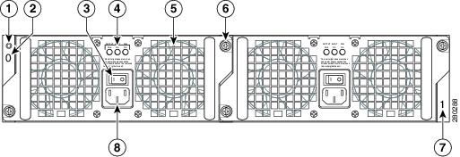
The following image shows the Cisco ASR 1002-X Router AC power supply.

Figure 2. Cisco ASR 1002-X Router AC Power Supply

1

Chassis ESD socket

5

AC power supply fan

2

AC power supply slot number 0

6

AC power supply captive installation screw

3

AC power supply On (|)/Off (O) switch

7

AC power supply slot number 1

4

AC power supply LEDs

8

AC power inlet

The following imave shows the Cisco ASR 1002-X Router DC power supply.

Figure 3. Cisco ASR 1002-X Router DC Power Supply

1

Chassis ESD socket

6

DC power supply captive installation screw

2

DC power supply slot 0 label

7

DC power supply slot 1 label

3

DC power supply switch Standby/On (|)

8

Ground lead

4

DC power supply LEDs

9

Positive lead

5

Power supply fan

10

Negative lead

Internal fans draw cooling air into the chassis and across internal components to maintain an acceptable operating temperature. The fans are located at the rear of the chassis. A two-hole grounding lug is located on the side of the chassis. Two power supplies, either two AC power supplies or two DC power supplies, can be accessed from the rear of the router.


Caution

Use only the AC power supplies or the DC power supplies in the Cisco ASR 1002-X Router. Do not mix power supply types.


Cisco ASR 1002-X Router Slot Numbering

The Cisco ASR 1002-X Router contains an integrated SIP that supports three half-height SPAs or one half-height SPA and one full-height SPA. The SPA bays are Bay 1, Bay 2, and Bay 3. The router provides a built-in 6 Gigabit Ethernet interface, and this SPA is physically located on the integrated route processor board. The built-in 6xGE SPA ports are located in the SPA Bay 0 and addressed as GE 0/0/x.

The following image shows the Cisco ASR 1002-X Router slot numbering.

Figure 4. Cisco ASR 1002-X Router Slot Numbering

1

Built-in 6x1GE SPA in slot 0

4

SPA slot 2

2

SPA slot 1

5

ESP LEDs

3

SPA slot 3

The Cisco ASR 1002-X Router has an integrated ESP which is not field upgradeable. Depending on the Cisco optional software license that is installed, the ESP forwarding bandwidth can be software field upgraded from the default bandwidth of 5 Gbps to 10 Gbps, 20 Gbps, or 36 Gbps. For more information about the software license, see the Cisco ASR 1000 Series Aggregation Services Routers Release Notes at: http://www.cisco.com/en/US/docs/routers/asr1000/release/notes/asr1k_rn_rel_notes.html

The following table describes the LEDs on the integrated ESP.

Table 1. Integrated ESP LEDs

No.

LED Label

LED

Color

Behavior in the Power-Up State

1

PWR

Power

Solid green

All the power supplies are within operational limits.

Off

Off. The router is in standby mode.

2

ACTV

Active

Green

The ESP is green when active.

3

STAT

STATUS

Green

Code has successfully downloaded, and is operational.

Yellow

Boot ROM has successfully loaded.

Red

Not booted.

4

STBY

Standby

None

Will always be off.

Power Supplies in the Cisco ASR 1002-X Router

The Cisco ASR 1002-X Router power supply module supports the following Cisco power supplies:

  • AC power supply operates between 85 V ac to 264 V ac

  • –48 V DC power supply operates between –40.5 V dc and –72 V dc

  • +24 V DC power supply operates between 21 V dc and 36 V dc

The power supplies are installed in the rear of the chassis and are hot pluggable. The Cisco ASR 1002-X Router supports up to 588 W input power from an infrastructure standpoint (cooling capacity, midplane, and power distribution), but the initial power supply development limit is up to 470 W output (AC and DC input).

AC Power Supply for the Cisco ASR 1002-X Router

The AC power supply input inlet is an International Electrotechnical Commission (IEC) connector with an AC switch. The current rating on the connector and switch is 10 A. The AC power supply is secured into the chassis with two captive screws mounted on the faceplate.

The following table describes the AC power supply LEDs on the Cisco ASR 1002-X Router.

Table 2. Cisco ASR 1002-X Router AC Power Supply LEDs

LED Label

LED

Color

Description

INPUT OK

Power supply activity

Green

The AC input voltage is greater than 85V.

None

If the LED is not illuminated, then either the input voltage is less than 70V, or the power supply is turned off.

If the AC input voltage is between 70V and 85V, the INPUT OK LED can be on, off, or flashing.

FAN OK

Power supply fan activity

A bi-color LED indicates fan status.

Green

All fans are operational.

Red

A fan failure is detected.

OUTPUT FAIL

Power supply activity

Red

If the INPUT OK LED is illuminated, this LED is red if the DC output voltages are below the minimum limit or above the maximum limit.

If the INPUT OK LED is not illuminated, this LED might be off or red.

The following image shows the AC power supply for the Cisco ASR 1002-X Router.

Figure 5. AC Power Supply for the Cisco ASR 1002-X Router

1

Chassis ESD socket

5

AC power supply fan

2

AC power supply slot number 0

6

AC power supply captive installation screw

3

AC power supply On (|) /Off (O) switch

7

AC power supply slot number 1

4

AC power supply LEDs

8

AC power supply inlet

--48 VDC Power Supply for the Cisco ASR 1002-X Router

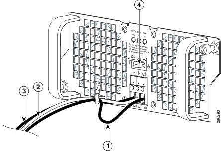
The –48 VDC power supply input connector is a Euro-style terminal block. It is compliant with safety agencies’ guidelines and electrical requirements of the supply. The DC power supply operates within specification from –40.5 VDC to –72 VDC continuously after the power supply DC input is turned on a threshold of –43.5 V is reached.

The –48 VDC power input connector accepts three wires: one positive polarity, one negative polarity, and one ground (GND) wire. There are provisions on the front panel to wire tie and strain relief the DC input wiring. The connection order is negative (–), positive (+), and GND. The DC power supply is secured into the system chassis with two captive screws mounted on the faceplate.

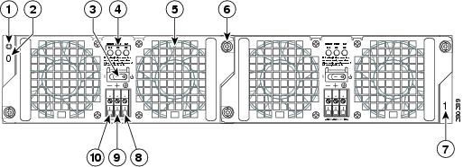
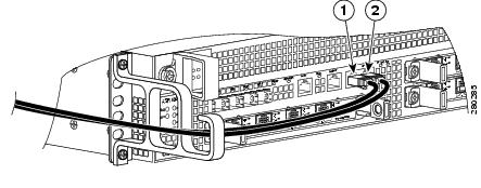
The following image shows the –48 VDC power supply for the Cisco ASR 1002-X Router.

Figure 6. –48 VDC Power Supply for the Cisco ASR 1002-X Router

1

Chassis ESD socket

6

Power supply captive installation screw

2

Power supply slot 0 label

7

Power supply slot 1 label

3

Power supply switch Standby/On (|)

8

Ground lead

4

Power supply LEDs

9

Positive lead

5

Fan

10

Negative lead

The following table lists the Cisco ASR 1002-X Router –48 VDC power supply LEDs.

Table 3. Cisco ASR 1002-X Router –48 VDC Power Supply LEDs

LED Label

LED

Color

Description

INPUT OK

A bi-color LED indicates the presence of input voltage

Green

The LED turns green to signal that the DC power supply input voltage is greater than 43.5VDC at turn-on and remains green until the level of 39 VDC is reached.

Amber

The LED turns amber if the power supply turns off due to low input voltage (falls below 39VDC) and indicates that a hazard (voltage on the terminal block) is still present. The LED remains amber and is active until around 20 V +/-5 V. If the input is below 15 V, the LED is not illuminated

FAN OK

A bi-color LED indicates power supply fan status

Green

The LED turns green when all fans are operational.

Red

The LED turns red when a fan failure is detected.

OUTPUT FAIL

Power supply activity

Red

When the LED is off, it signals that the DC output voltage is within the normal operating range. Output voltage between the minimum limit and maximum limit will not create an Output Fail alarm, but output voltages below the minimum limit or above the maximum limit will create an Output Fail alarm.

Led turns red to indicate that the DC output is out of the specified range.

When you turn on the power supply, the LED turns red for two to three seconds to test the LED operation before going off.

The output voltage alarm is raised when the output voltage is below the low end of the minimum limit or above the high end of the maximum limit. When the output voltage is above the high end of the minimum or below the low end of the maximum limit, the red state is not activated.

The following table shows the –48 VDC power supply output voltage alarm ranges.

Table 4. –48 VDC Power Supply Output Voltage Alarm Threshold Ranges

Output

Minimum

Maximum

12 V

10.0-11.2 V

12.8-13.8 V

3.3 V

2.6-3.0 V

None

+24 VDC Power Supply for the Cisco ASR 1002-X Router

This section provides information about the +24 VDC power supply at the rear of the Cisco ASR 1002-X Router. The recommended branch circuit breaker for the Cisco ASR 1002-X Router +24 VDC power supply is a 40 A UL-listed circuit breaker.

The Cisco ASR 1002-X Router has two same-type power supplies in power supply slot 0 and power supply slot 1. The power supply slot identifiers are zero (0) on the left side of the chassis, rear side, and one (1) on the right side of the chassis, rear side. The power supply switch is a Standby switch and is not considered a disconnect.

The +24 VDC power supply uses a spring-loaded terminal block. The input terminal block requires a maximum of 8 AWG multistrand wiring to support the input current. The terminal block is compliant with safety agencies’ guidelines and the electrical requirements of the supply. Use the tie wraps to dress the input cable wires; there are two tie wrap tabs on the +24 VDC power supply. The +24 VDC power supply unit is secured into the system chassis with two captive screws mounted on the faceplate.

The following image shows the +24 VDC power supply for the Cisco ASR 1002-X Router.
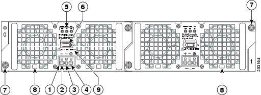
Figure 7. Cisco ASR 1002-X Router +24 VDC Power Supply

1

+24 VDC terminal block

6

Standby/On switch

2

Positive (+) lead

7

Captive fastener

3

Negative (-) lead

8

Power supply tabs

4

Ground (GND) lead

9

+27 VDC INPUT label

5

Power supply LEDs

The following table shows the definitions of the Cisco ASR 1002-X Router +24 VDC power supply LEDs.

Table 5. Cisco ASR 1002-X Router +24 VDC Power Supply LEDs

LED Label

LED

Color

Description

OUTPUT FAIL

Power supply activity

Red

When the LED is off, it signals that the +24 VDC output voltage is within the normal operating range. Output voltage between the minimum limit and maximum limit will not create an output fail alarm, but output voltages below the minimum limit or above the maximum limit will create an Output Fail alarm.

When you turn the power supply on, LED turns red for two to three seconds to test the LED operation before going off.

INPUT OK

A bicolor LED indicates the presence of input voltage

Green

The LED turns green to signal that voltage is > or = to 20 VDC at turn-on and the voltage reduces to 19.0VDC (+/- 0.5 V tolerance).

Amber

The LED turns to amber when the input voltage is active and is reduced to 16.0 VDC and indicates that a voltage on the terminal block is still present. The LED remains amber and is active until around 10 V. The LED should be OFF below 15.8 VDC.

FAN OK

A bicolor LED indicates the power supply fan status

Green

The LED turns to green when all fans are operational.

Red

The LED turns to red when a fan failure is detected.

+24 VDC Power System Input for the Cisco ASR 1002-X Router

The +24 VDC power supply operates within specification between +21 VDC and +36 VDC continuously after the power supply DC input is turned on. The power supply measures the input voltage at the power supply terminals and turns off the supply when the input voltage reaches 19.0 V +/- 0.5 V when this low voltage threshold is reached, the power supply does not resume operation until the input voltage reaches 20.0 V +/- 0.5 V. When the turn-on threshold of 20 V is reached, then the +24 VDC power supply meets all specification requirements down to the low voltage threshold of 19 V (+/- tolerance).

+24 VDC Power System Output for the Cisco ASR 1002-X Router

The +24 VDC power supply output tolerance is defined in the following table, under all combinations of +24 VDC input line variation. The total system power consumption should not exceed 470 W or output rating of each power supply.


Note

Two power supplies are used for the redundant operation. The system’s total power consumption should not exceed the rating of one power supply to maintain redundancy.
Table 6. Cisco ASR 1002-X Router +24 VDC Power System Output Voltage and Current

Output Voltage

+12 VDC

+3.3 V

Minimum

11.80 VDC

3.20 V

Nominal

12.00 VDC

3.30 V

Maximum

12.20 VDC

3.40 V

Output Current

Minimum

2.0 A

0.10 A

Maximum

39 A

3.125 A


Note

Any combination of output voltage and current cannot exceed the total power rating of 470 W.

The following are the important notes regarding the +24 VDC power supply in the Cisco ASR 1002-X Router:

  • Output Voltage Alarm Threshold—The Output Voltage Alarm is raised when the output voltage is below the low end of the minimum limit or above the high end of the maximum limit (as shown in the following table). When the output voltage is above the high end of the minimum limit or below the low end of the maximum limit, the LED does not turn to red.

Table 7. +24 VDC Output Voltage Alarm Threshold Ranges

Output

Minimum

Maximum

12 V

10.0-11.2 V

12.8-13.8 V

3.3 V

2.6 – 3.0 V

None

  • Temperature—If a fan fails, the power supply meets the functional requirements specified in above table. The calculated MTBF does not apply above 55°C with less than two fans. However, all the component stress remains within the manufacturer’s specified rating.

  • Thermal shutdown—The +24 VDC power supply shuts down to protect its components due to excessive internal temperature. The +24 VDC power supply then automatically restarts after the internal temperature returns to a safe operating level.

Power Cords Supported by the Cisco ASR 1002-X Router

The following table lists the power cords that are supported by the Cisco ASR 1002-X Router.

Table 8. Power Cords Supported by the Cisco ASR 1002-X Router

Power Cord Item Number

Description

CAB-AC-RA

Power Cord, 110 V, Right Angle

CAB-ACA-RA

Plug, Power Cord, Australia, 10 A, Right Angle

CAB-ACB10A-RA

Power Cord, Brazil, Right Angle, 10 A

CAB-ACB16A-RA

Power Cord, Brazil, Right Angle, 16 A

CAB-ACC-RA

Power Cord, China, Right Angle

CAB-ACE-RA

Power Cord, Europe, Right Angle

CAB-ACI-RA

Power Cord, Italy, Right Angle

CAB-ACR-RA

Power Cord, Argentina, Right Angle

CAB-ACS-RA

Power Cord, Switzerland, Right Angle

CAB-ACU-RA

Power Cord, UK, Right Angle

CAB-IND-RA

Power Cord, India, Right Angle

CAB-JPN-RA

Power Cord, Japan, Right Angle

Installation Methods

The Cisco ASR 1002-X Router is designed for a standalone, 2-rail 19-inch rack mount (front rail only), 4-rail 19-inch rack mount (front and rear rail).

Although rack-mounting is the preferred method of installation for the Cisco ASR 1002-X Router, you can mount the chassis on an equipment shelf or tabletop.


Note

The Cisco ASR 1002-X Router is usually shipped fully loaded. However, you can remove components such as the power supplies, from the chassis to make the chassis lighter for your rack installation.

Warning

This warning symbol means danger. You are in a situation that could cause bodily injury. Before you work on any equipment, be aware of the hazards involved with electrical circuitry and be familiar with standard practices for preventing accidents. Use the statement number provided at the end of each warning to locate its translation in the translated safety warnings that accompanied this device. Statement 1071


Warning

Before you install, operate, or service the system, read the Regulatory Compliance and Safety Information for Cisco ASR 1000 Series Aggregation Services Routers publication. This document provides important safety information you should know before working with the system. Statement 200


Note

Proceed with the installation only after you unpack your chassis and read all the site requirements for your new equipment. Proceed with the installation.

General Rack Installation Guidelines

When planning your rack installation, consider the following guidelines:

  • The Cisco ASR 1002-X Router requires a minimum of 3.5 inches (8.9 cm) rack units of vertical rack space. Measure the proposed rack location before mounting the chassis in the rack.

  • Before using a particular rack, check for obstructions (such as a power strip) that could impair rack mount installation. If a power strip does impair a rack mount installation, remove the power strip before installing the chassis, and replace the strip after the chassis is installed

    .
  • Allow sufficient clearance around the rack for maintenance. If the rack is mobile, you can push it back near a wall or cabinet for normal operation and pull it out for maintenance (installing or moving cards, connecting cables, or replacing or upgrading components). Otherwise, allow 19 inches (48.3 cm) of clearance space to remove field-replaceable units.

  • Maintain a minimum clearance of 3 inches on the front side and back side of the chassis for the cooling air inlet and exhaust ports, respectively. Avoid placing the chassis in an overly congested rack or next to another equipment rack; otherwise, the heated exhaust air from other equipment may enter the inlet air vents and cause an overtemperature condition inside the router.


Caution

To prevent the chassis from overheating, never install a Cisco ASR 1002-X Router in an enclosed room that is not properly ventilated or air conditioned.


  • Always install the heavier equipment in the lower half of a rack to maintain a low center of gravity to prevent the rack from falling over.
  • Install and use the cable management brackets included with the Cisco ASR 1002-X Router to keep the cables organized and out of the way of the cards and processors. Ensure that cables from other equipment already installed in the rack do not impair access to the cards or require you to disconnect cables unnecessarily to perform equipment maintenance or upgrades.

  • Install rack stabilizers (if available) before you mount the chassis.

  • Provide an adequate chassis ground (earth) connection for your router chassis.

In addition to the preceding guidelines, review the precautions for avoiding excessive temperature conditions described in the “Site Environmental Requirements” section on page 5-9 .

The following table provides the Cisco ASR 1002-X Router dimensions and weight information.

Table 9. Cisco ASR 1002-X Router Dimensions and Weight

Attribute

Dimensions

Depth

22.50 in. (57.15 cm)(includes card handles, cable management brackets, power supply handles).

Height

3.47 in. (8.813 cm)—2RU rack mount per EIA RS-310

Width

17.25 in. (43.815 cm)—19 inch (48.26 cm) rack mount

Weight

43.35 lbs (19.662 kg)—fully configured

Guidelines for an Equipment Shelf or Tabletop Installation

The chassis should already be in the area where you will install it. If you have not determined where to install your chassis, see the “Cisco ASR 1000 Series Routers Component Overview” section on page 2-1 for information about site considerations.

If you are not rack-mounting your Cisco ASR 1000 series chassis, place it on a sturdy equipment shelf or tabletop.

When installing the Cisco ASR 1002-X Router on an equipment shelf or tabletop, ensure that the surface is clean and that you have considered the following:

  • The Cisco ASR 1002-X Router requires at least 3 inches (7.62 cm) of clearance at the inlet and exhaust vents (the front, top, and rear sides of the chassis).

  • The Cisco ASR 1002-X Router should be installed off the floor. Dust that accumulates on the floor is drawn into the interior of the router by the cooling fans. Excessive dust inside the router can cause overtemperature conditions and component failures.

  • There must be approximately 19 inches (48.3 cm) of clearance at the front and rear of the chassis to install and replace FRUs, or to access network cables and equipment.

  • The Cisco ASR 1002-X Router needs adequate ventilation. Do not install it in an enclosed cabinet where ventilation is inadequate.

  • Ensure that the cable management bracket is available if you plan to install it on the front of the chassis.

  • An adequate chassis ground (earth) connection exists for your router chassis. (See the Attaching a Chassis Ground Connection

  • When handling the chassis, always follow proper lifting practices as outlined in the “Electrical Safety” section on page 5-21 .

Equipment Shelf or Tabletop Installation Procedure

To mount your Cisco ASR 1002-X Router on an equipment shelf or tabletop, follow these steps.

SUMMARY STEPS

  1. Remove debris and dust, if any, from the tabletop or platform, as well as from the surrounding area.
  2. Lift the chassis into position on the equipment shelf or tabletop (see following figure).
  3. Attach the front rack mount brackets. Locate the threaded holes in the front sides of the chassis (first holes beyond the vent holes).
  4. Align the front rack mount bracket to one side of the chassis.
  5. Insert and tighten the black screws that shipped with the chassis on one side.
  6. Repeat Step-2 through Step-3 on the other side of the chassis. Use all the screws to secure the rack mount brackets to the chassis.
  7. Gather the two cable management brackets and screws shipped with your chassis. Attaching the Cable Management Bracket shows the cable management brackets attached on the front of the Cisco ASR 1002-X Router.
  8. Screw the cable management bracket to each side of the rack mount brackets already attached to the chassis. Use two screws for each cable management bracket. Use the packet of four screws.
  9. Verify if all the screws are securely tightened.
  10. Go to the Attaching a Chassis Ground Connection to continue the installation.

DETAILED STEPS


Step 1

Remove debris and dust, if any, from the tabletop or platform, as well as from the surrounding area.

Step 2

Lift the chassis into position on the equipment shelf or tabletop (see following figure).

At least two people are required to lift the chassis onto a tabletop or platform. To prevent injury, keep your back straight and lift with your legs, not your back. Statement 164

Figure 8. Lifting the Chassis
The chassis in the image does not represent the Cisco ASR 1002-X Router.
Step 3

Attach the front rack mount brackets. Locate the threaded holes in the front sides of the chassis (first holes beyond the vent holes).

Step 4

Align the front rack mount bracket to one side of the chassis.

Step 5

Insert and tighten the black screws that shipped with the chassis on one side.

Step 6

Repeat Step-2 through Step-3 on the other side of the chassis. Use all the screws to secure the rack mount brackets to the chassis.

Note 
The chassis rack mount brackets must be installed first so that you can attach the cable management brackets to the chassis rack mount brackets after the chassis is installed in the rack.
Step 7

Gather the two cable management brackets and screws shipped with your chassis. Attaching the Cable Management Bracket shows the cable management brackets attached on the front of the Cisco ASR 1002-X Router.

Note 
Ensure that the cable management U feature device has the open end pointing upwards when you attach it to the chassis
Figure 9. Attaching the Cable Management Brackets to the Cisco ASR 1002-X Router

1

Cable management bracket top and bottom screw

3

Chassis front rack mount bracket

2

Cable management bracket

Step 8

Screw the cable management bracket to each side of the rack mount brackets already attached to the chassis. Use two screws for each cable management bracket. Use the packet of four screws.

Step 9

Verify if all the screws are securely tightened.

Step 10

Go to the Attaching a Chassis Ground Connection to continue the installation.


Rack-Mounting the Cisco ASR 1002-X Router

The Cisco ASR 1002-X Router can be installed in an existing rack with equipment or in an empty rack with no equipment. The chassis can be mounted on either of these rack types:

  • Two-post rack, either 19-inch or 23-inch equipment rack. Inner clearance (the width between the inner sides of the two posts or rails) must be at least 19 inches (48.26 cm). The height of the chassis is 3.47 inches (8.8 cm). Air flow through the chassis is from front to back.

  • Four-post, 19-inch equipment rack. Inner clearance (the width between the inner sides of the two posts or rails) must be at least 19 inches (48.26 cm). The height of the chassis is 3.47 inches (8.8 cm). Air flow through the chassis is from front to back.


Note

When handling the chassis, always follow proper lifting practices. See the “Chassis-Lifting Guidelines” section on page 5-23 .

The Cisco ASR 1002-X Router can be installed with both front or rear rack mount brackets.

Verifying Rack Dimensions

Before you install the chassis, measure the space between the vertical mounting flanges (rails) on your equipment rack to verify that the rack conforms to the measurements shown in the following image.

SUMMARY STEPS

  1. Mark and measure the distance between the holes on the left and right mounting rails.
  2. Measure the space between the inner edges of the left front and right front mounting flanges on the equipment rack.

DETAILED STEPS


Step 1

Mark and measure the distance between the holes on the left and right mounting rails.

The distance should measure 18.31 inches ± 0.06 inches (46.5 cm ± 0.15 cm).

Note 
Measure for pairs of holes near the bottom, middle, and top of the equipment rack to ensure that the rack posts are parallel.
Step 2

Measure the space between the inner edges of the left front and right front mounting flanges on the equipment rack.

The space must be at least 17.7 inches (45 cm) to accommodate the chassis that is 17.25 inches (43.8 cm) wide and fits between the mounting posts on the rack.

Figure 10. Verifying the Equipment Rack Dimensions

Attaching the Chassis Rack Mount Brackets

This section explains how to attach the front and rear rack mount brackets to the chassis. Before installing the chassis in the rack, you must install the rack mount brackets on each side of the chassis.

The parts and tools required for installing the rack mount brackets and cable management brackets are listed in the “Tools and Equipment” section on page 5-23 .


Note

The cable management brackets are attached to the chassis after you install the chassis rack mount brackets on the chassis and mount the chassis in the rack.

Chassis Front Rack Mount Brackets

Determine where you want the chassis to be mounted in the rack. If you are mounting more than one chassis in the rack, start from the bottom up or the center of the rack. Attaching the Front Rack Mount Brackets to the Cisco ASR 1002-X Router shows the brackets attached to the chassis. Depending on the bracket holes you use, the chassis may protrude in the rack.

To install the front rack mount brackets on the Cisco ASR 1002-X Router, perform the following steps:

SUMMARY STEPS

  1. Locate the threaded holes on the side of the chassis. Ensure that you hold the front rack mount bracket with the ear and holes facing outward and towards the front of the chassis.
  2. Position the front rack mount bracket’s top hole with the chassis, first top hole behind the side vent holes.
  3. Insert and tighten the black screws shipped with the router on one side.
  4. Repeat Step 1 through Step 3 on the other side of the chassis. Use the black screws to secure the rack mount brackets to the chassis.
  5. Install the chassis in a rack. To install the Cisco ASR 1002-X Router in a rack, see the information provided in the Installing the Cisco ASR 1002-X Router in a Rack.

DETAILED STEPS


Step 1

Locate the threaded holes on the side of the chassis. Ensure that you hold the front rack mount bracket with the ear and holes facing outward and towards the front of the chassis.

The following image shows where to attach the front rack mount brackets to the Cisco ASR 1002-X Router.

Figure 11. Attaching the Front Rack Mount Brackets to the Cisco ASR 1002-X Router

1

Front rack mount bracket ear and holes

3

Front rack mount bracket screws

2

Front rack mount bracket

Step 2

Position the front rack mount bracket’s top hole with the chassis, first top hole behind the side vent holes.

Step 3

Insert and tighten the black screws shipped with the router on one side.

Step 4

Repeat Step 1 through Step 3 on the other side of the chassis. Use the black screws to secure the rack mount brackets to the chassis.

Step 5

Install the chassis in a rack. To install the Cisco ASR 1002-X Router in a rack, see the information provided in the Installing the Cisco ASR 1002-X Router in a Rack.


What to do next

This completes the steps for attaching the front rack mount brackets to the Cisco ASR 1002-X Router.

Chassis Rear Rack Mount Brackets

If you are rack mounting the chassis using the rear rack mount brackets, the chassis gets recessed in the rack.

To install the rear rack mount brackets on the Cisco ASR 1002-X Router, perform the following steps:

SUMMARY STEPS

  1. Locate the threaded holes on the rear side of the chassis. Ensure that you hold the rear rack mount bracket with the ear and holes facing outward and towards the rear of the chassis.
  2. Position the rear rack mount bracket top hole with the chassis top hole from the back.
  3. Insert and tighten the screws on one side.
  4. Repeat Step 1 through Step 3 on the other side of the chassis. Use the remaining screws to secure the rear rack mount brackets to the chassis.

DETAILED STEPS


Step 1

Locate the threaded holes on the rear side of the chassis. Ensure that you hold the rear rack mount bracket with the ear and holes facing outward and towards the rear of the chassis.

The following image shows where to attach the rear rack mount brackets to the Cisco ASR 1002-X Router.

Figure 12. Attaching the Rear Rack Mount Brackets to the Cisco ASR 1002-X Router

1

Rear rack mount bracket ear and holes

3

Rear rack mount bracket screws

2

Rear rack mount bracket

Step 2

Position the rear rack mount bracket top hole with the chassis top hole from the back.

Step 3

Insert and tighten the screws on one side.

Step 4

Repeat Step 1 through Step 3 on the other side of the chassis. Use the remaining screws to secure the rear rack mount brackets to the chassis.


What to do next

This completes the steps for attaching the rear rack mount brackets to the Cisco ASR 1002-X Router.


Caution

To make the installation easier, before you mount the Cisco ASR 1002-X Router in a rack, use the information provided in this chapter to determine which rack mount bracket ear holes to use when positioning the chassis in the rack. Using the designated ear holes on the rack mount bracket simplifies installation of the cable management bracket.


Installing the Cisco ASR 1002-X Router in a Rack

After installing the rack mount brackets on the chassis, you mount the chassis by securing the rack mount brackets to the two posts or the mounting strips in the rack using the screws provided. Because the rack mount brackets support the weight of the entire chassis, use all the screws to fasten the two rack mount brackets to the rack posts.


Warning

To prevent bodily injury when mounting or servicing this unit in a rack, you must take special precautions to ensure that the system remains stable. The following guidelines are provided to ensure your safety:-This unit should be mounted at the bottom of the rack if it is the only unit in the rack.-When mounting this unit in a partially filled rack, load the rack from the bottom to the top with the heaviest component at the bottom of the rack.-If the rack is provided with stabilizing devices, install the stabilizers before mounting or servicing the unit in the rack. Statement 1006


We recommend that you allow at least 1 or 2 inches (2.54 or 5.08 cm) of vertical clearance between the router and any equipment directly above and below it.

To install the chassis in the rack, perform the following steps:

SUMMARY STEPS

  1. On the chassis, ensure that all the screw fasteners on the installed components are securely tightened.
  2. Ensue that your path to the rack is unobstructed. If the rack is on wheels, ensure that the brakes are engaged or that the rack is otherwise stabilized. (See the next sections on the types of racks you can use to install the chassis.)
  3. (Optional) Install a shelf in the rack to support the Cisco ASR 1002-X Router. This helps support the chassis when you secure it to the rack.
  4. Lift the chassis into position between the rack posts with the help of another person.
  5. Align the mounting bracket holes with the rack post holes and attach the chassis to the rack.
  6. Position the chassis until the rack-mounting flanges are flush against the mounting rails on the rack.
  7. Hold the chassis in position against the mounting rails in the equipment rack and perform these steps:
  8. Tighten all the screws on each side to secure the chassis to the equipment rack.

DETAILED STEPS


Step 1

On the chassis, ensure that all the screw fasteners on the installed components are securely tightened.

Step 2

Ensue that your path to the rack is unobstructed. If the rack is on wheels, ensure that the brakes are engaged or that the rack is otherwise stabilized. (See the next sections on the types of racks you can use to install the chassis.)

Step 3

(Optional) Install a shelf in the rack to support the Cisco ASR 1002-X Router. This helps support the chassis when you secure it to the rack.

Step 4

Lift the chassis into position between the rack posts with the help of another person.

Step 5

Align the mounting bracket holes with the rack post holes and attach the chassis to the rack.

Note 
If you are using a shelf, raise the chassis to the level of the shelf. Let the bottom of the chassis rest on the brackets, but continue to support the chassis.
Step 6

Position the chassis until the rack-mounting flanges are flush against the mounting rails on the rack.

Tip 

To allow space to attach the cable management brackets to the chassis in the rack easily, ensure that you use the rack mount bracket ear holes mentioned in the subsequent steps.

Step 7

Hold the chassis in position against the mounting rails in the equipment rack and perform these steps:

  1. Insert the bottom screw into the second hole from the bottom of the rack mount ear and use a hand-held screw driver to tighten the screw to the rack rail.

    Tip 

    To make installation easier, insert one screw at the bottom of the chassis and the next screw at the top of the chassis diagonally from the first screw.

  2. Insert the top screw into the second hole from the top of the rack mount ear diagonally from the bottom screw, and tighten the screw to the rack rail.

  3. Insert the four screws to secure the chassis to the rack equipment.

    Tip 

    As a result of using the specified rack mount bracket ear holes, the cable management bracket can be easily attached to the rack mount bracket when the chassis is in the rack.

Step 8

Tighten all the screws on each side to secure the chassis to the equipment rack.


Two-Post Rack Installation

The Cisco ASR 1002-X Router can be installed on a two-post 19-inch or 23-inch rack.


Note

Inner clearance (the width between the inner sides of the two posts or rails) must be at least 19 inches (48.26 cm). The height of the chassis is 3.47 inches (8.8 cm). Air flow through the chassis is from front to back.

Caution

If you are using a two-post rack, secure the rack to the floor surface to prevent tipping and avoid bodily injury and component damage.


Perform the following procedure to install a two-post rack:

SUMMARY STEPS

  1. Position the chassis such that the front is closest to you and lift it carefully into the rack.
  2. Slide the chassis into the rack, pushing it back until the brackets meet the mounting strips or posts on both sides of the rack.
  3. Keeping the brackets flush against the posts or mounting strips, align the holes in the brackets with the holes on the rack or mounting strips.
  4. For each bracket, insert and tighten two screws to the rack on both sides.

DETAILED STEPS


Step 1

Position the chassis such that the front is closest to you and lift it carefully into the rack.

Caution 

To prevent injury, avoid any sudden twists or moves.

The following image shows where to attach the rack mount brackets to the Cisco ASR 1002-X Router.

Figure 13. Attaching the Rack Mount Brackets to the Cisco ASR 1002-X Router

1

Rack equipment rail

2

Rack mount bracket ear and holes

Step 2

Slide the chassis into the rack, pushing it back until the brackets meet the mounting strips or posts on both sides of the rack.

Step 3

Keeping the brackets flush against the posts or mounting strips, align the holes in the brackets with the holes on the rack or mounting strips.

Step 4

For each bracket, insert and tighten two screws to the rack on both sides.

This completes the procedure for installing the chassis on a two-post rack. Proceed to the Attaching a Grounding Lug to the Chassis Ground Connector for information about how to continue with the installation.


Four-Post Rack Installation

The Cisco ASR 1002-X Router can be flush-mounted in a 19-inch equipment rack using the rack-mounting kit provided with your system. The Cisco ASR 1002-X Router can be mounted into the rack using two recommended methods:

  • Installing the chassis in an existing rack with equipment.

  • Installing an empty chassis in a rack with no equipment installed.

When handling the chassis, always follow proper lifting practices. See the “Chassis-Lifting Guidelines” section on page 5-23 .


Note

Inner clearance (the width between the inner sides of the two posts or rails) must be at least 19 inches (48.26 cm). The height of the chassis is 3.47 inches (8.8 cm). Airflow through the chassis is from front to back.

Note

Ensure that the rack is stabilized.

SUMMARY STEPS

  1. (Optional) Install a shelf in the rack to support the Cisco ASR 1002-X Router. If you are using a shelf, raise the chassis to the level of the shelf. Let the bottom of the chassis rest on the brackets, but continue to support the chassis. Lift the chassis into the rack using the side handles and grasping underneath the power supply bays, with the help of another person.
  2. Position the chassis until the rack-mounting flanges are flush against the mounting rails on the rack.
  3. Hold the chassis in position against the mounting rails while the second person finger-tightens a screw to the rack rails on each side of the chassis.
  4. Tighten all the screws on each side to secure the chassis to the equipment rack (see the following image).
  5. Use a level to verify that the tops of the two brackets are level, or use a measuring tape to verify that both the brackets are the same distance from the top of the rack rails.

DETAILED STEPS


Step 1

(Optional) Install a shelf in the rack to support the Cisco ASR 1002-X Router. If you are using a shelf, raise the chassis to the level of the shelf. Let the bottom of the chassis rest on the brackets, but continue to support the chassis. Lift the chassis into the rack using the side handles and grasping underneath the power supply bays, with the help of another person.

Step 2

Position the chassis until the rack-mounting flanges are flush against the mounting rails on the rack.

Note 
Use the second hole up from the bottom of the rack mount bracket and the second hole down from the top of the rack mount bracket. This makes it easier to attach the cable management bracket to the chassis in the equipment rack.
Step 3

Hold the chassis in position against the mounting rails while the second person finger-tightens a screw to the rack rails on each side of the chassis.

Step 4

Tighten all the screws on each side to secure the chassis to the equipment rack (see the following image).

Figure 14. Cisco ASR 1002-X Router on a Four-Post Rack—Front and Rear Rack-Mounting

1

Rear rack equipment rail

3

Front rack mount bracket ear and holes

2

Rear rack mount bracket ear and holes

4

Front rack equipment rail

Step 5

Use a level to verify that the tops of the two brackets are level, or use a measuring tape to verify that both the brackets are the same distance from the top of the rack rails.


What to do next

This completes the procedure for installing the chassis in the rack. Proceed to the Attaching the Cable Management Bracket for information about how to continue with the installation.

Attaching the Cable Management Bracket

The cable management brackets are mounted to each rack mount bracket on the chassis to provide cable management to both sides of the chassis (parallel with card orientation). These brackets are screw-mounted to the rack mount brackets to allow easy installation and removal of cables.

The cable management brackets for the Cisco ASR 1002-X Router contain an independent cable management U type feature with four screws and provides cable dressing for each card module slot.


Note

Ensure that the cable management bracket U type feature is facing upwards when you attach it to the chassis.

Follow these steps to attach the cable management brackets to both sides of the Cisco ASR 1002-X Router in the rack:

SUMMARY STEPS

  1. Align the cable management bracket to the rack mount bracket on one side of the Cisco ASR 1002-X Router. The cable management bracket aligns to the top hole of the chassis rack mount bracket.
  2. Using a Phillips screwdriver, insert the screw through cable management bracket and into the chassis rack mount and tighten the screw. Use the package of four screws shipped with the router.
  3. Using the bottom rack mount ear hole, insert the screw through cable management bracket and into the chassis rack mount (see Chassis Rack Mount Bracket Ear Holes for the Cable Management Brackets).

DETAILED STEPS


Step 1

Align the cable management bracket to the rack mount bracket on one side of the Cisco ASR 1002-X Router. The cable management bracket aligns to the top hole of the chassis rack mount bracket.

Step 2

Using a Phillips screwdriver, insert the screw through cable management bracket and into the chassis rack mount and tighten the screw. Use the package of four screws shipped with the router.

The following imave shows the locations at which to attach the front rack mount brackets to the Cisco ASR 1002-X Router in a rack.

Figure 15. Chassis Rack Mount Bracket Ear Holes for the Cable Management Brackets

1

Secure the cable management top screw and bottom to this ear hole

3

Front rack mount bracket

2

Cable-management bracket

Step 3

Using the bottom rack mount ear hole, insert the screw through cable management bracket and into the chassis rack mount (see Chassis Rack Mount Bracket Ear Holes for the Cable Management Brackets).


What to do next

This completes the procedure for installing the cable management brackets on the chassis.

Attaching a Chassis Ground Connection

Connecting the Cisco ASR 1002-X chassis to ground is required for all DC-powered installations and AC-powered installation where compliance with Telcordia grounding requirements is necessary.


Caution

The dual-lug chassis ground stud must be installed and all the cards and filler plates must be fully inserted, screwed in, and earthed to prevent a potential hazard in a telecom line.


Have the recommended tools and supplies available before you begin this procedure.


Warning

This equipment must be grounded. Never defeat the ground conductor or operate the equipment in the absence of a suitably installed ground conductor. Contact the appropriate electrical inspection authority or an electrician if you are uncertain that suitable grounding is available. Statement 1024


Before you connect power or turn on power to your chassis, you must provide an adequate chassis ground (earth) connection for the chassis. The chassis ground lug (two) and the respective screws (four) are provided in the accessory kit that shipped with your Cisco ASR 1002-X Router.


Caution

The grounding wire is always the first to be installed or connected and the last to be removed or disconnected.


The following tools, equipment, and supplies are necessary to connect the system ground to the chassis:

  • P

    hillips screwdriver

  • Dual-lug chassis ground component (two) and respective screws (four) (shipped with the accessory kit)

  • Grounding wire

The following image shows the location of the ground lug on the side of Cisco ASR 1002-X Router.

Figure 16. Cisco ASR 1002-X Router Chassis Ground Lug Location

1

Cisco ASR 1002-X Router ground stud location.

To attach the grounding lug to the chassis ground connector on your chassis, follow these steps:

SUMMARY STEPS

  1. Use the wire stripper to strip one end of the AWG #6 wire approximately 0.75 inches (1.905 cm).
  2. Insert the AWG #6 wire into the wire receptacle in the grounding lug. Use the manufacturer's recommended crimping tool to carefully crimp the wire receptacle around the wire. This step is required to ensure proper mechanical connection.
  3. Attach the grounding lug to the wire on the left to avoid having the grounding wire overlapping the power supply.
  4. Locate the chassis ground connector on the side of your chassis.
  5. The following image shows how to attach the grounding lug to the chassis ground connector.
  6. Insert the two screws through the holes in the grounding lug.
  7. Use the Number 2 Phillips screwdriver to carefully tighten the screws until the grounding lug is held firmly to the chassis. Do not overtighten the screws.
  8. Connect the opposite end of the grounding wire to the appropriate grounding point at your site to ensure an adequate chassis ground.

DETAILED STEPS


Step 1

Use the wire stripper to strip one end of the AWG #6 wire approximately 0.75 inches (1.905 cm).

Step 2

Insert the AWG #6 wire into the wire receptacle in the grounding lug. Use the manufacturer's recommended crimping tool to carefully crimp the wire receptacle around the wire. This step is required to ensure proper mechanical connection.

The following image shows the parts of the grounding lug.

Figure 17. Parts of the Grounding Lug

1

Chassis ground connector holes

3

Ground lug screws

2

Grounding lug

4

Ground wire

Step 3

Attach the grounding lug to the wire on the left to avoid having the grounding wire overlapping the power supply.

Step 4

Locate the chassis ground connector on the side of your chassis.

Step 5

The following image shows how to attach the grounding lug to the chassis ground connector.

Figure 18. Attaching a Grounding Lug to the Chassis Ground Connector

1

Chassis ground connector

2

Ground symbol

Step 6

Insert the two screws through the holes in the grounding lug.

Step 7

Use the Number 2 Phillips screwdriver to carefully tighten the screws until the grounding lug is held firmly to the chassis. Do not overtighten the screws.

Step 8

Connect the opposite end of the grounding wire to the appropriate grounding point at your site to ensure an adequate chassis ground.


What to do next

This completes the procedure for attaching a chassis ground connection. Go to the following cabling sections for information on attaching cables.

Connecting the Console and Auxiliary Port Cables

This section describes how to attach a cable to the console ports or auxiliary ports on the Cisco ASR 1002-X Router. This router uses RJ-45 ports for both the auxiliary port and the console port. On the front panel of the router, the integrated route processor console port and auxiliary port are labeled CON and AUX, respectively.


Caution

To meet Class A emission requirements, shielded cables must be used for the console and auxiliary port connectors.


Before using the console interface on the router via a terminal or PC, you must perform the following steps:

SUMMARY STEPS

  1. Before connecting a terminal to the console port, configure the terminal to match the chassis console port as follows: 9600 baud, 8 data bits, no parity, 1 stop bits (9600 8N1).
  2. Connect to the port using the RJ-45 to DB-9 cable.
  3. After you establish normal router operation, disconnect the terminal, if required.

DETAILED STEPS


Step 1

Before connecting a terminal to the console port, configure the terminal to match the chassis console port as follows: 9600 baud, 8 data bits, no parity, 1 stop bits (9600 8N1).

Step 2

Connect to the port using the RJ-45 to DB-9 cable.

Note 
For information about how to change the default settings to meet the requirements of your terminal or host, see the Cisco IOS Terminal Services Configuration Guide .
Step 3

After you establish normal router operation, disconnect the terminal, if required.


Management Ethernet Port Cable Connection


Caution

To comply with Class A emission requirements, a shielded Ethernet cable must be used for the connection.


On the front panel of the router, the Management Ethernet port is labeled MGMT ETHERNET. To use the Management Ethernet interface on the router, perform the following steps:

SUMMARY STEPS

  1. Insert an Ethernet RJ-45 cable into the MGMT ETHERNET port.
  2. Insert the other end of the RJ-45 cable to your management device or network.

DETAILED STEPS


Step 1

Insert an Ethernet RJ-45 cable into the MGMT ETHERNET port.

Step 2

Insert the other end of the RJ-45 cable to your management device or network.


What to do next


Note

A connection will not be established when setting up an out-of-band connection or modem connection in the auxiliary port and the console port.

Cisco ASR 1002-X Router Power Supplies

This section describes the Cisco ASR 1002-X Router power supplies and how to connect them:

Read the safety warnings before you begin.


Warning

The covers are an integral part of the safety design of the product. Do not operate the unit without the covers installed. Statement 1077


Warning

When you install the unit, the ground connection must always be made first and disconnected last. Statement 1046


Warning

Before performing any of the following procedures, ensure that power is removed from the DC circuit. Statement 1003


Warning

Only trained and qualified personnel should be allowed to install, replace, or service this equipment. Statement 1030


Warning

Never install an AC power module and a DC power module in the same chassis. Statement 1050


Warning

Installation of the equipment must comply with local and national electrical codes. Statement 1074


Warning

When installing or replacing the unit, the ground connection must always be made first and disconnected last. Statement 1046


Warning

This equipment must be grounded. Never defeat the ground conductor or operate the equipment in the absence of a suitably installed ground conductor. Contact the appropriate electrical inspection authority or an electrician if you are uncertain that suitable grounding is available. Statement 1024


Warning

This unit has two power supply connections. All connections must be removed to de-energize the unit. Statement 1028


Warning

This product relies on the building’s installation for short-circuit (overcurrent) protection. Ensure that the protective device is rated not greater than: AC power supplies 20 A and DC power supplies 30 A. Statement 1005


Connecting AC Input Power to Cisco ASR 1002-X Router

This section provides the procedures for connecting AC-input, –48 VDC input power, and the +24 VDC input power to your Cisco ASR 1002-X Router.

For detailed instructions for removing and replacing the Cisco ASR 1002-X Router AC and DC power supplies, see Chapter 14, “Removing and Replacing FRUs from the Cisco ASR 1000 Series Routers.”

To connect AC power to the Cisco ASR 1002-X Router, follow these steps:

SUMMARY STEPS

  1. At the rear of the router, ensure that the power switch is in the Off (O) position.
  2. Insert the AC power cable into the power supply AC inlet.
  3. To ensure that the AC power cord does not interfere with other cables or wires, dress the AC power cable in one of the following ways.
  4. Plug the AC power supply cable into the AC power source.

DETAILED STEPS


Step 1

At the rear of the router, ensure that the power switch is in the Off (O) position.

Note 
Turn the power switch to the On (|) position after both sides of the power cord are connected.

1

Chassis ESD socket

5

AC power supply fan

2

AC power supply slot number 0

6

AC power supply captive installation screw

3

AC power supply On (|) /Off (O) switch

7

AC power supply slot number 1

4

AC power supply LEDs

8

AC power inlet

Step 2

Insert the AC power cable into the power supply AC inlet.

Step 3

To ensure that the AC power cord does not interfere with other cables or wires, dress the AC power cable in one of the following ways.

  • Leave a small service loop in the AC power cord from the inlet and then secure the power cord through the AC power supply handle.

1

AC power cord

  • Take the power cord and run it below the handles of the right and left power supplies. Make sure the power cord is hanging loose so that it does not get disconnected from the AC power inlet.
Caution 

Do not run the AC power cord through the power supply handles .

Note 
Using a tie wrap for the AC power cable is optional. However, if you do attach the AC power cable to a power supply tab and then you remove the AC power cable for some reason, check for any damage to the cable after you cut the tie wrap. If the power cord is damaged, replace it immediately.
Step 4

Plug the AC power supply cable into the AC power source.


What to do next

This completes the procedure for connecting an AC power supply in the Cisco ASR 1002-X Router.

Connecting the –48 VDC Input Power to the Cisco ASR 1002-X Router

The –48 VDC power supply input connector is a Euro-style terminal block. A means to provide strain relief to the input wires is provided on the power supply. The connection order is negative (–), positive (+), and GND. However, this is the order from left to right in which the terminals appear on the power supply, not the order in which the leads should be connected during installation. The order in which the leads should be attached is GND, positive (+), and negative (-).

The recommended branch circuit breaker for the Cisco ASR 1002-X Router –48 VDC power supply is 30 A. Use an AWG #10 wire gauge on the 30 A circuit.

The following figure shows the –48 VDC power supply for the Cisco ASR 1002-X Router.

Figure 19. –48 VDC Power Supply for the Cisco ASR 1002-X Router

1

Chassis ESD socket

6

–48 VDC power supply captive installation screw

2

–48 VDC power supply slot 0 label

7

–48 VDC power supply slot 1 label

3

–48 VDC power supply switch Standby/On

8

Ground lead

4

–48 VDC power supply LEDs

9

Positive lead

5

Fan

10

Negative lead

The following table describes the LEDs on the Cisco ASR 1002-X Router –48 VDC power supply.

Table 10. Cisco ASR 1002-X Router –48 VDC Power Supply LEDs

LED Label

LED

Color

Description

INPUT OK

A bi-color LED indicates the presence of input voltage

Green

LED turns green to signal that the –48 VDC power supply input voltage is greater than 43.5VDC at start and remains green down to 39VDC.

Amber

The LED turns amber if the power supply turns off due to low input voltage (falls below 39VDC) and indicates that there is still a hazard present (voltage on the terminal block). The LED remains amber and is active till around 20 V +/-5 V. The LED is not illuminated if the input is below 15 V.

FAN OK

A bi-color LED indicates power supply fan status

Green

The LED turns s green when all the fans are operational.

Red

The LED turns red when a fan failure is detected.

OUTPUT FAIL

Power supply activity

Red

When the LED is off, it signals that the –48 VDC output voltage is within the normal operating range. Output voltage between the minimum and maximum limits will not create an output fail alarm, and output voltages below the minimum or above the maximum will create an output fail alarm.

The Led turns red to indicate that the –48 VDC output is out of the specified range.

When you turn the power supply on, the LED turns red for 2 to 3 seconds to test the LED operation before going off.


Note

The color coding of the –48 VDC input power supply leads depends on the color coding of the –48 VDC power source at your site. Typically, green or green/yellow is used for ground. Ensure the lead color coding you choose for the –48 VDC input power supply matches the LED color coding used at the –48 VDC power source.

DANGER

When you install the unit, the ground connection must always be made first and disconnected last. Statement 1046


This section describes how to connect the –48 VDC power supply in the Cisco ASR 1002-X Router:

SUMMARY STEPS

  1. At the rear of the router, check that the power supply Standby switch is in the Standby (see Cisco ASR 1002-X Router –48 VDC Power Supply Terminal Block Cable Connections ) position.
  2. Ensure that the negative and positive leads are disconnected from the site power source.
  3. Using a wire stripper, strip approximately 0.55 inch (1.39 cm) from the negative, positive, and ground lead.
  4. Insert the stripped end of the ground lead all the way into the ground lead receptacle on the –48 VDC input power supply, and tighten the receptacle screw using a 3.5 mm flat-blade screwdriver to a torque of 0.5 to 0.6 Nm.
  5. Insert the stripped end of the positive lead all the way into the positive lead receptacle and tighten the receptacle screw using the same 3.5mm flat-blade screwdriver.
  6. Repeat this step for the negative lead.
  7. After tightening the receptacle screw for the ground, positive, and negative –48 VDC-input leads, use a cable tie to secure the three leads to the power supply faceplate, as shown in Cisco ASR 1002-X Router –48 VDC Power Supply Terminal Block Cable Connections. When securing the ground, positive, and negative –48 VDC-input leads to the power supply faceplate, leave a small service loop in the ground lead to ensure that the ground lead is the last lead to disconnect from the power supply if a great deal of strain is placed on all three leads, as shown in Cisco ASR 1002-X Router –48 VDC Power Supply Terminal Block Cable Connections.
  8. Connect the ground, positive, and negative leads to the power source.
  9. Turn the branch source breaker on.
  10. Place the –48 VDC Standby switch in the On (|) position. The power supply LEDs light when power is supplied to the router.

DETAILED STEPS


Step 1

At the rear of the router, check that the power supply Standby switch is in the Standby (see Cisco ASR 1002-X Router –48 VDC Power Supply Terminal Block Cable Connections ) position.

Figure 20. Cisco ASR 1002-X Router –48 VDC Power Supply Terminal Block Cable Connections

1

Ground lead with service loop and tie wrap

3

Negative lead

2

Positive lead

4

–48 VDC power supply Standby switch

Step 2

Ensure that the negative and positive leads are disconnected from the site power source.

Step 3

Using a wire stripper, strip approximately 0.55 inch (1.39 cm) from the negative, positive, and ground lead.

Step 4

Insert the stripped end of the ground lead all the way into the ground lead receptacle on the –48 VDC input power supply, and tighten the receptacle screw using a 3.5 mm flat-blade screwdriver to a torque of 0.5 to 0.6 Nm.

Step 5

Insert the stripped end of the positive lead all the way into the positive lead receptacle and tighten the receptacle screw using the same 3.5mm flat-blade screwdriver.

Step 6

Repeat this step for the negative lead.

Note 
Ensure the entire stripped end of each lead is inserted all the way into its receptacle. If any exposed wire at the stripped end of a lead is visible after inserting the lead into its receptacle, remove the lead from the receptacle, use the wire stripper to cut the stripped end of the lead, and repeat Step 3 through Step 6.
Step 7

After tightening the receptacle screw for the ground, positive, and negative –48 VDC-input leads, use a cable tie to secure the three leads to the power supply faceplate, as shown in Cisco ASR 1002-X Router –48 VDC Power Supply Terminal Block Cable Connections. When securing the ground, positive, and negative –48 VDC-input leads to the power supply faceplate, leave a small service loop in the ground lead to ensure that the ground lead is the last lead to disconnect from the power supply if a great deal of strain is placed on all three leads, as shown in Cisco ASR 1002-X Router –48 VDC Power Supply Terminal Block Cable Connections.

Caution 

Ensure that the ground lead wire has a service loop before you tie wrap the lead wires to prevent the ground from being disconnected.

Step 8

Connect the ground, positive, and negative leads to the power source.

Step 9

Turn the branch source breaker on.

Step 10

Place the –48 VDC Standby switch in the On (|) position. The power supply LEDs light when power is supplied to the router.


What to do next

You have completed the procedure for connecting a –48 VDC power supply in the Cisco ASR 1002-X Router.

Connecting the +24 VDC Power Supply to the Router

The +24 VDC power supply uses a spring-loaded terminal block. The input terminal block requires 8 AWG multistrand wiring to support input current. Features are provided for strain relieving the input wires from the terminal block on the front panel. The recommended branch circuit breaker for the Cisco ASR 1002-X Router +24 VDC power supply is a 40 A UL-listed circuit breaker.

Before you begin, read these important notices about the +24 VDC power supply:

  • The labeling displays +27 VDC INPUT. This labeling describes the nominal voltage provided at a cell site.
  • Observe the polarity location. Unlike the polarity labels of the –48 VDC power supply (ground, positive, and negative), the polarity labels on the +24 VDC are ground, negative, and positive, as shown in +24 VDC Power Supply for the Cisco ASR 1002-X Router Components from right to left as they appear on the actual power supply unit.
  • The ground (GND) lead is always installed first and removed last.
  • The +24 VDC power supply uses a spring-loaded terminal block; therefore, have the recommended screwdriver size available.
  • Review the diagrams to see how the wire is stripped and how the screwdriver is inserted at an angle into the terminal block.
  • Have the following equipment available to install and remove the +24 VDC power supply:
    • Phoenix Contact 3.5 mm flat-blade screwdriver or equivalent
    • Wire-stripping tool for stripping 8-gauge wire

+24 VDC Power Supply for the Cisco ASR 1002-X Router Components shows the +24 VDC power supply for the Cisco ASR 1002-X Router.

Figure 21. +24 VDC Power Supply for the Cisco ASR 1002-X Router Components

1

+24 VDC terminal block

6

Standby/On switch

2

Positive (+) lead

7

Captive fastener

3

Negative (-) lead

8

Power supply tabs

4

Ground (GND) lead

9

+27 VDC INPUT label

5

Power supply LEDs


Note

Color coding of the +24 VDC input power supply leads depends on the color coding of the +24 VDC power source at your site. Typically, green or green/yellow is used for ground. Ensure the lead color coding you choose for the +24 VDC input power supply matches the lead color coding used at the +24 VDC power source. The most commonly used wire color-coding is red for the positive (+) lead and black for the negative (–) lead.

DANGER

When you install the unit, the ground connection must always be made first and disconnected last. Statement 1046


To connect the +24 VDC power supply in the Cisco ASR 1002-X Router, follow these steps:

SUMMARY STEPS

  1. At the rear of the router, ensure that the power Standby switch is in the Standby position.
  2. Ensure that the positive and negative leads are disconnected from the site power source and the source circuit breaker is turned off.
  3. Using a wire stripper, strip the recommended amount of wire insulation, which is 1.5 cm (0.6 inch) from the negative, positive, and ground leads.
  4. Using a 3.5mm screwdriver, insert the screwdriver at an angle to release the spring while you install the stripped lead wire as shown in Inserting a Screwdriver Into the +24 VDC Power Supply Terminal Block.
  5. Carefully push the screwdriver at a forward angle until you relieve the spring contact.
  6. With the screwdriver still inserted, gently push the lead wire (ground lead first) in until the copper wire, as shown in Cisco ASR 1002-X Router +24 VDC Power Supply Lead Wire Inserted into Terminal Block, is no longer visible (see Cisco ASR 1002-X Router +24 VDC Power Supply Lead Wire Fully Inserted).
  7. After the lead wire is fully inserted, perform these steps:
  8. Repeat Steps 5 through Step 10 for each lead wire.
  9. After inserting the ground wire, leave an extra service loop in the ground lead, as shown in Cisco +24 VDC Power Supply Terminal Block Ground Lead Service Loop to ensure that the ground lead is the last lead to disconnect from the power supply if a great deal of strain is placed on all three leads.
  10. After tightening the receptacle screw for the ground, and leaving the extra service loop in the ground lead, use a cable tie to secure the three leads to the power supply faceplate tie-wrap tab, as shown in Cisco +24 VDC Power Supply Terminal Block Ground Lead Service Loop, item 5.
  11. Turn on the branch source breaker.
  12. Move the power supply Standby switch to the On (|) position. The power supply LEDs light when power is supplied to the router.

DETAILED STEPS


Step 1

At the rear of the router, ensure that the power Standby switch is in the Standby position.

Step 2

Ensure that the positive and negative leads are disconnected from the site power source and the source circuit breaker is turned off.

Step 3

Using a wire stripper, strip the recommended amount of wire insulation, which is 1.5 cm (0.6 inch) from the negative, positive, and ground leads.

Note 
The stripping length is common to all types of wire used.

Stripping Wire for the +24 VDC Terminal Block shows the wire strip and lead.

Figure 22. Stripping Wire for the +24 VDC Terminal Block

1

Lead wire stripping area

DANGER 

Remove the covering from exactly the specified length of each wire. If you strip too much of the covering, exposed wire protruding from the terminal block will create an electrical hazard. If you strip too little of the covering, the wire might not make a good contact with the terminal, or it might not be held securely in place in the terminal.

Step 4

Using a 3.5mm screwdriver, insert the screwdriver at an angle to release the spring while you install the stripped lead wire as shown in Inserting a Screwdriver Into the +24 VDC Power Supply Terminal Block.

Figure 23. Inserting a Screwdriver Into the +24 VDC Power Supply Terminal Block
Step 5

Carefully push the screwdriver at a forward angle until you relieve the spring contact.

Step 6

With the screwdriver still inserted, gently push the lead wire (ground lead first) in until the copper wire, as shown in Cisco ASR 1002-X Router +24 VDC Power Supply Lead Wire Inserted into Terminal Block, is no longer visible (see Cisco ASR 1002-X Router +24 VDC Power Supply Lead Wire Fully Inserted).

Caution 

Ensure that no copper portion of the lead wire is exposed. Only the wire insulation should visible.

Caution 

Do not install wire into a terminal block that has not had its insulation removed.

Figure 24. Cisco ASR 1002-X Router +24 VDC Power Supply Lead Wire Inserted into Terminal Block

1

Lead wire insulation

2

Copper wire

Cisco ASR 1002-X Router +24 VDC Power Supply Lead Wire Fully Inserted shows the lead wire fully inserted.

Figure 25. Cisco ASR 1002-X Router +24 VDC Power Supply Lead Wire Fully Inserted

1

Fully-inserted lead wire

Step 7

After the lead wire is fully inserted, perform these steps:

  1. Hold the lead wire in place while you remove the screwdriver.

  2. After the screwdriver is completely removed, gently tug the lead wire to ensure that it is securely installed.

    Removing a Screwdriver from the +24 VDC Power Supply Terminal Block shows a lead wire that is fully inserted, and the screwdriver being removed while you gently tug the lead wire.

    Figure 26. Removing a Screwdriver from the +24 VDC Power Supply Terminal Block

    1

    Gently tug the lead wire.

Step 8

Repeat Steps 5 through Step 10 for each lead wire.

Cisco +24 VDC Power Supply Terminal Block with Lead Wires Installed shows all the lead wires installed.

Figure 27. Cisco +24 VDC Power Supply Terminal Block with Lead Wires Installed

1

Positive lead wire

3

Ground lead wire

2

Negative lead wire

Note 
Ensure that the stripped end of each lead wire is twisted tightly together. This makes insertion easier. Also ensure that the entire lead wire is inserted all the way into its receptacle. If exposed wire is visible at the stripped end of a lead after inserting the lead into its receptacle, remove the lead from the receptacle, use the wire stripper to cut the stripped end of the lead, and then reinsert.
Step 9

After inserting the ground wire, leave an extra service loop in the ground lead, as shown in Cisco +24 VDC Power Supply Terminal Block Ground Lead Service Loop to ensure that the ground lead is the last lead to disconnect from the power supply if a great deal of strain is placed on all three leads.

Figure 28. Cisco +24 VDC Power Supply Terminal Block Ground Lead Service Loop

1

Ground lead wire with service loop

4

+24 VDC power supply Standby switch

2

Negative lead wire

5

Power supply tabs

3

Positive lead wire

Step 10

After tightening the receptacle screw for the ground, and leaving the extra service loop in the ground lead, use a cable tie to secure the three leads to the power supply faceplate tie-wrap tab, as shown in Cisco +24 VDC Power Supply Terminal Block Ground Lead Service Loop, item 5.

Step 11

Turn on the branch source breaker.

Step 12

Move the power supply Standby switch to the On (|) position. The power supply LEDs light when power is supplied to the router.


What to do next

This completes the steps for installing the +24 VDC power supply in the Cisco ASR 1002-X Router.

Connecting a Terminal to the Console Port

The integrated route processor has an asynchronous serial (EIA/TIA-232) RJ-45 console port labeled CON on its front panel. You can connect this port to most types of video terminals using the console cable kit that is included with your Cisco ASR 1002-X Router. The console cable kit contains:

  • One RJ-45-to-RJ-45 crossover cable

  • One RJ-45-to-DB-9 (female) adapter

A crossover cable reverses pin connections from one end to the other. In other words, it connects pin 1 (at one end) to pin 8 (at the other end), pin 2 to pin 7, pin 3 to pin 6, and so on. You can identify a crossover cable by comparing the two modular ends of the cable. Hold the cable ends in your hand, side-by-side, with the tabs at the back. Ensure that the wire connected to the outside (left) pin of the left plug (pin 1) is the same color as the wire connected to the outside (right) pin of the right plug (pin 8).

Use the following procedure to connect a video terminal to the console port on a route processor.


Note

Each Cisco ASR 1000 Series Route Processor 1 must have a console port connection (typically to a terminal server) if you are running a redundant configuration in the chassis.

Perform the following procedure to connect a terminal to a console port:

SUMMARY STEPS

  1. Connect one end of the RJ-45 cable to the serial RJ-45 port (CON) on the front panel (see the following image).
  2. Run the cable up and through the cable management bracket and connect the other end of the RJ-45 cable to the RJ-45 adapter (see Cisco ASR 1002-X Router Console Port Connection on the Route Processor).
  3. Connect the adapter to your video terminal to complete the cable connection.
  4. Power on your video terminal.
  5. Configure your video terminal to match the following default console port settings:
  6. Continue with the installation by referring to the procedure described in the Connecting External Cables to the Cisco ASR 1002-X Router.

DETAILED STEPS


Step 1

Connect one end of the RJ-45 cable to the serial RJ-45 port (CON) on the front panel (see the following image).

Figure 29. Cisco ASR 1002-X Router Console Port Connection on the Route Processor

1

CON port connection

2

AUX port connection

Step 2

Run the cable up and through the cable management bracket and connect the other end of the RJ-45 cable to the RJ-45 adapter (see Cisco ASR 1002-X Router Console Port Connection on the Route Processor).

Step 3

Connect the adapter to your video terminal to complete the cable connection.

Step 4

Power on your video terminal.

Step 5

Configure your video terminal to match the following default console port settings:

  • 9600 baud

  • 8 data bits

  • No parity generation or checking

  • 1 stop bit

  • No flow control

Step 6

Continue with the installation by referring to the procedure described in the Connecting External Cables to the Cisco ASR 1002-X Router.


Connecting External Cables to the Cisco ASR 1002-X Router

Keep the following guidelines in mind when connecting external cables to the Cisco ASR 1002-X Router:

  • To reduce the chance of interference, avoid crossing high-power lines with any interface cables.

  • Verify all the cabling limitations (particularly, distance) before powering on the system.