-
Cisco MDS 9000 Family Fabric Manager Configuration Guide, Release 2.x
-
New and Changed Information
-
Index
-
Preface
- Part 1 - Fabric Manager Applications
- Part 2 - Cisco MDS SAN-OS Installation and Configuration Files
-
Part 3 - Switch Configuration
-
Cisco Fabric Services
-
VSAN Configuration
-
Dynamic VSAN Configuration
-
Zone Configuration
-
Inter-VSAN Routing Configuration
-
PortChannel Configuration
-
Interface Configuration
-
FCIP Configuration
-
Configuring the SAN Extension Tuner
-
iSCSI configuration
-
FICON Configuration
-
Configuring Intelligent Storage Services
-
Additional Configuration
-
- Part 4 - Security Configuration
- Part 5 - Network and Performance Monitoring
- Part 6 - Troubleshooting
-
GUI/CLI Usage Chart
-
Interface Nonoperational Reason Codes
-
Managing Cisco FabricWare
-
 Feedback
Table Of Contents
Routing iSCSI Requests and Responses
Presenting Fibre Channel Targets as iSCSI Targets
Dynamically Importing Fibre Channel Targets
Creating a Static iSCSI Virtual Target
High Availability Static Target Importing
Configuring the Trespass Feature
Presenting iSCSI Hosts as Virtual Fibre Channel Hosts
Assigning VSAN Membership to iSCSI Hosts
Creating a Statically Mapped iSCSI Initiator
Configuring the iSCSI Proxy Initiator
Fibre Channel Zoning-Based Access Control
Configuring an Authentication Mechanism
Restricting iSCSI Initiator Authentication
Configuring an iSCSI RADIUS Server
Configuring iSCSI Storage Name Services
Configuring the ESI Retry Count
iSCSI Configuration
Cisco MDS 9000 Family IP storage services (IPS) modules extend the reach of Fibre Channel SANs by using open-standard, IP-based technology. The switch allows IP hosts to access Fibre Channel storage using the iSCSI protocol. The IPS modules include the IPS-8, IPS-4, and the MPS-14/2 modules.
Note
iSCSI features are specific to the IPS-8 modules running Cisco MDS SAN-OS Release 1.1(x) or later, the IPS-4 modules running Cisco MDS SAN-OS Release 1.3(4a), and the Gigabit Ethernet ports on the MPS-14/2 module running Cisco MDS SAN-OS Release 2.0(x) or later.
This chapter includes the following sections:
•
Configuring iSCSI
This section includes the following topics:
•
•
About iSCSI
The IPS module provides transparent SCSI routing by default. IP hosts using the iSCSI protocol can transparently access targets on the Fibre Channel network. Figure 20-1 provides an example of a typical configuration of iSCSI hosts with access to a Fibre Channel SAN.
Figure 20-1 Typical IP to Fibre Channel SAN Configuration
IPS modules enable you to create virtual iSCSI targets and then map them to physical Fibre Channel targets available in the Fibre Channel SAN. They present the Fibre Channel targets to IP hosts as if the physical targets were attached to the IP network (see Figure 20-2).
Figure 20-2 iSCSI View
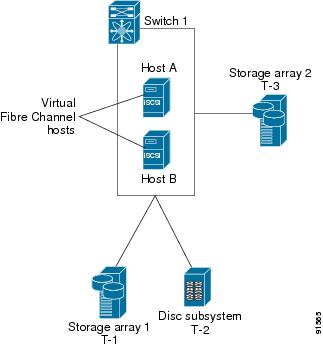
In conjunction with presenting Fibre Channel targets to iSCSI hosts, the IPS module presents each iSCSI host as a Fibre Channel host (in transparent mode), that is, a host bus adapter (HBA) to the Fibre Channel storage device. The storage device responds to each IP host as if it were a Fibre Channel host connected to the Fibre Channel network (see Figure 20-3).
Figure 20-3 Fibre Channel SAN View
Note
Routing iSCSI Requests and Responses
The iSCSI feature consists of routing iSCSI requests and responses between hosts in an IP network and Fibre Channel storage devices in the Fibre Channel SAN that are accessible from any Fibre Channel interface of the Cisco MDS 9000 Family switch (see Figure 20-4).
Figure 20-4 Routing iSCSI Requests and Responses for Transparent iSCSI Routing
Each iSCSI host that requires access to storage through the IPS module needs to have a compatible iSCSI driver installed. (The Cisco.com website at http://www.cisco.com/public/sw-center/sw-stornet.shtml provides a list of compatible drivers). Using the iSCSI protocol, the iSCSI driver allows an iSCSI host to transport SCSI requests and responses over an IP network. From the host operating system perspective, the iSCSI driver appears to be a SCSI transport driver similar to a Fibre Channel driver for a peripheral channel in the host. From the storage device perspective, each IP host appears as a Fibre Channel host.
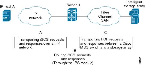
Routing SCSI from the IP host to the Fibre Channel storage device consists of the following main actions (see Figure 20-5):
•
•
•
Figure 20-5 Transparent SCSI Routing Actions
Note
Enabling iSCSI
To begin configuring the iSCSI feature, you must explicitly enable iSCSI on the required switches in the fabric. By default, this feature is disabled in all switches in the Cisco MDS 9000 Family.
The configuration and verification commands for the iSCSI feature are only available when iSCSI is enabled on a switch. When you disable this feature, all related configurations are automatically discarded.
To enable iSCSI on a switch using Fabric Manager, follow these steps:
Step 1
Step 2
Step 3
Step 4
Using the iSCSI Wizard
To use the iSCSI wizard in Fabric Manager, follow these steps:
Step 1
Step 2
Step 3
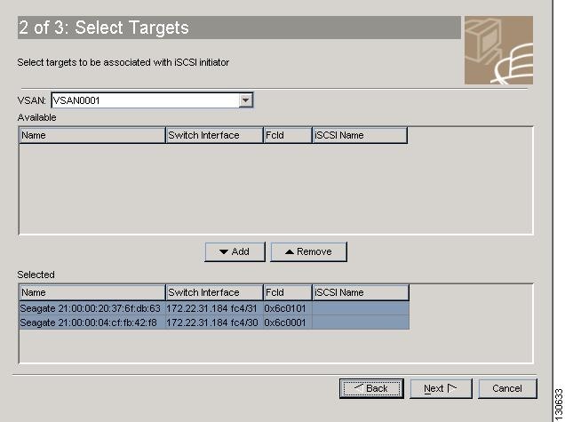
Step 4
Figure 20-6 Select Targets
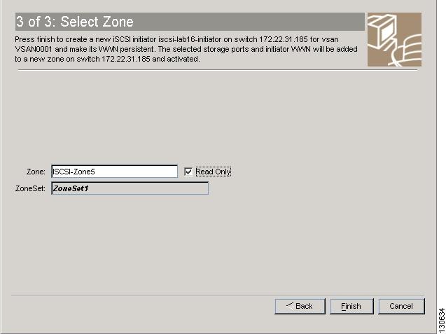
Step 5
Figure 20-7 Select Zone
Step 6
Presenting Fibre Channel Targets as iSCSI Targets
The IPS module presents physical Fibre Channel targets as iSCSI targets allowing them to be accessed by iSCSI hosts. It does this in one of two ways:
•
•
Note
Dynamically Importing Fibre Channel Targets
The IPS module maps each physical Fibre Channel target port as one iSCSI target. That is, all LUs accessible through the physical storage target port are available as iSCSI LUs with the same LU number (LUN) as in the storage target.
For example, if an iSCSI target was created for a Fibre Channel target port with pWWN 31:00:11:22:33:44:55:66 and that pWWN contains LUN 0 through 2, those LUNs would become available to an IP host as LUNs 0 through 2 as well.
Note
The iSCSI target node name is created automatically using the iSCSI qualified name (IQN) format. The iSCSI qualified name is restricted to a maximum name length of 223 alphanumeric characters and a minimum length of 16 characters.
The IPS module creates an IQN formatted iSCSI node name using the following conventions:
•
iqn.1987-05.com.cisco:05.<mgmt-ip-address>.<slot#>-<port#>-<sub-intf#>.<Target-pWWN>•
iqn.1987-05.com.cisco:05.vrrp-<vrrp-ID#>-<vrrp-IP-addr>.<Target-pWWN>•
iqn.1987-02.com.cisco:05.<mgmt-ip-address>.pc-<port-ch-sub-intf#>.<Target-pWWN>
Note
Configuring Dynamic Importing with Device Manager
To dynamically import Fibre Channel targets as iSCSI targets, follow these steps:
Step 1
Step 2
Step 3
Step 4
Creating a Static iSCSI Virtual Target
You can manually (statically) create an iSCSI target and assign a node name to it. A statically mapped iSCSI target can either contain the whole FC target port, or it can contain one or more LUs from a Fibre Channel target port.
You can limit the Gigabit Ethernet interfaces over which static iSCSI targets are advertised. By default iSCSI targets are advertised on all Gigabit Ethernet interfaces, subinterfaces, PortChannel interfaces, and PortChannel subinterfaces.
To create a static iSCSI virtual target for the Fibre Channel target port, follow these steps
Step 1
Step 2
Step 3
Step 4
Step 5
Step 6
Step 7
Step 8
See the "iSCSI-Based Access Control" section for more information on controlling access to statically imported targets.
For multiple interfaces configured with iSNS (see the "Configuring iSCSI Storage Name Services" section), a different static virtual target name has to be created for each interface tagged to an iSNS profile and each static virtual target must be advertised only from one interface (see the "Configuring iSCSI Storage Name Services" section).
High Availability Static Target Importing
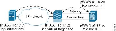
Statically imported iSCSI targets have an additional option to provide a secondary pWWN for the Fibre Channel target. This can be used when the physical Fibre Channel target is configured to have an LU visible across redundant ports. When the active port fails, the secondary port becomes active and the iSCSI session switches to use the new active port (see Figure 20-8).
Figure 20-8 Static Target Importing Through Two Fibre Channel Ports
In Figure 20-8, you can create a virtual iSCSI target that is mapped to both pWWN1 and pWWN2 to provide redundant access to the Fibre Channel targets.
The failover to secondary port is done transparently by the IPS port without impacting the iSCSI session from the host. All outstanding I/O are terminated with a check condition status when the primary port fails. New I/O received while the failover has not completed will receive a busy status.
Tip
Refer to the Cisco MDS 9000 Family Configuration Guide for details on setting the secondary pWWN.
Enable the revert to primary port option to direct the IPS port to switch back to the primary port when the primary port is up again. If this option is disabled (default) and the primary port is up again after a switchover, the old sessions will remain with the secondary port and does not switch back to the primary port. However, any new session will use the primary port. This is the only situation when both the primary and secondary ports are used at the same time.
To enable the revert to primary port option, follow these steps:
Step 1
From Device Manager, choose IP > iSCSI. You see the iSCSI dialog box.
Step 2
Step 3
Step 4
Step 5
Configuring the Trespass Feature
In addition to the high availability of statically imported iSCSI targets, the trespass feature is available (as of Cisco MDS SAN-OS Release 1.3(x)) to enable the export of LUs, on an active port failure, from the active to the passive port of a statically imported iSCSI target.
In physical Fibre Channel targets, which are configured to have LUs visible over two Fibre Channel N-ports, when the active port fails, the passive port takes over. Some physical Fibre Channel targets require that the trespass command be issued to export the LUs from the active port to the passive port. A statically imported iSCSI target's secondary pWWN option and an additional option of enabling the trespass feature is available for a physical Fibre Channel target with redundant ports. When the active port fails, the passive port becomes active, and if the trespass feature is enabled, the Cisco MDS switch issues a trespass command to the target to export the LUs on the new active port. The iSCSI session switches to use the new active port and the exported LUs are accessed over the new active port (see Figure 20-9).
Figure 20-9 Virtual Target with an Active Primary Port
To configure the trespass feature, follow these steps:
Step 1
From Device Manager, choose IP > iSCSI. You see the iSCSI dialog box.
Step 2
Step 3
Step 4
Presenting iSCSI Hosts as Virtual Fibre Channel Hosts
The iSCSI hosts are mapped to virtual Fibre Channel hosts in one of two ways (see Figure 20-3):
•
•
Dynamic Mapping
When an iSCSI host connects to the IPS module using the iSCSI protocol, a virtual N port is created for the host. The nWWNs and pWWNs are dynamically allocated from the switch's Fibre Channel WWN pool. The IPS module registers this N port in the Fibre Channel SAN. The IPS module continues using that nWWN and pWWN to represent this iSCSI host until it no longer has a connection to any iSCSI target through that IP storage port.
At that point, the virtual Fibre Channel host is taken offline from the Fibre Channel SAN and the nWWNs and pWWNs are released back to the switch's Fibre Channel WWN pool. These addresses become available for assignment to other iSCSI hosts requiring access to Fibre Channel SANs. When a dynamically mapped iSCSI initiator has multiple sessions to multiple Fibre Channel targets, each session can use the same pWWN and nWWN as long as it uses the same node name in the iSCSI login message.
Initiator Identification
By default, the switch uses the iSCSI node name to identify the initiator.
An iSCSI initiator is identified in one of two ways:
•
•
Static Mapping
Use the static mapping method to obtain the same nWWN and pWWNs for the iSCSI host each time it connects to the IPS module.
Static mapping can be used on the IPS module to access intelligent Fibre Channel storage arrays that have access control and LUN mapping or masking configuration based on the initiator's pWWNs and/or nWWNs.
Note
You can implement static mapping in one of two ways:
•
•
Tip
Note
Assigning VSAN Membership to iSCSI Hosts
By default, a host is only in VSAN 1 (default VSAN). You can configure an iSCSI host to be a member of one or more VSANs. The IPS module creates one Fibre Channel virtual N port in each VSAN to which the host belongs.
Note
All dynamic iSCSI initiators are members of VSAN 1. The port VSAN of an iSCSI interface is the default VSAN for all dynamic iSCSI initiators. All dynamic iSCSI initiators are members of the port VSAN of the iSCSI interface. The default port VSAN of an iSCSI interface is VSAN 1.
To modify the VSANs assigned to an iSCSI interface using Device Manager, follow these steps:
Step 1
Step 2
Step 3
Step 4
Creating a Statically Mapped iSCSI Initiator
To create a statically mapped iSCSI initiator using Device Manager, follow these steps:
Step 1
Step 2
Step 3
Step 4
Step 5
Step 6
Step 7
Step 8
Or leave this unchecked and set one or more pWWNs for this iSCSI initiator.Step 9
Step 10
iSCSI Proxy Initiators
Note
By default, each iSCSI initiator appears as one Fibre Channel initiator in transparent mode in the Fibre Channel fabric. For some storage arrays, this appearance requires the initiator's pWWN to be manually configured for access control purposes. This process can be quite cumbersome. The proxy initiator feature allows all iSCSI initiators to connect through one IPS port making it appear as one Fibre Channel port per VSAN. It simplifies the task of configuring the pWWN for each new initiator on the storage array, and of configuring Fibre Channel access control such as zoning. This feature along with static target importing (using LUN mapping) results in the configuration being performed only on the switch when a new iSCSI host is added. On the storage array, all LUNs that are used by iSCSI initiators are configured to allow access by the proxy initiator's pWWN. From the iSCSI perspective, this configuration is no different from the default mode (see Figure 20-10).
Figure 20-10 iSCSI View of a Proxy Initiator
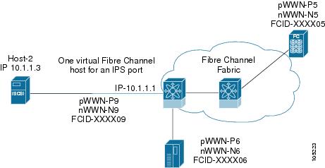
From the Fibre Channel perspective, only one Fibre Channel initiator is visible per VSAN (see Figure 20-11).
Figure 20-11 Fibre Channel View with a Proxy Initiator
Configuring the iSCSI Proxy Initiator
To configure the proxy initiator, follow these steps:
Step 1
From Device Manager, select Interfaces > Ethernet or iSCSI. You see the interfaces dialog box.
Step 2
Step 3
Step 4
Access Control in iSCSI
You can control access to each statically mapped iSCSI target by specifying a list of IPS ports on which it is advertised and specifying a list of iSCSI initiator node names allowed to access it. Fibre Channel zoning-based access control and iSCSI-based access control are the two mechanisms by which access control can be provided for iSCSI. Both methods can be used simultaneously.
Note
Fibre Channel Zoning-Based Access Control
Zoning is an access control mechanism within a VSAN. The zoning implementation on the switch extends the VSAN and zoning concepts from the Fibre Channel domain to cover the iSCSI domain. This extension includes both iSCSI and Fibre Channel features and provides a uniform, flexible access control across a SAN. There are two Fibre Channel zoning access control mechanisms--static and dynamic.
•
•
To register an iSCSI host initiator as a member of a zone using Fabric Manager, follow these steps:
Step 1
Step 2
Step 3
Step 4
iSCSI-Based Access Control
For static iSCSI targets, you can manually configure a list of iSCSI initiators that are allowed to access the targets. The iSCSI initiator is identified by the iSCSI node name or the IP address of the iSCSI host.
By default, static virtual iSCSI targets are not accessible to any iSCSI host. You must explicitly configure accessibility to allow a virtual iSCSI target to be accessed by all hosts. The initiator access list can contain one or more initiators. Each initiator is identified by one of the following:
•
•
•
See the "Creating a Static iSCSI Virtual Target" section to configure access control using a list of authorized initiators.
Enforcing Access Control
IPS modules use both iSCSI node name-based and Fibre Channel zoning-based access control lists to enforce access control during iSCSI discovery and iSCSI session creation.
•
•
The IPS module then creates a Fibre Channel virtual N port (the N port may already exist) for this IP host and does a Fibre Channel name server query for the FCID of the Fibre Channel target pWWN that is being accessed by the IP host. It uses the IP host virtual N port's pWWN as the requester of the name server query. Thus, the name server does a zone-enforced query for the pWWN and responds to the query.
If the FCID is returned by the name server, then the iSCSI session is accepted. Otherwise, the login request is rejected.
Note
iSCSI User Authentication
The IPS module supports the iSCSI authentication mechanism to authenticate iSCSI hosts that request access to storage. When iSCSI authentication is enabled, the iSCSI hosts must provide user name and password information each time an iSCSI session is established.
Note
No Authentication
If no authentication is configured, local authentication is used.
Set the iSCSI authentication method to none to configure a network with no authentication. See the "Configuring an Authentication Mechanism" section.
Configuring an Authentication Mechanism
During an iSCSI login, both the iSCSI initiator and target have the option to authenticate each other. By default, the IPS module allows either CHAP authentication or no authentication from iSCSI hosts.
Note
To configure an authentication method for iSCSI, follow these steps:
Step 1
In Device Manager, select IP > iSCSI. You see the iSCSI dialog box.Step 2
Step 3
Or in Device manager, check the Chap check box to configure DH-CHAP authentication, or check none for no authentication.Step 4
Restricting iSCSI Initiator Authentication
By default, the iSCSI initiator can use any user name in RADIUS or local database in authenticating itself to the IPS module or MPS-14/2 module (the CHAP user name is independent of the iSCSI initiator name). The IPS module or MPS-14/2 module allows the initiator to login as long as it provides a correct response to the CHAP challenge sent by the switch. This can be a problem if one CHAP user name and password had been compromised.
To restrict an initiator to use a specific user name for CHAP authentication using Device Manager, follow these steps:
Step 1
Step 2
Step 3
Mutual CHAP Authentication
In addition to the IPS module or MPS-14/2 module authentication of the iSCSI initiator, the IPS module or MPS-14/2 module also supports a mechanism for the iSCSI initiator to authenticate the Cisco MDS switch's iSCSI target during the iSCSI login phase. This authentication requires the user to configure a username and password for the switch to present to the iSCSI initiator. The provided password is used to calculate a CHAP response to a CHAP challenge sent to the IPS port by the initiator.
To configure a global iSCSI target username and password to be used by the switch to authenticate itself to an initiator using Device Manager, follow these steps
Step 1
Step 2
Step 3
To configure a per-initiator iSCSI target's user name and password used by the switch to authenticate itself to an initiator using Device Manager, follow these steps:
Step 1
Step 2
Step 3
Configuring an iSCSI RADIUS Server
To configure an iSCSI RADIUS server, follow these steps:
Step 1
Step 2
Step 3
Advanced iSCSI Configuration
Advanced configuration options are available for iSCSI interfaces on a per-IPS port basis.Cisco MDS switches support the following advanced features for iSCSI interfaces:
•
See the )
•
–
–
•
•
Setting the QoS Values
To set the QoS values, follow these steps:
Step 1
In Device Manager, select Interfaces > Ethernet or iSCSI. You see the interfaces dialog box.Step 2
Step 3
Step 4
iSCSI Forwarding Mode
The iSCSI gateway on the IPS module has two modes of forwarding operation:
•
is done during iSCSI login and FC PLOGI and the value is restricted by the TCP connection's maximum segment size (MSS) and the maximum Fibre Channel data payload size specified by the FC target. This usually results in a smaller maximum payload size than most hosts expect,
thus comes the second mode of forwarding.•
iSCSI High Availability
The following high availability features are available for iSCSI configurations:
•
•
Multiple IPS Ports Connected to the Same IP Network
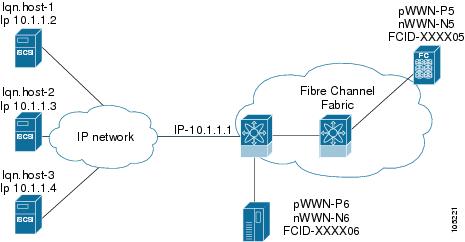
Figure 20-12 provides an example of a configuration with multiple Gigabit Ethernet interfaces in the same IP network.
Figure 20-12 Multiple Gigabit Ethernet Interfaces in the Same IP Network
In Figure 20-12, each iSCSI host discovers two iSCSI targets for every physical Fibre Channel target (with different names). The multi-pathing software on the host provides load-balancing over both paths. If one Gigabit Ethernet interface fails, the host multi-pathing software is not affected because it can use the second path.
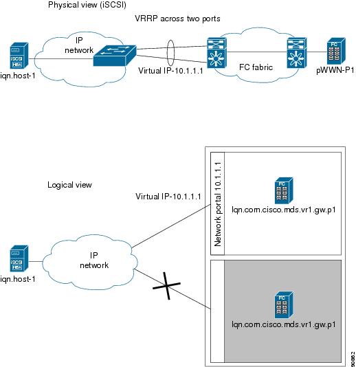
VRRP-Based High Availability
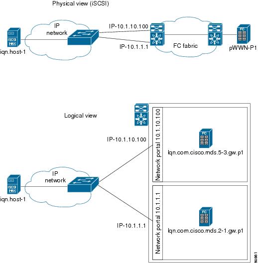
Figure 20-13 provides an example of a VRRP-based high availability iSCSI configuration.
Figure 20-13 VRRP-Based iSCSI High Availability
In Figure 20-13, each iSCSI host discovers one iSCSI target for every physical Fibre Channel target. When the Gigabit Ethernet interface of the VRRP master fails, the iSCSI session is terminated. The host then reconnects to the target and the session comes up because the second Gigabit Ethernet interface has taken over the virtual IP address as the new master.
Tip
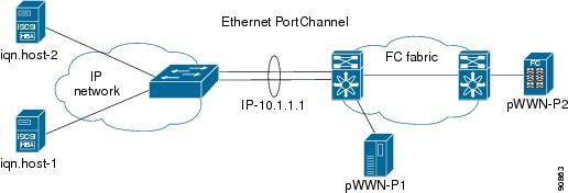
Ethernet PortChannel-Based High Availability
Note
Figure 20-14 provides a sample Ethernet PortChannel-based high availability iSCSI configuration.
Figure 20-14 Ethernet PortChannel-Based iSCSI High Availability
In Figure 20-14, each iSCSI host discovers one iSCSI target for every physical Fibre Channel target. The iSCSI session from the iSCSI host to the virtual iSCSI target (on the IPS port) uses one of the two physical interfaces (because an iSCSI session uses one TCP connection). When the Gigabit Ethernet interface fails, the IPS module and the Ethernet switch transparently forwards all the frames on to the second Gigabit Ethernet interface.
Configuring iSCSI Storage Name Services
The Internet Storage Name Service (iSNS) client and server features are available in all switches in the Cisco MDS 9000 Family with IPS modules installed.
iSNS services allow your existing TCP/IP networks to function more effectively as storage area networks by automating the discover and management of iSCSI devices. To facilitate these functions, the iSNS client functionality registers iSCSI portals and all targets accessible through a particular interface with an external iSNS server.
This section includes the following topics:
•
Note
iSNS Client Functionality
The iSNS client functionality on each interface (Gigabit Ethernet interface or subinterface or PortChannel) registers information with its configured iSNS server using an iSNS profile. This process is referred to as tagging an iSNS profile to an interface. Each iSNS profile keeps information about an iSNS server IP address. One profile can be tagged to one or more interfaces.
Once a profile is tagged to an interface, the MDS switch opens a TCP connection to the iSNS server IP address (using a well-known iSNS port number 3205) in the profile and registers network entity and portal objects. It goes through the FC name server database and configuration to find storage nodes to register with the server.
Statically mapped virtual targets are registered if the associated Fibre channel pWWN is present in the FC name server database and no access control configuration prevents it. A dynamically mapped target is registered if the dynamic target importing is enabled. See the "Using the iSCSI Wizard" section.
A storage node is deregistered from the iSNS server when it becomes unavailable either because of configuration changes (such as access control change or dynamic import disabling) or when the Fibre Channel storage port goes off-line. It is registered again when the node is online.
When the iSNS client is unable to register/deregister objects with the iSNS server (for example, the client is unable to make a TCP connection to the iSNS server), it retries every minute to re-register all iSNS objects for the affected interface(s) with the iSNS server.
Untagging a profile causes the network entity and portal to deregister from that interface.
Creating an iSNS Profile
To create an iSNS profile, follow these steps:
Step 1
In Device Manager, select IP > iSCSI. You see the iSCSI dialog box.Step 2
Step 3
Step 4
Modifying an iSNS Profile
To modify (tag) the iSNS profile for an interface, untag the interface from the currently tagged iSNS profile and then tag to a new iSNS profile.
To tag an interface to a profile using Device Manager, follow these steps:
Step 1
Step 2
Step 3
Step 4
Enabling the iSNS Server
Before enabling the iSNS server feature, you must enable iSCSI. (See the "Enabling iSCSI" section.) If you disable iSCSI, then iSNS is automatically disabled. If you enable an iSNS server on a switch, then every IPS port whose corresponding iSCSI interface is up can service iSNS registration and query requests from external iSNS clients.
To enable the iSNS server, follow these steps:
Step 1
You see the iSNS servers in the Information pane.
Step 2
Step 3
Step 4
Configuring the ESI Retry Count
The iSNS client registers information with its configured iSNS server using an iSNS profile. At registration, the client can indicate an entity status inquiry (ESI) interval of 60 seconds or more. If the client registers with an ESI interval set to zero, then the server does not monitor the client using ESI. In such cases, the client's registrations remain valid until explicitly deregistered or the iSNS server feature is disabled.
The ESI retry count (labelled as the ESI Non-Resp Threshold in the Fabric Manager interface) is the number of times the iSNS server queries iSNS clients for their entity status. The default ESI retry count is 3. The client sends the server a response to indicate that it is still alive. If the client fails to respond after a configured number of retries, the client is deregistered from the server.
To configure the ESI retry count for an iSNS server, follow these steps:
Step 1
You see the iSNS servers in the Information pane.
Step 2
Step 3
Step 4