Cisco MDS 9000 Family Fabric Manager Configuration Guide, Release 2.x
Inter-VSAN Routing Configuration

Table Of Contents

Inter-VSAN Routing Configuration

Inter-VSAN Routing

Understanding IVR

IVR Terminology

Fibre Channel Header Modifications

IVR NAT

IVR VSAN Topology

Autonomous Fabric ID

Service Groups

Using IVR NAT and Auto Topology

Transit VSAN Guidelines

Border Switch Guidelines

Service Group Guidelines

Using IVR Without IVR NAT or Auto Topology

Domain ID Guidelines

Transit VSAN Guidelines

Border Switch Guidelines

Using the IVR Zone Wizard

Modifying IVR

Modifying IVR NAT and IVR Auto Topology

Configuring Service Group

Configuring AFIDs

Enabling IVR Without NAT

Manually Creating the IVR Topology

Activating an IVR Topology

Clearing the IVR Topology

Adding IVR Virtual Domains

IVR Zones and IVR Zone Sets

IVR Zones Versus Zones

Automatic IVR Zone Creation

Configuring IVR Zones and Zone Sets

Creating Additional IVR Zones and Zone Sets

Activating IVR Zone Sets

Deactivating IVR Zone Sets

Recovering an IVR Full Zone Database

Recovering an IVR Full Topology

Adding Members to IVR Zones

IVR Interoperability


Inter-VSAN Routing Configuration


This chapter explains the inter-VSAN routing (IVR) feature and provides details on sharing resources across VSANs using IVR management interfaces provided in the switch.

This chapter includes the following sections:

Inter-VSAN Routing

Using the IVR Zone Wizard

Modifying IVR

Enabling IVR Without NAT

IVR Zones and IVR Zone Sets

IVR Interoperability

Inter-VSAN Routing

Virtual SANs (VSANs) improve storage area network (SAN) scalability, availability, and security by allowing multiple Fibre Channel SANs to share a common physical infrastructure of switches and ISLs. These benefits are derived from the separation of Fibre Channel services in each VSAN and isolation of traffic between VSANs. Data traffic isolation between the VSANs also inherently prevents sharing of resources attached to a VSAN, like robotic tape libraries. Using IVR, resources across VSANs are accessed without compromising other VSAN benefits.

This section includes the following topics:

Understanding IVR

IVR Terminology

Fibre Channel Header Modifications

IVR NAT

IVR VSAN Topology

Understanding IVR

Data traffic is transported between specific initiators and targets on different VSANs without merging VSANs into a single logical fabric. Fibre Channel control traffic does not flow between VSANs, nor can initiators access any resource across VSANs aside from the designated ones. Valuable resources such as tape libraries are easily shared across VSANs without compromise.

IVR is in compliance with Fibre Channel standards and incorporates third-party switches, however, IVR-enabled VSANs may have to be configured in one of the interop modes.

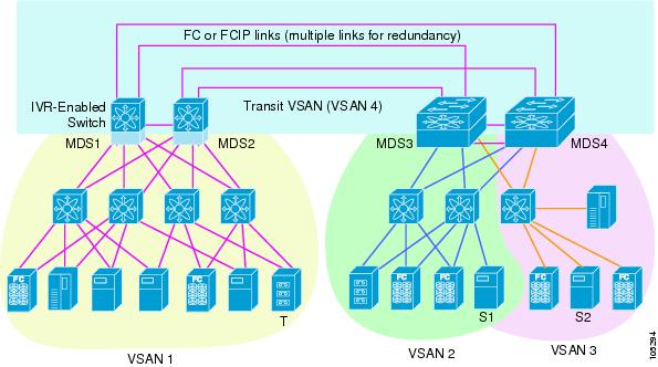
IVR is not limited to VSANs present on a common switch. Routes that traverse one or more VSANs across multiple switches can be established, if necessary, to establish proper interconnections. IVR used in conjunction with FCIP provides more efficient business continuity or disaster recovery solutions (see Figure 16-1).

Figure 16-1 Traffic Continuity Using IVR and FCIP

IVR Terminology

The following terms are used in this chapter.

Native VSAN—The VSAN to which an end device logs on is the native VSAN for that end device.

Inter-VSAN zone (IVR zone)—A set of end devices that are allowed to communicate across VSANs within their interconnected SAN fabric. This definition is based on their port world wide names (pWWNs) and their native VSAN associations. You can configure up to 2,000 IVR zones and10,000 IVR zone members in the fabric from any switch in the Cisco MDS 9000 Family.

Inter-VSAN zone sets (IVR zone sets)—One or more IVR zones make up an IVR zone set. You can configure up to 32 IVR zone sets on any switch in the Cisco MDS 9000 Family. Only one IVR zone set can be active at any time.

IVR path—An IVR path is a set of switches and Inter-Switch Links (ISLs) through which a frame from one end-device in one VSAN can reach another end-device in some other VSAN. Multiple paths can exist between two such end-devices.

IVR-enabled switch—A switch in which the IVR feature is enabled.

Edge VSAN—A VSAN that initiates (source edge-VSAN) or terminates (destination edge-VSAN) an IVR path. Edge VSANs may be adjacent to each other or they may be connected by one or more transit VSANs. In Figure 16-1, VSANs 1, 2, and 3 are edge VSANs.


Note An edge VSAN for one IVR path can be a transit VSAN for another IVR path.


Transit VSAN—A VSAN that exists along an IVR path from the source edge VSAN of that path to the destination edge VSAN of that path. In Figure 16-1, VSAN 4 is a transit VSAN.


Note When the source and destination edge VSANs are adjacent to each other, then a transit VSAN is not required between them.


Border switch—An IVR-enabled switch that is a member of two or more VSANs. Border switches in Figure 16-1 span two or more different color-coded VSANs.

Edge switch—A switch to which a member of an IVR zone has logged in. Edge switches are oblivious to the IVR configurations in the border switches. Edge switches need not be IVR enabled.

Fibre Channel Header Modifications

IVR works by virtualizing the remote end devices in the native VSAN using a virtual domain. When IVR is configured to link end devices in two disparate VSANs, the IVR border switches are responsible for modifying the Fibre Channel headers for all communication between the end devices. The sections of the Fibre Channel frame headers that are modified include:

VSAN number

Source FCID

Destination FCID

When a frame goes from the initiator to the target, the Fibre Channel frame header is modified such that the initiator VSAN number is changed to the target VSAN number. If IVR Network Address Translation (NAT) is enabled, then the source and destination FCIDs are also translated at the edge border switch. If IVR NAT is not enabled, then you must configure unique domain IDs for all switches involved in the IVR path.

IVR NAT

Cisco MDS SAN-OS Release 2.1(1a) introduces IVR NAT, which allows you to set up IVR in a fabric without needing unique domain IDs on every switch in the IVR path. When IVR NAT is enabled, the virtualized end device that appears in the native VSAN uses a virtual domain ID that is unique to the native VSAN.


Note IVR NAT requires Cisco MDS SAN-OS Release 2.1(1a) or later on all switches in the fabric performing IVR. If you have isolated switches with an earlier release that are involved in IVR, you must remove any isolated fabrics from monitoring by Fabric Manager server and then re-open the fabric to use IVR NAT.


Note Load balancing of IVR NAT traffic across equal cost paths from an IVR-enabled switch is not supported. However, load balancing of IVR NAT traffic over PortChannel links is supported.


IVR VSAN Topology

IVR uses a configured IVR VSAN topology to determine how to route traffic between the initiator and the target across the fabric. You can configure this IVR VSAN topology manually on an IVR-enabled switch and distribute the configuration using CFS in Cisco MDS SAN-OS Release 2.0(1b) or later. Alternately, in Cisco MDS SAN-OS Release 2.1(1a) or later, you can configure IVR topology in auto mode. Prior to Cisco MDS SAN-OS Release 2.0(1b), you need to manually copy the IVR VSAN topology to each switch in the fabric.

Auto mode automatically builds the IVR VSAN topology and maintains the topology database when fabric reconfigurations occur. Auto mode distributes the IVR VSAN topology to IVR-enabled switches using CFS.

Using auto mode, you no longer need to manually update the IVR VSAN topology when reconfigurations occur in your fabric. If a manually configured IVR topology database exists, auto mode initially uses that topology information. This reduces disruption in the network by gradually migrating from the user-specified topology database to the automatically learned topology database. User configured topology entries that are not part of the network are aged out in about three minutes. New entries that are not part of the user configured database are added as they are learned from the network.


Note IVR topology in auto mode requires Cisco MDS SAN-OS Release 2.1(1a) or later and enabling CFS for IVR on all switches in the fabric.


Autonomous Fabric ID

The autonomous fabric ID (AFID) distinguishes segmented VSANS (that is, two VSANs that are logically and physically separate but have the same VSAN number). Cisco MDS SAN-OS Release 2.1(1a) introduces support for AFIDs from 1 through 64. AFIDs are used in conjunction with auto mode to allow segmented VSANS in the IVR VSAN topology database. You can configure up to 64 AFIDs.

The AFID can be configured individually for each switch and list of VSANs, or the default AFID can be configured for each switch.


Note Two VSANs with the same VSAN number but different AFIDs are counted as two VSANs out of the total 128 VSANs allowed in the fabric.


Service Groups

Cisco MDS SAN-OS Release 2.1(1a) introduces service groups as a way to limit the control traffic associated with distributing the IVR VSAN topology learned in auto mode. A services group lists AFIDs and the VSANs associated with each AFID. When the IVR configuration is distributed, CFS uses the service group to limit the number of switches to which it sends the new IVR VSAN topology database. Currently, you can configure one service group for the fabric.


Note You must update the service group and distribute it using CFS whenever a fabric reconfiguration affects an IVR-enabled switch.


Using IVR NAT and Auto Topology

Before configuring an IVR SAN fabric to use IVR NAT and auto-topology, consider the following guidelines:

Configure IVR only in the relevant switches.

Enable CFS for IVR on all switches in the fabric.

Verify all switches in the fabric are running Cisco MDS SAN-OS Release 2.1(1a) or later.

Acquire a mandatory Enterprise License Package or SAN-EXTENSION license package if you have Cisco MDS SAN-OS Release2.1(1a) or later and one active IPS card for this feature.


Note IVR is bundled with the Cisco MDS 9216i switch and does not require a license.


Tip If you change any FSPF link cost, ensure that the FSPF path distance (that is, the sum of the link costs on the path) of any IVR path is less than 30,000.


Note IVR-enabled VSANs can be configured when the interop mode is enabled (any interop mode) or disabled (no interop mode).


Note In an IVR NAT configuration, if one VSAN in the IVR topology is configured with static domain IDs, then the IVR domains that can be exported to that VSAN must also be assigned static domains.


Transit VSAN Guidelines

Consider the following guidelines for transit VSANs:

Besides defining the IVR zone membership, you can choose to specify a set of transit VSANs to provide connectivity between two edge VSANs:

If two edge VSANs in an IVR zone overlap, then a transit VSAN is not required (though, not prohibited) to provide connectivity.

If two edge VSANs in an IVR zone do not overlap, you may need one or more transit VSANs to provide connectivity. Two edge VSANs in an IVR zone will not overlap if IVR is not enabled on a switch that is a member of both the source and destination edge VSANs.

Traffic between the edge VSANs only traverses through the shortest IVR path.

Transit VSAN information is common to all IVR zone sets. Sometimes, a transit VSAN can also double-up as an edge VSAN in another IVR zone.

Border Switch Guidelines

Before configuring border switches, consider the following guidelines:

Border switches require Cisco MDS SAN-OS Release 2.1(1a) or later.

A border switch must be a member of two or more VSANs.

A border switch that facilities IVR communications must be IVR enabled.

IVR can (optionally) be enabled on additional border switches to provide redundant paths between active IVR zone members.

The VSAN topology configuration updates automatically when a border switch is added or removed.

Service Group Guidelines

If you use service groups with IVR auto topology, you should enable IVR and configure your service group first, then distribute them with CFS before setting the IVR topology in auto mode.

Using IVR Without IVR NAT or Auto Topology

Before configuring an IVR SAN fabric without IVR in NAT mode or IVR topology in auto mode, consider the following guidelines:

Configure unique domain IDs across all VSANs and switches participating in IVR operations if you are not using IVR NAT. The following switches participate in IVR operations:

All edge switches in the edge VSANs (source and destination)

All switches in transit VSANs

Configure IVR only in the relevant border switches.

Acquire a mandatory Enterprise License Package or SAN-EXTENSION license package if you have Cisco MDS SAN-OS Release2.1(1a) or later and one active IPS card for this feature.


Tip If you change any FSPF link cost, ensure that the FSPF path distance (that is, the sum of the link costs on the path) of any IVR path is less than 30,000.


Note IVR-enabled VSANs can be configured when the interop mode is enabled (any interop mode) or disabled (no interop mode).


Domain ID Guidelines

Domain IDs must be unique across inter-connected VSANs when not using IVR NAT. To ensure unique domain IDs across inter-connected VSANs, consider these guidelines:

Minimize the number of switches that require a domain ID assignment. This ensures minimum traffic disruption.

Minimize the coordination between interconnected VSANs when configuring the SAN for the first time as well as when you add each new switch.

You can configure domain IDs using one of two options:

Configure the allowed-domains list so that the domains in different VSANs are non-overlapping on all participating switches and VSANs.

Configure static, non-overlapping domains for each participating switch and VSAN.


Note In a configuration involving IVR without NAT, if one VSAN in the IVR topology is configured with static domain IDs, then the other VSANs (edge or transit) in the topology should has to be configured with static domain IDs.


Transit VSAN Guidelines

Before configuring transit VSANS, consider the following guidelines:

Besides defining the IVR zone membership, you can choose to specify a set of transit VSANs to provide connectivity between two edge VSANs:

If two edge VSANs in an IVR zone overlap, then a transit VSAN is not required (though, not prohibited) to provide connectivity.

If two edge VSANs in an IVR zone do not overlap, you may need one or more transit VSANs to provide connectivity. Two edge VSANs in an IVR zone will not overlap if IVR is not enabled on a switch that is a member of both the source and destination edge VSANs.

Traffic between the edge VSANs only traverses through the shortest IVR path.

Transit VSAN information is common to all IVR zone sets. Sometimes, a transit VSAN can also double-up as an edge VSAN in another IVR zone.

Border Switch Guidelines

Before configuring border switches, consider the following guidelines:

Border switches require Cisco MDS SAN-OS Release 1.3(1) or later.

A border switch must be a member of two or more VSANs.

A border switch that facilities IVR communications must be IVR enabled.

IVR can (optionally) be enabled on additional border switches to provide redundant paths between active IVR zone members.

The VSAN topology configuration must be updated before a border switch is added or removed.

Using the IVR Zone Wizard

The IVR Zone Wizard simplifies the steps required to configure IVR zones in a fabric. The IVR Zone Wizard checks the following conditions and prompts you for any issues:

Checks if all switches in the fabric are Cisco MDS SAN-OS Release 2.1(1a) or later and if so, asks if you want to migrate to using IVR NAT with auto-topology.

Checks if any switches in the fabric are earlier than Cisco MDS SAN-OS Release 2.1(1a) and if so, asks you to upgrade the necessary switches or to disable IVR NAT or auto-topology if they are enabled.

To use the IVR Zone Wizard to configure IVR and IVR zones, follow these steps:
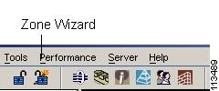

Step 1 From Fabric Manager, click the IVR Zone Wizard icon in the Zone toolbar. Figure 16-2 shows the IVR Zone Wizard icon.

Figure 16-2 IVR Zone Wizard Icon

You see the IVR Zone Wizard.

Step 2 Select the VSANs that will participate in IVR in the fabric.

Step 3 Select the end devices that you want to communicate over IVR.


Note If you are not using IVR NAT, Fabric Manager may display an error message if all the switches participating in IVR do not have unique domain IDs. You must reconfigure those switches before configuring IVR.


Step 4 If you enable IVR NAT, verify switches that Fabric Manager will enable with IVR NAT, CFS for IVR, and IVR topology in auto mode.

Step 5 Optionally, configure a unique AFID for switches in the fabric that have non-unique VSAN IDs in the Select AFID dialog box.

Step 6 If you did not enable IVR NAT, verify the transit VSAN or configure the transit VSAN if Fabric Manager cannot find an appropriate transit VSAN.

Step 7 Set the IVR zone and IVR zone set.

Step 8 Verify all steps that Fabric Manager will take to configure IVR in the fabric.

Step 9 Click Finish if you want to enable IVR NAT and IVR topology and create the associated IVR zones and IVR zone set, or click Cancel to exit the IVR Wizard without saving any changes.


Note IVR NAT and auto-topology can be configured independently if you configure these features outside the IVR Zone Wizard. See the "Modifying IVR" section.


Modifying IVR

You can modify IVR using the IVR tables in the Information pane in Fabric Manager. Use these tables only if you are familiar with all IVR concepts. We recommend you configure IVR using the IVR Wizard.


Note Most tabs in the Information pane for features using CFS are dimmed until you click the CFS tab. The CFS tab shows which switches have CFS enabled and shows the master switch for this feature. Once the CFS tab is clicked, the other tabs in the Information pane are activated.


Modifying IVR NAT and IVR Auto Topology

To modify IVR in NAT mode and IVR topology in auto mode from Fabric Manager, follow these steps:


Step 1 Select All VSANs > IVR from the Logical Domains pane.You see the IVR configuration in the Information pane.

Step 2 Select the CFS tab if CFS is enabled for this feature in the fabric.

Step 3 Select enable from the Enable/Admin column for the primary switch.

Step 4 Select the Apply Changes button from the Information pane to distribute this change to all switches in the fabric, or select the Undo Changes button to cancel any changes you made.

Step 5 Select the Actions tab.

Step 6 Check the Enable IVR Nat check box to enable IVR in NAT mode.

Step 7 Check the Automatically Discover Topology check box to enable IVR topology in auto mode.

Step 8 Select the Apply Changes button from the Information pane to enable IVR on the switches, or select the Undo Changes button to cancel any changes you made.

Step 9 Click CFS > Config Changes > Action and choose commit.

Step 10 Select the Apply Changes button from the Information pane to distribute IVR on the switches.


Configuring Service Group

A service group limits the scope of IVR CFS traffic across the fabric. The service group includes all IVR-enabled switches and associated VSANs.

To a configure service group using Fabric Manager, follow these steps:


Step 1 Select All VSANs > IVR from the Logical Domains pane. You see the IVR configuration in the Information pane.

Step 2 Select the Service Group tab to display the existing service groups.

Step 3 Click the Create Row icon to create a new service group. You see the service group dialog box.

Step 4 Check the switch check box for each switch involved in IVR.

Step 5 Set the Name of the service group and set the Fabric ID for this entry.

Step 6 Enter a comma-separated list of VSAN IDs in the VSAN List text box.

Step 7 Click Create to create this entry or click Cancel to discard all changes.

Step 8 Repeat Step 1 through Step 7 for all switches and AFIDs associated with your IVR topology.


Configuring AFIDs

You configure AFIDs individually for VSANs, or you set the default AFIDs for all VSANs on a switch. If you configure an individual AFID for a subset of the VSANs on a switch that has a default AFID, that subset uses the configured AFID while all other VSANs on that switch use the default AFID.

To configure default AFIDs using Fabric Manager, follow these steps:


Step 1 Select All VSANs > IVR from the Logical Domains pane. You see the IVR configuration in the Information pane.

Step 2 Select the Default Fabric ID tab to display the existing default AFIDs.

Step 3 Click the Create Row icon to create a default AFID. You see the default AFID dialog box.

Step 4 Check the switch check box for each switch involved in IVR that you want to use this default AFID.

Step 5 Set the SwitchWWN and set the default Fabric ID for this entry.

Step 6 Click Create to create this entry or click Cancel to discard all changes.

Step 7 Repeat Step 1 through Step 6 for all switches and default AFIDs you want to configure in your IVR topology.


To configure individual AFIDs using Fabric Manager, follow these steps:


Step 1 Select All VSANs > IVR from the Logical Domains pane. You see the IVR configuration in the Information pane.

Step 2 Select the Fabric ID tab to display the existing AFIDs.

Step 3 Click the Create Row icon to create an AFID. You see the AFID dialog box.

Step 4 Check the switch check box for each switch involved in IVR that you want to use this default AFID.

Step 5 Set the SwitchWWN and set the Fabric ID for this entry.

Step 6 Enter a comma-separated list of VSAN IDs in the VSAN List text box.

Step 7 Click Create to create this entry or click Cancel to discard all changes.

Step 8 Repeat Step 1 through Step 6 for all switches and AFIDs you want to configure in your IVR topology.


Enabling IVR Without NAT

To enable IVR without IVR in NAT mode from Fabric Manager, follow these steps:


Step 1 Select All VSANs > IVR from the Logical Domains pane. You see the IVR configuration in the Information pane.

Step 2 Select the CFS tab if CFS is enabled for this feature in the fabric.

Step 3 Select enable from the Enable/Admin column for the primary switch.

Step 4 Select the Apply Changes button from the Information pane to distribute this change to all switches in the fabric, or select the Undo Changes button to cancel any changes you made.

Step 5 If CFS is not enabled, select the Control tab if it is not already displayed to enable IVR individually for each switch.

Step 6 Set the command drop-down menu to enable for each switch you want to enable IVR on.

Step 7 Select the Apply Changes button from the Information pane to enable IVR on the switches, or select the Undo Changes button to cancel any changes you made.

Step 8 Click CFS > Config Changes > Action and choose commit.

Step 9 Select the Apply Changes button from the information pane to distribute IVR on the switches.


Manually Creating the IVR Topology

You must create the IVR topology in every IVR-enabled switch in the fabric if you have not configured IVR topology in auto mode. You can have up to 128 VSANs in an IVR topology. Specify the IVR topology using the following information:

The switch WWNs of the IVR-enabled switches.

A minimum of two VSANs to which the IVR-enabled switch belongs.

The AFID , which distinguishes two VSANs that are logically and physically separate, but have the same VSAN number (segmented VSANs). Cisco MDS SAN-OS Release 2.1(1a) supports up to 64 AFIDs.


Note Two VSANs with the same VSAN number but different AFIDs are counted as two VSANs out of the total 128 VSANs allowed in the fabric.


Note The use of a single AFID does not allow for segmented VSANs in an inter-VSAN topology.


To create the IVR topology from Fabric Manager, follow these steps:


Step 1 Select All VSANs > IVR from the Logical Domains pane. You see the IVR configuration in the Information pane.

Step 2 Select the Local Topology tab to display the existing IVR topology.

Step 3 Select the Create Row button from the Information pane to create rows in the IVR topology. You see the local topology create dialog box.

Step 4 Select the switch, switch WWN, and a comma-separated list of VSAN IDs for this entry.

Step 5 Select the Create button to create this new row, or select Cancel to cancel all changes.

Step 6 Select the Apply Changes button from the Information pane to create the IVR topology, or select the Undo Changes button to cancel any changes you made.


Note Repeat this configuration in all IVR-enabled switches or distribute using CFS.


Tip Transit VSANs are deduced based on your configuration The IVR feature does not have an explicit transit-VSAN configuration.


Activating an IVR Topology

After creating the IVR topology, you must activate it.

To activate the IVR topology from Fabric Manager, follow these steps:


Step 1 Select All VSANs > IVR from the Logical Domains pane. You see the IVR configuration in the Information pane.

Step 2 Select the Action tab to display the existing IVR topology.

Step 3 Select the Activate Local check box.

Step 4 Select the Apply Changes button from the Information pane to activate the IVR topology, or select the Undo Changes button to cancel any changes you made.


Caution Active IVR topologies cannot be deactivated.

Clearing the IVR Topology

You can only clear manually created IVR VSAN topology entries from the config database.

To clear the IVR topology from Fabric Manager, follow these steps:


Step 1 Select All VSANs > IVR from the Logical Domains pane. You see the IVR configuration in the Information pane.

Step 2 Select the Control tab if it is not already displayed.

Step 3 Highlight the rows you want to delete from the IVR topology.

Step 4 Select the Delete Row button from the Information pane to delete these rows from the IVR topology .

Step 5 Select the Apply Changes button from the Information pane to delete the IVR topology, or select the Undo Changes button to cancel any changes you made.


Adding IVR Virtual Domains

In a remote VSAN, the IVR application does not automatically add the virtual domain to the assigned domains list. Some switches (for example, the Cisco SN5428) do not query the remote name server until the remote domain appears in the assigned domains list in the fabric. In such cases, add the IVR virtual domains in a specific VSAN(s) to the assigned domains list in that VSAN. When adding IVR domains, all IVR virtual domains that are currently present in the fabric (and any virtual domain that is created in the future) will appear in the assigned domain list for that VSAN.


Tip Be sure to add IVR virtual domains if the following conditions apply:
—When an IVR zone set is not active.
—If Cisco SN5428 or Qlogic SANBox switches exist in the VSAN.


Tip As of Cisco MDS SAN-OS Release 1.3(4a), only add IVR domains in the edge VSANs and not in transit VSANs.


When you enable the IVR virtual domains, links may fail to come up due to overlapping virtual domain identifiers. If so, temporarily withdraw the overlapping virtual domain from that VSAN.


Note Withdrawing an overlapping virtual domain from an IVR VSAN disrupts IVR traffic to and from that domain.


To add IVR virtual domains using Fabric Manager, follow these steps:


Step 1 Select All VSANs > IVR from the Logical Domains pane. You see the IVR configuration in the Information pane.

Step 2 Select the Action tab to display the existing IVR topology.

Step 3 Enter a comma-separated list of VSAN IDs in the Create Virtual Domain for VSANs column.

Step 4 Select the Apply Changes button from the Information pane to activate the IVR topology, or select the Undo Changes button to cancel any changes you made.


IVR Zones and IVR Zone Sets

As part of the IVR configuration, you need to configure one or more IVR zone sets to enable cross-VSAN communication. To achieve this result, you must specify each IVR zone as a set of (pWWN, VSAN) entries. Like zones, several IVR zone sets can be configured to belong to an IVR zone. You can define several IVR zone sets and activate only one of the defined IVR zone sets.


Note The same IVR zone set must be activated on all of the IVR-enabled switches.


IVR Zones Versus Zones

Table 16-1 identifies the key differences between IVR zones and zones.

Table 16-1 Key Differences Between IVR Zones and Zones

IVR Zones
Zones

IVR zone membership is specified using the VSAN and pWWN combination.

Zone membership is specified using pWWN, fabric WWN, sWWN, or the AFID.

Default zone policy is always deny (not configurable).

Default zone policy is deny (configurable).


Automatic IVR Zone Creation

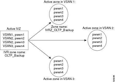
Figure 16-3 depicts an IVR zone consisting of four members. To allow pwwn1 to communicate with pwwn2, they must be in the same zone in VSAN 1, as well as in VSAN 2. If they are not in the same zone, then the hard-zoning ACL entries will prohibit pwwn1 from communicating with pwwn2.

A zone corresponding to each active IVR zone is automatically created in each edge VSAN specified in the active IVR zone. All pWWNs in the IVR zone are members of these zones in each VSAN.

Figure 16-3 Creating Zones upon IVR Zone Activation

The zones are created automatically by the IVR process when an IVR zone set is activated. They are not stored in a full zone set database and are lost when the switch reboots or when a new zone set is activated. The IVR feature monitors these events and adds the zones corresponding to the active IVR zone set configuration when a new zone set is activated. Like zone sets, IVR zone sets are also activated nondisruptively.


Note If pwwn1 and pwwn2 are in an IVR zone in the current as well as the new IVR zone set , then activation of the new IVR zone set does not cause any traffic disruption between them.


IVR zone and IVR zone set names are restricted to 64 alphanumeric characters.

Configuring IVR Zones and Zone Sets

To create IVR zones or zone sets using Fabric Manager, follow these steps:


Step 1 Select the VSAN that you want to configure from the Logical Domains tree.

Step 2 Choose Zone > IVR > Edit Local Full Zone Database from the Zone menu.

You see the Edit IVR Local Full Zone Database dialog box for the VSAN you selected.

Step 3 Right- click the zone set or zone for that VSAN and select Insert to add a zone set or zone.

If you are adding a zone set, you can activate it by right-clicking the newly created zone set and selecting Activate. This configuration is distributed to the other switches in the network fabric.


Note When you confirm the activate operation, the current running configuration is saved to the startup configuration. This permanently saves any changes made to the running configuration (not just zoning changes).


Note Sometimes zones beginning with prefix IVRZ and a zone set with name nozoneset appear in logical view. The zones with prefix IVRZ are IVR zones that get appended to regular active zones. The prefix IVRZ is appended to active IVR zones by the system. Similarly the zone set with name nozoneset is an IVR active zone set created by the system if no active zone set is available for that VSAN and if the ivrZonesetActivateForce flag is enabled on the switch. In the server.properties file, you can set the property zone.ignoreIVRZones to true or false to either hide or view IVR zones as part of regular active zones. See the "Fabric Manager Server Properties File" section on page 2-8 for more information on the server.properties file.


Note Do not create a zone with prefix the IVRZ or a zone set with name nozoneset. These names are used by the system for identifying IVR zones.


Step 4 Optionally, check the Permit QoS Traffic with Priority: check box and set the QoS priority for this zone.

Step 5 Click OK to create this zone or zone set or click Close to discard all changes.


Creating Additional IVR Zones and Zone Sets

To create additional zones and zone sets using Fabric Manager, follow these steps:


Step 1 Click Zone > IVR > Edit Local Full Zone Database. You see the Edit Local Full Zone Database dialog box.

Step 2 Right-click the Zones folder and choose Insert from the pop-up menu.

Step 3 Enter the zone name in the dialog box that appears and click OK to add the zone.

The zone is automatically added to the zone database.

Step 4 Right-click the ZoneSets folder in the Edit Local Full Zone Database dialog box, and choose Insert.

Step 5 Enter the zone set name in the dialog box that appears and click OK to add the zone set.

The zone set is automatically added to the zone database.


Activating IVR Zone Sets

Once the zone sets have been created and populated, you must activate the zone set.

To activate an IVR zone set, follow these steps:


Step 1 Click Zone > IVR > Edit Local Full Zone Database. You see the Edit Local Full Zone Database dialog box.

Step 2 Right-click the Zoneset folder and choose the zone set that you want to activate from the pop-up menu.

Step 3 Click Activate.


Note The active zone set in Edit Zone is shown in bold if any change has been made to the full zoneset resulting in a difference between the active zoneset and full zoneset. Activating the zoneset, unbolds it.


Deactivating IVR Zone Sets

To activate a zone set, follow these steps:


Step 1 Click Zone > IVR > Edit Local Full Zone Database. You see the Edit Local Full Zone Database dialog box.

Step 2 Right-click the Zoneset folder and choose the zone set that you want to activate from the pop-up menu.

Step 3 Click Deactivate.


Recovering an IVR Full Zone Database

You can recover an IVR zone database by copying the IVR full zone database.

To recover an IVR zone database, follow these steps:


Step 1 From Fabric Manager, choose Zone > IVR > Copy Full Zone Database from the Zone menu. You see the Copy Full Zone Database dialog box.

Step 2 Select the Active or the Full radio button, depending on which type of IVR database you want to copy.

Step 3 Select the source switch from which to copy the information from the drop-down list.

Step 4 Select the destination switch from the drop-down list.

Step 5 Click Copy to copy the database, or click Close to close the dialog box without copying.


Recovering an IVR Full Topology

You can recover a topology by copying from the active zone database or the full zone database.

To recover a zone topology, follow these steps.


Step 1 From Fabric Manager, choose Zone > IVR > Copy Full Topology. You see the Copy Full Topology dialog box.

Step 2 Select the Active or the Full radio button, depending on which type of IVR database you want to copy from.

Step 3 Select the source switch from which to copy the information from the drop-down list.

Step 4 Select the destination switch from the drop-down list.

Step 5 Click Copy to copy the topology, or click Close to close the dialog box without copying.


Adding Members to IVR Zones

You can add members to existing IVR zones using the Edit Local Full Zone Database dialog box. LUN-zoning can optionally be used between members of active IVR zones.

To add members to an existing IVR zone and optionally configure LUN zoning using Fabric Manager, follow these steps:


Step 1 Click Zone > IVR > Edit Local Full Zone Database . You see the Edit Local Full Zone Database dialog box.

Step 2 Expand the Zones folder and choose the zone you want to add a member to.

Step 3 Click the Insert icon to add a new member in this zone. You see the zone membership dialog box.

Step 4 Set the WWN for the end device you want to add as a member of this IVR zone.

Step 5 Set the Port VSAN Id and Fabric ID for this end device.

Step 6 Optionally, check the LUNs check box and set the LUNs you want this IVR zone to access on this end device.

Step 7 Click Add to add the member to the IVR zone with the optional LUN zoning attribute or click Close to discard all changes.


IVR Interoperability

When using the IVR feature, all border switches in a given fabric must be Cisco MDS switches. However, other switches in the fabric may be non-MDS switches. For example, end devices that are members of the active IVR zone set may be connected to non-MDS switches. Non-MDS switches may also be present in the transit VSAN(s) or in the edge (VSANs) if one of the interop modes is enabled.