Set Up Access Point Auto Location

Access Point Auto Location

The Access Point Auto Location solution helps to effectively self-locate APs in a global coordinate by combining various ranging technologies and algorithms.

This solution delivers accurate, automated, up-to-date AP location leveraging Fine Timing Measurement (FTM) and Global Navigation Satellite System (GNSS) when available. If GNSS is not accessible, you must place a few manual anchors per each floor. This feature requires an AP density such that neighboring APs can hear each other at maximum power. The accuracy of the Access Point Auto Location feature depends on the building type and the distances between APs.

The configurations required for APs to enable the ranging orchestration are achieved using the Access Point Auto Location feature in Cisco Catalyst 9800 Series Wireless Controllers. For more information, see "Information About Access Point Auto Location Support" in the Cisco Catalyst 9800 Series Wireless Controller Software Configuration Guide.

In Cisco Spaces, to support the AP Auto Location solution, a new feature Device Placement is available under Menu () > Setup > Device Placement.

Figure 1. Device Placement

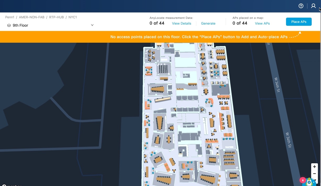
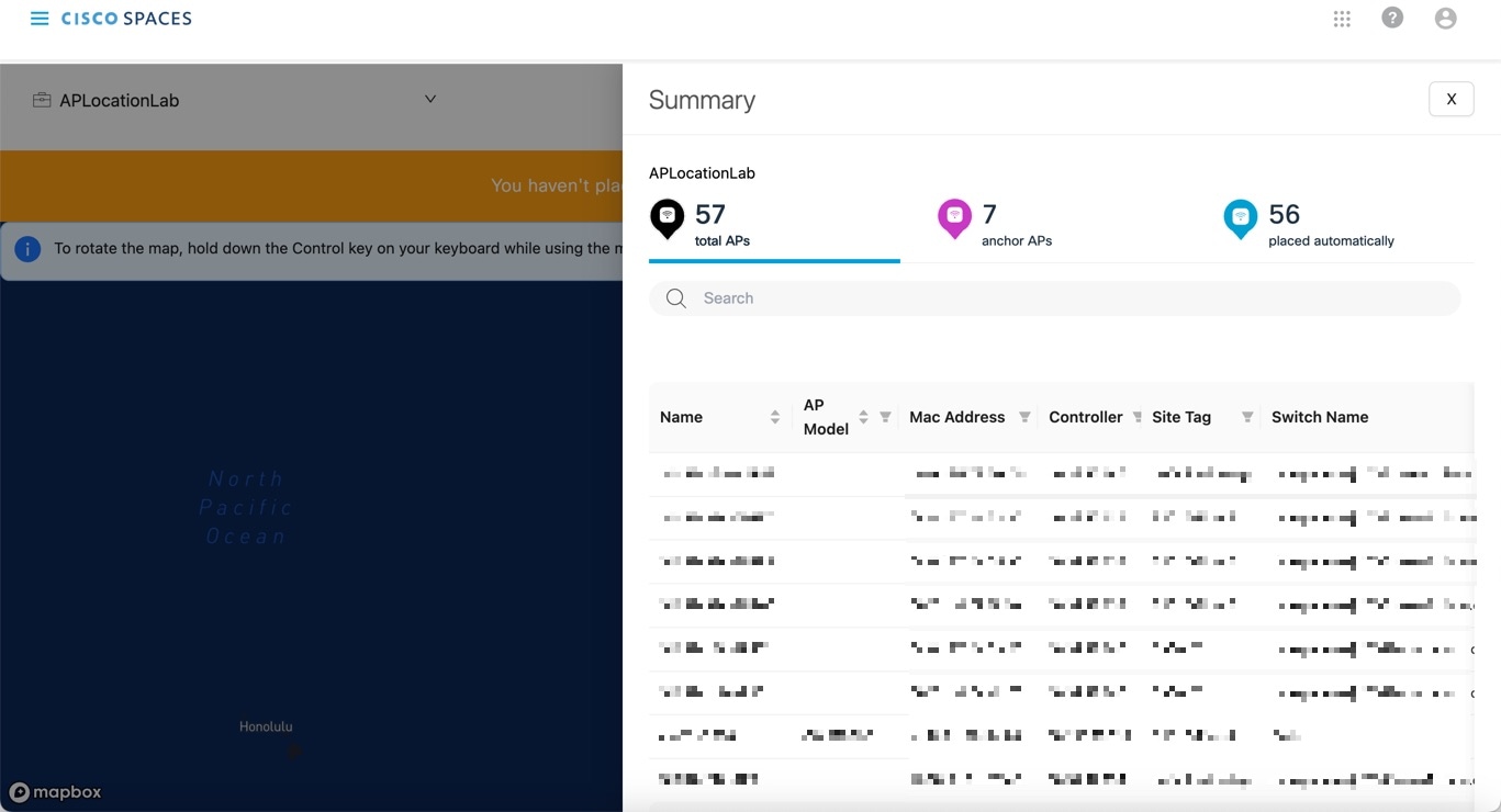
The AP Auto Location solution automatically locates your APs on a digital map in Cisco Spaces. After an administrator anchors several APs with known locations on the floor plan, this feature helps to determine the position of the remaining APs and automatically places them on the Rich Map. If APs have Global Positioning System (GPS) capabilities, the anchors may be automatically positioned on the map.

Restrictions for Access Point Auto Location

The feature is not supported on the default-site-tag.

Supported Platforms

The AP Auto Location feature is supported on the following platforms and versions:

Table 1. Supported Platforms and Versions
Product Platform Releases

Cisco Catalyst 9100 Family of Access Points

  • Cisco Catalyst 9130 Series Access Points

  • Cisco Catalyst 9136 Series Access Points

  • Cisco Catalyst 9164 Series Access Points

  • Cisco Catalyst 9166 Series Access Points

Minimum required version is Cisco IOS XE 17.12.1

Cisco Catalyst 9800 Series Wireless Controllers

Cisco Catalyst 9800 Series Wireless Controllers

Cisco IOS XE 17.12.x

Cisco Spaces

Cisco Spaces: Connector 3

Location Service 3.1.0.94 or later


Note


Along with the supported platforms, ensure that you also have a Cisco Spaces Cloud account.


Prerequisites for AP Auto Location

To successfully place the devices, ensure that the following prerequisites are met:

  • Cisco Catalyst 9800 Series Wireless Controllers must be connected to the Cisco Spaces: Connector and both must be available in the Cisco Spaces cloud account. For more information, see "Connect Connector to Cisco Catalyst 9800 Series Wireless Controllers" in the Cisco Spaces: Connector 3 Configuration Guide.

  • Rich maps must be available for the floors to place the AP. Use the Locations & Maps feature to add rich maps. For more information, see Setting up Locations and Maps.

  • Site tags are mandatory for the floors. Use the Cisco Catalyst 9800 Series Wireless Controllers GUI to create site tags. The APs that you are placing in Cisco Spaces must be associated with the site tags. For more information about configuring site tags, see "Configuring a Site Tag" in the Cisco Catalyst 9800 Series Wireless Controller Software Configuration Guide.

  • Generate Fine Time Measurement (FTM) ranging data for APs. Click View Details to verify the ranging data availability and Generate AP to AP Ranging Data.

Generate AnyLocate Measurement Data

Before starting the AP Auto Location process, you must generate the AnyLocate Measurement data for the APs to automatically place the APs in Cisco Spaces. The ranging measurement process changes the AP channel in the selected area to a common channel and uses FTM to determine the distance between the APs. You need to run this process once, or when APs are moved or added to another environment.

Use Cisco Spaces to generate Fine Time Measurement (FTM) ranging data for APs to place them on the floor map. FTM ranging data is more resilient than RSSI and has better accuracy. Select a site tag and generate the ranging data for all APs associated with that site tag.

Before you begin

Use the Cisco Catalyst 9800 Series Wireless Controller GUI to achieve the following:


Note


  • The AnyLocate Measurement Data process is not supported for a default site tag.

  • We recommend that you schedule the ranging process when the network is less busy as this process is disruptive. This process takes approximately 10 minutes to complete.

  • The AnyLocate Measurement ranging process can be triggered per site tag basis and is not supported for a default site tag.


Procedure


Step 1

Log in to Cisco Spaces.

Step 2

In the Cisco Spaces dashboard, click the Menu icon () and choose Setup > Device Placement.

Step 3

In the Device Placement window, click Generate.

In a Day 0 configuration scenario, there is no AP ranging data available and you must click the Generate option displayed on the GUI to initiate the AP ranging data generation process. The Generate AnyLocate measurement Data window displays the site tags, number of ranging capable APs, controller, and AP model information.
Figure 2. Generate AnyLocate Measurement Data

Step 4

Select the site tags in the Site Tag column for which you want to generate the AnyLocate Measurement data.

The selected site tags and the corresponding controller details are displayed in the right side of the window. You can also check the Site Tag check box to select all site tags.

Note

 
Generating ranging data for default site tags is not supported in Cisco Spaces.

Step 5

Click Next.

Step 6

Choose the scheduling option to generate AnyLocate Measurement data. The following options are available:

  • Schedule it for later: Select this option to specify a date and time to generate AnyLocate Measurement data.

  • Generate Now: Select this option to proceed with generating AnyLocate Measurement data.

Step 7

Click Generate.


Place Devices

Use the Device Placement feature to place the APs on the floor maps. Cisco Spaces uses various ranging technologies and algorithms to place the APs as per the global geographic coordinates. A site tag must be configured for each floor to place the APs successfully on the map.

Procedure


Step 1

Log in to Cisco Spaces.

Step 2

In the Cisco Spaces dashboard, click the Menu icon () and choose Setup > Device Placement.

Step 3

In the Device Placement window, from the Floor drop-down list, select the floor where you need to place the devices.

  • Rich Maps are mandatory to place the APs. If rich maps are not available for a location, you cannot place the APs.

  • Check the Show Locations without Map check box to filter and display locations without rich maps.

Step 4

In a Day 0 configuration scenario, a message is displayed indicating that no APs are placed on the floor. Click Place APs to place the devices.

The Place APs window is displayed with three sections: Choose APs, Place APs and Review & Publish.

Step 5

In the Choose APs section, check the check box corresponding to the cluster with APs to be placed in the specific floor.

Note

 
  • By default, the Automatically group neighbor APs check box is checked and the APs are automatically grouped. Uncheck this check box to ungroup the APs and view them as a single list.

  • All available AP clusters and the total AP count are displayed.

  • For each cluster, you can view the controller, switch and site tag information.

  • You can select multiple clusters to assign to a floor.

  • APs with default-site-tag is excluded from the AP grouping.

  • The AP grouping feature is available in the Connector May 2023 release. We recommend that you upgrade your Connector to the latest version to enable the AP grouping feature.

  1. (Optional) Click and expand the AP cluster to view the APs available under the group neighbor.

    The right panel displays the selected AP names and count. You can view the following AP information:

    • Name

    • AP Model

    • MAC Address

    • Controller

    • Site Tag

    • Switch Name

    • IP Address

  2. (Optional) To search APs, enter the AP name in the Search field and click Enter.

  3. (Optional) Click Filter to enter the filtering parameters to display the available APs.

Step 6

Click Next.

Step 7

In the Place APs section, you can view the APs getting placed automatically.

Figure 3. Auto-Place APs

When the APs are placed successfully, the following message is displayed: The AP placement is complete for this floor. Please verify AP positions and make adjustments if needed or click “Next” to proceed.

Note

 
  • The APs highlighted in blue color are not suitable as anchors APs.

  • All GPS capable APs are automatically placed on the map based on their reported GPS measurements. Adjust the positions of any APs to establish them as anchors to provide more accurate positions for all APs on the floor.

  • If there are no GPS capable APs, the APs are placed based on the AP to AP relative positioning data.

  1. Select the required AP and adjust the position manually.

    Note


    The APs are color-coded as:

    • Auto-placed APs in blue

    • Manually adjusted APs in light green and dark green

    APs with an additional GPS module attached are in dark green color. Click an AP to view the additional information in the right panel.

  2. If you adjust the placement of 4 APs, a message is displayed to confirm the recalibration. Click Recalibrate to run the algorithm again to auto-place the APs.

    Click Skip to skip this step.

  3. (Optional) To adjust the AP placements, use the controls (available on the top of the Rich map ) to readjust the AP group position if required and click Confirm Position/Proceed.

    You can flip or rotate the whole AP group and adjust the group placement. After you confirm the new placement, the AP group ring is not longer available.

    Figure 4. Place APs Section

Step 8

Click Next.

Step 9

In the Review & Publish section, select an AP.

The Access Point Details slide-in window is displayed.

  1. Edit the default AP height, modify AP specific parameters if required.

    If you set the AP default height, all APs placed on the map inherit the same AP height parameter and the same is shared with the Cisco Spaces: Detect and Locate app.

  2. Click Save.

Step 10

click Publish.

A pop-up message is displayed and click Done. You can view the placed APs in the Cisco Spaces: Detect and Locate app.


Edit Device Placement

Use the Modify AP Placement option to update the placement of APs on the floor. This option is enabled in the Device Placement window only if the selected floor has APs already placed on the floor map.

If there were any changes to the AP positioning, the Device Placement window displays a message and click View to display the APs Notifications slide-in window. You can review the APs that are either removed or moved from one floor to another and take the necessary action.

View the following AP details:

  • AP Name

  • Mac Address

  • Reported Time

  • Details

  • Status

  • Controller IP Address

Procedure


Step 1

Log in to Cisco Spaces.

Step 2

In the Cisco Spaces dashboard, click the Menu icon () and choose Setup > Device Placement.

Step 3

In the Device Placement window, from the Floor drop-down list, select the floor where you need to edit the device placement.

Step 4

Click Modify AP Placement.

Step 5

In the Choose APs area, check or uncheck the check box against the required APs to update them.

The site tag associated with the floor is displayed along with the AP details such as the AP model, MAC address, controller, switch name, and so on.

The selected APs are displayed under the Selected APs section.

Step 6

Click Next.

Step 7

In the Place APs area, you can view the auto-placement of APs.

Cisco Spaces computes the AP location and places them on the floor map. View the rich map with the APs along with the calculated confidence percentage against each computed AP. You can manually adjust the AP placement if the calculated AP is not correctly placed.

Step 8

Click Next.

Step 9

In the Review and Publish area, verify the AP placement accuracy and click Publish.


View AnyLocate Measurement Data Status

AnyLocate Measurement data is required to process AP location. Generating measurement data might disrupt wireless connections for the APs participating in the ranging processes.

Procedure


Step 1

Log in to Cisco Spaces.

Step 2

In the Cisco Spaces dashboard, click the Menu icon () and choose Setup > Device Placement.

Step 3

In the Device Placement window, click View Details.

The AnyLocate Measurement Data Status window is displayed. You can view the following AnyLocate Measurement data status:

  • Ranging data generated for the number of APs and sites

  • Number of APs with no site tags

  • APs that do not support ranging data

  • Number of site tags with a schedule for generating ranging data

Step 4

(Optional) Click Manage / View History to view the history of ranging data generation.

The Ranging Data History window displays both the executed and scheduled history status. Click Cancel to cancel the ranging data generation schedule.

Step 5

In the AP to AP Ranging Data Status window, view the following options:

  • Site Tag: Displays the site tag. Default site tags are not supported for AP ranging data.

  • Ranging Capable APs: Displays the number of APs capable of generating ranging data from the total number of APs placed on the floor. Click the number to view the details in the slide-in window.

  • Controller: Displays the controller.

  • AP Model(s): Displays the AP models.

  • Status: Displays the status of whether ranging data is generated or not. If ranging data is not generated for a site tag, the status is displayed as Not Available. You can click Generate to generate the data and proceed. If ranging data is already generated, the status is displayed as Available. You can click Re-Generate to regenerate the data if required.

  • Last Generated: Displays the time stamp details of ranging data generation.

Figure 5. AnyLocate Measurement Data Status

Step 6

Click the Close () icon to close the window.


View APs

Procedure


Step 1

Log in to Cisco Spaces.

Step 2

In the Cisco Spaces dashboard, click the Menu icon () and choose Setup > Device Placement.

Step 3

In the Device Placement window, from the Floor drop-down list, select the floor to view the placed AP details.

Step 4

Click View APs.

The slide-in window is displayed with the details of the APs placed on the floor.

You can view the following AP to AP ranging data status:

  • Total number of APs

  • Number of anchor APs

  • Number of APs placed automatically

Step 5

View the following AP details:

  • Name

  • AP Model

  • MAC address

  • Controller

  • Site Tag

  • Switch Name

Figure 6. View AP Details

Step 6

Click the Close () icon to close the slide-in window.