-
- MPLS Traffic Engineering - LSP Attributes
- MPLS Traffic Engineering (TE) - Autotunnel Primary and Backup
- MPLS Traffic Engineering - AutoTunnel Mesh Groups
- MPLS Traffic Engineering - Verbatim Path Support
- MPLS Traffic Engineering - RSVP Hello State Timer
- MPLS Traffic Engineering Forwarding Adjacency
- MPLS Traffic Engineering (TE) - Class-based Tunnel Selection
- MPLS Traffic Engineering - Interarea Tunnels
- MPLS TE - Bundled Interface Support
- MPLS Traffic Engineering�Automatic Bandwidth Adjustment for TE Tunnels
- MPLS Point-to-Multipoint Traffic Engineering
- MPLS Traffic Engineering�Tunnel Source
-
- MPLS Traffic Engineering - Inter-AS TE
- MPLS Traffic Engineering - Shared Risk Link Groups
- MPLS Traffic Engineering (TE) - Autotunnel Primary and Backup
- MPLS Traffic Engineering (TE) - Path Protection
- MPLS Traffic Engineering (TE) - Fast Reroute (FRR) Link and Node Protection
- MPLS TE: Link and Node Protection, with RSVP Hellos Support (with Fast Tunnel Interface Down Detection)
- MPLS Traffic Engineering: BFD-triggered Fast Reroute (FRR)
-
- MPLS MTU Command Changes
- AToM Static Pseudowire Provisioning
- MPLS Pseudowire Status Signaling
- L2VPN Interworking
- L2VPN Pseudowire Redundancy
- L2VPN Pseudowire Switching
- VPLS Autodiscovery: BGP Based
- H-VPLS N-PE Redundancy for QinQ and MPLS Access
- L2VPN Multisegment Pseudowires
- QOS Policy Support on L2VPN ATM PVPs
- L2VPN: Pseudowire Preferential Forwarding
-
- Configuring MPLS Layer 3 VPNs
- MPLS VPN Half-Duplex VRF
- MPLS VPN�Show Running VRF
- MPLS VPN�VRF CLI for IPv4 and IPv6 VPNs
- MPLS VPN--BGP Local Convergence
- MPLS VPN�Route Target Rewrite
- MPLS VPN�Per VRF Label
- MPLS VPN 6VPE per VRF Label
- MPLS Multi-VRF (VRF Lite) Support
- BGP Best External
- BGP PIC Edge for IP and MPLS-VPN
- MPLS VPN - L3VPN over GRE
- Dynamic Layer-3 VPNs with Multipoint GRE Tunnels
- MPLS VPN over mGRE
-
- MPLS LSP Ping/Traceroute for LDP/TE, and LSP Ping for VCCV
- MPLS EM�MPLS LSP Multipath Tree Trace
- Pseudowire Emulation Edge-to-Edge MIBs for Ethernet, Frame Relay, and ATM Services
- MPLS Enhancements to Interfaces MIB
- MPLS Label Distribution Protocol MIB Version 8 Upgrade
- MPLS EM�MPLS LDP MIB - RFC 3815
- MPLS Label Switching Router MIB
- MPLS EM�MPLS LSR MIB - RFC 3813
- MPLS Traffic Engineering MIB
- MPLS Traffic Engineering - Fast Reroute MIB
- MPLS EM - TE MIB RFC 3812
- MPLS VPN�MIB Support
- MPLS EM - MPLS VPN MIB RFC4382 Upgrade
-
- MPLS High Availability: Overview
- MPLS High Availability: Command Changes
- MPLS LDP Graceful Restart
- NSF/SSO - MPLS LDP and LDP Graceful Restart
- NSF/SSO: MPLS VPN
- AToM Graceful Restart
- NSF/SSO�Any Transport over MPLS and AToM Graceful Restart
- NSF/SSO - MPLS TE and RSVP Graceful Restart
- ISSU MPLS Clients
- NSF/SSO/ISSU Support for VPLS
- NSF/SSO and ISSU - MPLS VPN 6VPE and 6PE
Cisco IOS Multiprotocol Label Switching Configuration Guide, Release 12.2SR
Bias-Free Language
The documentation set for this product strives to use bias-free language. For the purposes of this documentation set, bias-free is defined as language that does not imply discrimination based on age, disability, gender, racial identity, ethnic identity, sexual orientation, socioeconomic status, and intersectionality. Exceptions may be present in the documentation due to language that is hardcoded in the user interfaces of the product software, language used based on RFP documentation, or language that is used by a referenced third-party product. Learn more about how Cisco is using Inclusive Language.
- Updated:
- February 12, 2008
Chapter: MPLS VPN Carrier Supporting Carrier with BGP
- Finding Feature Information
- Contents
- Prerequisites for MPLS VPN CSC with BGP
- Restrictions for MPLS VPN CSC with BGP
- Information About MPLS VPN CSC with BGP
MPLS VPN Carrier Supporting Carrier with BGP
Multiprotocol Label Switching (MPLS) Virtual Private Network (VPN) Carrier Supporting Carrier (CSC) enables one MPLS VPN-based service provider to allow other service providers to use a segment of its backbone network. This module explains how to configure an MPLS VPN CSC network that uses Border Gateway Protocol (BGP) to distribute routes and MPLS labels.
Finding Feature Information
Your software release may not support all the features documented in this module. For the latest feature information and caveats, see the release notes for your platform and software release. To find information about the features documented in this module, and to see a list of the releases in which each feature is supported, see the "Feature Information for MPLS VPN CSC with BGP" section.
Use Cisco Feature Navigator to find information about platform support and Cisco IOS and Catalyst OS software image support. To access Cisco Feature Navigator, go to http://www.cisco.com/go/cfn. An account on Cisco.com is not required.
Contents
•![]() Prerequisites for MPLS VPN CSC with BGP
Prerequisites for MPLS VPN CSC with BGP
•![]() Restrictions for MPLS VPN CSC with BGP
Restrictions for MPLS VPN CSC with BGP
•![]() Information About MPLS VPN CSC with BGP
Information About MPLS VPN CSC with BGP
•![]() How to Configure MPLS VPN CSC with BGP
How to Configure MPLS VPN CSC with BGP
•![]() Configuration Examples for MPLS VPN CSC with BGP
Configuration Examples for MPLS VPN CSC with BGP
•![]() Feature Information for MPLS VPN CSC with BGP
Feature Information for MPLS VPN CSC with BGP
Prerequisites for MPLS VPN CSC with BGP
•![]() You should be able to configure MPLS VPNs with end-to-end (CE-to-CE router) pings working. To accomplish this, you need to know how to configure Interior Gateway Protocols (IGPs), MPLS Label Distribution Protocol (LDP), and Multiprotocol Border Gateway Protocol (MP-BGP).
You should be able to configure MPLS VPNs with end-to-end (CE-to-CE router) pings working. To accomplish this, you need to know how to configure Interior Gateway Protocols (IGPs), MPLS Label Distribution Protocol (LDP), and Multiprotocol Border Gateway Protocol (MP-BGP).
•![]() Make sure that the CSC-PE routers and the CSC-CE routers run images that support BGP label distribution. Otherwise, you cannot run external BGP (EBGP) between them. Ensure that connectivity between the customer carrier and the backbone carrier. EBGP-based label distribution is configured on these links to enable MPLS between the customer and backbone carriers.
Make sure that the CSC-PE routers and the CSC-CE routers run images that support BGP label distribution. Otherwise, you cannot run external BGP (EBGP) between them. Ensure that connectivity between the customer carrier and the backbone carrier. EBGP-based label distribution is configured on these links to enable MPLS between the customer and backbone carriers.
Restrictions for MPLS VPN CSC with BGP
On a provider edge (PE) router, you can configure an interface for either BGP with labels or LDP. You cannot enable both types of label distribution on the same interface. If you switch from one protocol to the other, then you must disable the existing protocol on all interfaces before enabling the other protocol.
This feature does not support the following:
•![]() EBGP multihop between CSC-PE and CSC-CE routers
EBGP multihop between CSC-PE and CSC-CE routers
•![]() EIBGP multipath load sharing
EIBGP multipath load sharing
The physical interfaces that connect the BGP speakers must support Cisco Express Forwarding or distributed Cisco Express Forwarding and MPLS.
Information About MPLS VPN CSC with BGP
Before configuring MPLS VPN CSC, you should understand the following concepts:
•![]() Benefits of Implementing MPLS VPN CSC
Benefits of Implementing MPLS VPN CSC
•![]() Benefits of Implementing MPLS VPN CSC with BGP
Benefits of Implementing MPLS VPN CSC with BGP
•![]() Configuration Options for MPLS VPN CSC with BGP
Configuration Options for MPLS VPN CSC with BGP
MPLS VPN CSC Introduction
Carrier supporting carrier is where one service provider allows another service provider to use a segment of its backbone network. The service provider that provides the segment of the backbone network to the other provider is called the backbone carrier. The service provider that uses the segment of the backbone network is called the customer carrier.
A backbone carrier offers Border Gateway Protocol and Multiprotocol Label Switching (BGP/MPLS) VPN services. The customer carrier can be either:
•![]() An Internet service provider (ISP)
An Internet service provider (ISP)
•![]() A BGP/MPLS VPN service provider
A BGP/MPLS VPN service provider
Benefits of Implementing MPLS VPN CSC
The MPLS VPN CSC network provides the following benefits to service providers who are backbone carriers and to customer carriers.
Benefits to the Backbone Carrier
•![]() The backbone carrier can accommodate many customer carriers and give them access to its backbone. The backbone carrier does not need to create and maintain separate backbones for its customer carriers. Using one backbone network to support multiple customer carriers simplifies the backbone carrier's VPN operations. The backbone carrier uses a consistent method for managing and maintaining the backbone network. This is also cheaper and more efficient than maintaining separate backbones.
The backbone carrier can accommodate many customer carriers and give them access to its backbone. The backbone carrier does not need to create and maintain separate backbones for its customer carriers. Using one backbone network to support multiple customer carriers simplifies the backbone carrier's VPN operations. The backbone carrier uses a consistent method for managing and maintaining the backbone network. This is also cheaper and more efficient than maintaining separate backbones.
•![]() The MPLS VPN carrier supporting carrier feature is scalable. Carrier supporting carrier can change the VPN to meet changing bandwidth and connectivity needs. The feature can accommodate unplanned growth and changes. The carrier supporting carrier feature enables tens of thousands of VPNs to be set up over the same network, and it allows a service provider to offer both VPN and Internet services.
The MPLS VPN carrier supporting carrier feature is scalable. Carrier supporting carrier can change the VPN to meet changing bandwidth and connectivity needs. The feature can accommodate unplanned growth and changes. The carrier supporting carrier feature enables tens of thousands of VPNs to be set up over the same network, and it allows a service provider to offer both VPN and Internet services.
•![]() The MPLS VPN carrier supporting carrier feature is a flexible solution. The backbone carrier can accommodate many types of customer carriers. The backbone carrier can accept customer carriers who are ISPs or VPN service providers or both. The backbone carrier can accommodate customer carriers that require security and various bandwidths.
The MPLS VPN carrier supporting carrier feature is a flexible solution. The backbone carrier can accommodate many types of customer carriers. The backbone carrier can accept customer carriers who are ISPs or VPN service providers or both. The backbone carrier can accommodate customer carriers that require security and various bandwidths.
Benefits to the Customer Carriers
•![]() The MPLS VPN carrier supporting carrier feature removes from the customer carrier the burden of configuring, operating, and maintaining its own backbone. The customer carrier uses the backbone network of a backbone carrier, but the backbone carrier is responsible for network maintenance and operation.
The MPLS VPN carrier supporting carrier feature removes from the customer carrier the burden of configuring, operating, and maintaining its own backbone. The customer carrier uses the backbone network of a backbone carrier, but the backbone carrier is responsible for network maintenance and operation.
•![]() Customer carriers who use the VPN services provided by the backbone carrier receive the same level of security that Frame Relay or ATM-based VPNs provide. Customer carriers can also use IPSec in their VPNs for a higher level of security; it is completely transparent to the backbone carrier.
Customer carriers who use the VPN services provided by the backbone carrier receive the same level of security that Frame Relay or ATM-based VPNs provide. Customer carriers can also use IPSec in their VPNs for a higher level of security; it is completely transparent to the backbone carrier.
•![]() Customer carriers can use any link layer technology (SONET, DSL, Frame Relay, and so on) to connect the CE routers to the PE routers and the PE routers to the P routers. The MPLS VPN carrier supporting carrier feature is link layer independent. The CE routers and PE routers use IP to communicate, and the backbone carrier uses MPLS.
Customer carriers can use any link layer technology (SONET, DSL, Frame Relay, and so on) to connect the CE routers to the PE routers and the PE routers to the P routers. The MPLS VPN carrier supporting carrier feature is link layer independent. The CE routers and PE routers use IP to communicate, and the backbone carrier uses MPLS.
•![]() The customer carrier can use any addressing scheme and still be supported by a backbone carrier. The customer address space and routing information are independent of the address space and routing information of other customer carriers or the backbone provider.
The customer carrier can use any addressing scheme and still be supported by a backbone carrier. The customer address space and routing information are independent of the address space and routing information of other customer carriers or the backbone provider.
Benefits of Implementing MPLS VPN CSC with BGP
You can configure your CSC network to enable BGP to transport routes and MPLS labels between the backbone carrier PE routers and the customer carrier CE routers using multiple paths. The benefits of using BGP to distribute IPv4 routes and MPLS label routes are:
•![]() BGP takes the place of an IGP and LDP in a VPN forwarding/routing instance (VRF) table. You can use BGP to distribute routes and MPLS labels. Using a single protocol instead of two simplifies the configuration and troubleshooting.
BGP takes the place of an IGP and LDP in a VPN forwarding/routing instance (VRF) table. You can use BGP to distribute routes and MPLS labels. Using a single protocol instead of two simplifies the configuration and troubleshooting.
•![]() BGP is the preferred routing protocol for connecting two ISPs, mainly because of its routing policies and ability to scale. ISPs commonly use BGP between two providers. This feature enables those ISPs to use BGP.
BGP is the preferred routing protocol for connecting two ISPs, mainly because of its routing policies and ability to scale. ISPs commonly use BGP between two providers. This feature enables those ISPs to use BGP.
Configuration Options for MPLS VPN CSC with BGP
The backbone carrier offers BGP and MPLS VPN services. The customer carrier can be either of the following:
•![]() Customer Carrier Is an ISP with an IP Core
Customer Carrier Is an ISP with an IP Core
•![]() Customer Carrier Is an MPLS Service Provider With or Without VPN Services
Customer Carrier Is an MPLS Service Provider With or Without VPN Services
The following sections explain how the backbone and customer carriers distribute IPv4 routes and MPLS labels.
Customer Carrier Is an ISP with an IP Core
Figure 1 shows a network configuration where the customer carrier is an ISP. The customer carrier has two sites, each of which is a point of presence (POP). The customer carrier connects these sites using a VPN service provided by the backbone carrier. The backbone carrier uses MPLS. The ISP sites use IP.
Figure 1 Network Where the Customer Carrier Is an ISP
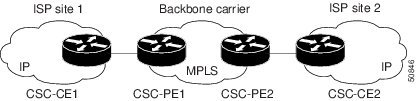
The links between the CE and PE routers use EBGP to distribute IPv4 routes and MPLS labels. Between the links, the PE routers use multiprotocol IBGP to distribute VPNv4 routes.

Note ![]() If a router other than a Cisco router is used as a CSC-PE or CSC-CE, that router must support IPv4 BGP label distribution (RFC 3107). Otherwise, you cannot run EBGP with labels between the routers.
If a router other than a Cisco router is used as a CSC-PE or CSC-CE, that router must support IPv4 BGP label distribution (RFC 3107). Otherwise, you cannot run EBGP with labels between the routers.
Customer Carrier Is an MPLS Service Provider With or Without VPN Services
Figure 2 shows a network configuration where the backbone carrier and the customer carrier are BGP/MPLS VPN service providers. This is known as hierarchical VPNs. The customer carrier has two sites. Both the backbone carrier and the customer carrier use MPLS in their networks.
Figure 2 Network Where the Customer Carrier Is an MPLS VPN Service Provider
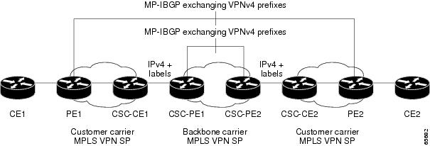
In this configuration, the customer carrier can configure its network in one of the following ways:
•![]() The customer carrier can run IGP and LDP in its core network. In this case, the CSC-CE1 router in the customer carrier redistributes the EBGP routes it learns from the CSC-PE1 router of the backbone carrier to IGP.
The customer carrier can run IGP and LDP in its core network. In this case, the CSC-CE1 router in the customer carrier redistributes the EBGP routes it learns from the CSC-PE1 router of the backbone carrier to IGP.
•![]() The CSC-CE1 router of the customer carrier system can run an IPv4 and labels IBGP session with the PE1 router.
The CSC-CE1 router of the customer carrier system can run an IPv4 and labels IBGP session with the PE1 router.
How to Configure MPLS VPN CSC with BGP
This section contains the following tasks:
•![]() Identifying the Carrier Supporting Carrier Topology (required)
Identifying the Carrier Supporting Carrier Topology (required)
•![]() Configuring the Backbone Carrier Core (required)
Configuring the Backbone Carrier Core (required)
•![]() Configuring the CSC-PE and CSC-CE Routers (required)
Configuring the CSC-PE and CSC-CE Routers (required)
•![]() Configuring the Customer Carrier Network (required)
Configuring the Customer Carrier Network (required)
•![]() Configuring the Customer Site for Hierarchical VPNs (required)
Configuring the Customer Site for Hierarchical VPNs (required)
Identifying the Carrier Supporting Carrier Topology
Before you configure the MPLS VPN CSC with BGP, you need to identify both the backbone and customer carrier topology.
For hierarchical VPNs, the customer carrier of the MPLS VPN network provides MPLS VPN services to its own customers. In this instance, you need to identify the type of customer carrier as well as the topology of the customer carriers. Hierarchical VPNs require extra configuration steps, which are noted in the configuration sections.
Note ![]() You can connect multiple CSC-CE routers to the same PE, or you can connect a single CSC-CE router to CSC-PEs using more than one interface to provide redundancy and multiple path support in CSC topology.
You can connect multiple CSC-CE routers to the same PE, or you can connect a single CSC-CE router to CSC-PEs using more than one interface to provide redundancy and multiple path support in CSC topology.
Perform this task to identify the carrier supporting carrier topology.
SUMMARY STEPS
1. ![]() Identify the type of customer carrier, ISP or MPLS VPN service provider.
Identify the type of customer carrier, ISP or MPLS VPN service provider.
2. ![]() (For hierarchical VPNs only) Identify the CE routers.
(For hierarchical VPNs only) Identify the CE routers.
3. ![]() (For hierarchical VPNs only) Identify the customer carrier core router configuration.
(For hierarchical VPNs only) Identify the customer carrier core router configuration.
4. ![]() Identify the customer carrier edge (CSC-CE) routers.
Identify the customer carrier edge (CSC-CE) routers.
5. ![]() Identify backbone carrier router configuration.
Identify backbone carrier router configuration.
DETAILED STEPS
What to Do Next
Set up your carrier supporting carrier networks with the "Configuring the Backbone Carrier Core" section.
Configuring the Backbone Carrier Core
Configuring the backbone carrier core requires setting up connectivity and routing functions for the CSC core and the CSC-PE routers.
Configuring and verifying the CSC core (backbone carrier) involves the following tasks:
•![]() Verifying IP Connectivity and LDP Configuration in the CSC Core (optional)
Verifying IP Connectivity and LDP Configuration in the CSC Core (optional)
•![]() Configuring VRFs for CSC-PE Routers (required)
Configuring VRFs for CSC-PE Routers (required)
•![]() Configuring Multiprotocol BGP for VPN Connectivity in the Backbone Carrier (required)
Configuring Multiprotocol BGP for VPN Connectivity in the Backbone Carrier (required)
Prerequisites
Before you configure a backbone carrier core, configure the following on the CSC core routers:
•![]() An IGP routing protocol—BGP, OSPF, IS-IS, EIGRP, static, and so on.
An IGP routing protocol—BGP, OSPF, IS-IS, EIGRP, static, and so on.
•![]() Label Distribution Protocol (LDP). For information, see How to Configure MPLS LDP.
Label Distribution Protocol (LDP). For information, see How to Configure MPLS LDP.
Verifying IP Connectivity and LDP Configuration in the CSC Core
Perform this task to verify IP connectivity and LDP configuration in the CSC core.
SUMMARY STEPS
1. ![]() enable
enable
2. ![]() ping [protocol] {host-name | system-address}
ping [protocol] {host-name | system-address}
3. ![]() trace [protocol] [destination]
trace [protocol] [destination]
4. ![]() show mpls forwarding-table [vrf vrf-name] [{network {mask | length} | labels label [- label] | interface interface | next-hop address | lsp-tunnel [tunnel-id]}] [detail]
show mpls forwarding-table [vrf vrf-name] [{network {mask | length} | labels label [- label] | interface interface | next-hop address | lsp-tunnel [tunnel-id]}] [detail]
5. ![]() show mpls ldp discovery [vrf vrf-name | all]
show mpls ldp discovery [vrf vrf-name | all]
6. ![]() show mpls ldp neighbor [[vrf vrf-name] [address | interface] [detail] | all]
show mpls ldp neighbor [[vrf vrf-name] [address | interface] [detail] | all]
7. ![]() show ip cef [vrf vrf-name] [network [mask]] [longer-prefixes] [detail]
show ip cef [vrf vrf-name] [network [mask]] [longer-prefixes] [detail]
8. ![]() show mpls interfaces [[vrf vrf-name] [interface] [detail] | all]
show mpls interfaces [[vrf vrf-name] [interface] [detail] | all]
9. ![]() show ip route
show ip route
10. ![]() disable
disable
DETAILED STEPS
Troubleshooting Tips
You can use the ping and trace commands to verify complete MPLS connectivity in the core. You also get useful troubleshooting information from the additional show commands.
Configuring VRFs for CSC-PE Routers
Perform this task to configure VPN forwarding/routing instances (VRFs) for the backbone carrier edge (CSC-PE) routers.
SUMMARY STEPS
1. ![]() enable
enable
2. ![]() configure terminal
configure terminal
3. ![]() ip vrf vrf-name
ip vrf vrf-name
4. ![]() rd route-distinguisher
rd route-distinguisher
5. ![]() route-target {import | export | both} route-target-ext-community
route-target {import | export | both} route-target-ext-community
6. ![]() import map route-map
import map route-map
7. ![]() exit
exit
8. ![]() interface type number
interface type number
9. ![]() ip vrf forwarding vrf-name
ip vrf forwarding vrf-name
10. ![]() end
end
DETAILED STEPS
Troubleshooting Tips
Enter a show ip vrf detail command and make sure the MPLS VPN is up and associated with the right interfaces.
Configuring Multiprotocol BGP for VPN Connectivity in the Backbone Carrier
Perform this task to configure Multiprotocol BGP (MP-BGP) connectivity in the backbone carrier.
SUMMARY STEPS
1. ![]() enable
enable
2. ![]() configure terminal
configure terminal
3. ![]() router bgp as-number
router bgp as-number
4. ![]() no bgp default ipv4-unicast
no bgp default ipv4-unicast
5. ![]() neighbor {ip-address | peer-group-name} remote-as as-number
neighbor {ip-address | peer-group-name}
remote-as as-number
6. ![]() neighbor {ip-address | peer-group-name} update-source interface-type
neighbor {ip-address | peer-group-name} update-source interface-type
7. ![]() address-family vpnv4 [unicast]
address-family vpnv4 [unicast]
8. ![]() neighbor {ip-address | peer-group-name} send-community extended
neighbor {ip-address | peer-group-name} send-community extended
9. ![]() neighbor {ip-address | peer-group-name} activate
neighbor {ip-address | peer-group-name}
activate
10. ![]() end
end
DETAILED STEPS
Troubleshooting Tips
You can enter a show ip bgp neighbor command to verify that the neighbors are up and running. If this command is not successful, enter a debug ip bgp x.x.x.x events command, where x.x.x.x is the IP address of the neighbor.
Configuring the CSC-PE and CSC-CE Routers
Perform the following tasks to configure and verify links between a CSC-PE router and the carrier CSC-CE router for an MPLS VPN CSC network that uses BGP to distribute routes and MPLS labels.
•![]() Configuring CSC-PE Routers (required)
Configuring CSC-PE Routers (required)
•![]() Configuring CSC-CE Routers (required)
Configuring CSC-CE Routers (required)
•![]() Verifying Labels in the CSC-PE Routers (optional)
Verifying Labels in the CSC-PE Routers (optional)
•![]() Verifying Labels in the CSC-CE Routers (optional)
Verifying Labels in the CSC-CE Routers (optional)
Figure 3 shows the configuration for the peering with directly connected interfaces between CSC-PE and CSC-CE routers. This configuration is used as the example in the tasks that follow.
Figure 3 Configuration for Peering with Directly Connected Interfaces Between CSC-PE and CSC-CE Routers

Configuring CSC-PE Routers
Perform this task to configure the CSC-PE routers.
SUMMARY STEPS
1. ![]() enable
enable
2. ![]() configure terminal
configure terminal
3. ![]() router bgp as-number
router bgp as-number
4. ![]() address-family ipv4 [multicast | unicast | vrf vrf-name]
address-family ipv4 [multicast | unicast | vrf vrf-name]
5. ![]() neighbor {ip-address | peer-group-name} remote-as as-number
neighbor {ip-address | peer-group-name} remote-as as-number
6. ![]() neighbor {ip-address | peer-group-name} activate
neighbor {ip-address | peer-group-name} activate
7. ![]() neighbor ip-address as-override
neighbor ip-address as-override
8. ![]() neighbor ip-address send-label
neighbor ip-address send-label
9. ![]() exit-address-family
exit-address-family
10. ![]() end
end
DETAILED STEPS
Troubleshooting Tips
Enter a show ip bgp neighbor command to verify that the neighbors are up and running. Make sure you see the following line in the command output under Neighbor capabilities:
IPv4 MPLS Label capability:advertised and received
Configuring CSC-CE Routers
Perform this task to configure the CSC-CE routers.
SUMMARY STEPS
1. ![]() enable
enable
2. ![]() configure terminal
configure terminal
3. ![]() router bgp as-number
router bgp as-number
4. ![]() address-family ipv4 [multicast | unicast | vrf vrf-name]
address-family ipv4 [multicast | unicast | vrf vrf-name]
5. ![]() redistribute protocol
redistribute protocol
6. ![]() neighbor {ip-address | peer-group-name} remote-as as-number
neighbor {ip-address | peer-group-name} remote-as as-number
7. ![]() neighbor {ip-address | peer-group-name} activate
neighbor {ip-address | peer-group-name} activate
8. ![]() neighbor
neighbor ip-address send-label
9. ![]() exit-address-family
exit-address-family
10. ![]() end
end
DETAILED STEPS
Verifying Labels in the CSC-PE Routers
Perform this task to verify the labels in the CSC-PE routers.
SUMMARY STEPS
1. ![]() enable
enable
2. ![]() show ip bgp vpnv4 {all | rd route-distinguisher | vrf vrf-name} [summary] [labels]
show ip bgp vpnv4 {all | rd route-distinguisher | vrf vrf-name} [summary] [labels]
3. ![]() show mpls interfaces [all]
show mpls interfaces [all]
4. ![]() show ip route vrf vrf-name [prefix]
show ip route vrf vrf-name [prefix]
5. ![]() show ip bgp vpnv4 {all | rd route-distinguisher | vrf vrf-name} [summary] [labels]
show ip bgp vpnv4 {all | rd route-distinguisher | vrf vrf-name} [summary] [labels]
6. ![]() show ip cef [vrf vrf-name] [network [mask]] [longer-prefixes] [detail]
show ip cef [vrf vrf-name] [network [mask]] [longer-prefixes] [detail]
7. ![]() show mpls forwarding-table [vrf vrf-name] [{network {mask | length} | labels label [- label] | interface interface | next-hop address | lsp-tunnel [tunnel-id]}] [detail]
show mpls forwarding-table [vrf vrf-name] [{network {mask | length} | labels label [- label] | interface interface | next-hop address | lsp-tunnel [tunnel-id]}] [detail]
8. ![]() traceroute vrf [vrf-name] ip-address
traceroute vrf [vrf-name] ip-address
9. ![]() disable
disable
DETAILED STEPS
Verifying Labels in the CSC-CE Routers
Perform this task to verify the labels in the CSC-CE routers.
SUMMARY STEPS
1. ![]() enable
enable
2. ![]() show ip bgp summary
show ip bgp summary
3. ![]() show ip route [address]
show ip route [address]
4. ![]() show mpls ldp bindings [network {mask | length}]
show mpls ldp bindings [network {mask | length}]
5. ![]() show ip cef [network [mask]] [longer-prefixes] [detail]
show ip cef [network [mask]] [longer-prefixes] [detail]
6. ![]() show mpls forwarding-table [vrf vrf-name] [{network {mask | length} | labels label [- label] | interface interface | next-hop address | lsp-tunnel [tunnel-id]}] [detail]
show mpls forwarding-table [vrf vrf-name] [{network {mask | length} | labels label [- label] | interface interface | next-hop address | lsp-tunnel [tunnel-id]}] [detail]
7. ![]() show ip bgp labels
show ip bgp labels
DETAILED STEPS
Configuring the Customer Carrier Network
Perform the following tasks to configure and verify the customer carrier network. This requires setting up connectivity and routing functions for the customer carrier core (P) routers and the customer carrier edge (PE) routers.
•![]() Verifying IP Connectivity in the Customer Carrier (optional)
Verifying IP Connectivity in the Customer Carrier (optional)
•![]() Configuring a Customer Carrier Core Router as a Route Reflector (optional)
Configuring a Customer Carrier Core Router as a Route Reflector (optional)
Prerequisites
Before you configure an MPLS VPN CSC network that uses BGP to distribute routes and MPLS labels, you must configure the following on your customer carrier routers:
•![]() An IGP routing protocol—BGP, OSPF, IS-IS, EIGRP, static, and so on. For information, see Configuring a Basic BGP Network, Configuring OSPF, Configuring a Basic IS-IS Network, and Configuring EIGRP.
An IGP routing protocol—BGP, OSPF, IS-IS, EIGRP, static, and so on. For information, see Configuring a Basic BGP Network, Configuring OSPF, Configuring a Basic IS-IS Network, and Configuring EIGRP.
•![]() MPLS VPN functionality on the PE routers (for hierarchical VPNs only).
MPLS VPN functionality on the PE routers (for hierarchical VPNs only).
•![]() Label Distribution Protocol (LDP) on P and PE routers (for hierarchical VPNs only). For information, see How to Configure MPLS LDP.
Label Distribution Protocol (LDP) on P and PE routers (for hierarchical VPNs only). For information, see How to Configure MPLS LDP.
Note ![]() You must configure the items in the preceding list before performing the tasks in this section.
You must configure the items in the preceding list before performing the tasks in this section.
Verifying IP Connectivity in the Customer Carrier
Perform this task to verify IP connectivity in the customer carrier.
SUMMARY STEPS
1. ![]() enable
enable
2. ![]() ping [protocol] {host-name | system-address}
ping [protocol] {host-name | system-address}
3. ![]() trace [protocol] [destination]
trace [protocol] [destination]
4. ![]() show ip route
show ip route
5. ![]() disable
disable
DETAILED STEPS
Configuring a Customer Carrier Core Router as a Route Reflector
Perform this task to configure a customer carrier core (P) router as a route reflector of multiprotocol BGP prefixes.
SUMMARY STEPS
1. ![]() enable
enable
2. ![]() configure terminal
configure terminal
3. ![]() router bgp as-number
router bgp as-number
4. ![]() neighbor {ip-address | peer-group-name} remote-as as-number
neighbor {ip-address | peer-group-name} remote-as as-number
5. ![]() address-family vpnv4 [unicast]
address-family vpnv4 [unicast]
6. ![]() neighbor {ip-address | peer-group-name} activate
neighbor {ip-address | peer-group-name} activate
7. ![]() neighbor ip-address route-reflector-client
neighbor ip-address route-reflector-client
8. ![]() exit-address-family
exit-address-family
9. ![]() end
end
DETAILED STEPS
Troubleshooting Tips
By default, neighbors that are defined using the neighbor remote-as command in router configuration mode exchange only unicast address prefixes. For neighbors to exchange other address prefix types, such as multicast and VPNv4, you must also activate neighbors using the neighbor activate command in address family configuration mode, as shown.
Route reflectors and clients (neighbors or internal BGP peer groups) that are defined in router configuration mode using the neighbor route-reflector-client command reflect unicast address prefixes to and from those clients by default. To cause them to reflect prefixes for other address families, such as multicast, define the reflectors and clients in address family configuration mode, using the neighbor route-reflector-client command, as shown.
Configuring the Customer Site for Hierarchical VPNs
Note ![]() This section applies only to customer carrier networks that use BGP to distribute routes and MPLS labels.
This section applies only to customer carrier networks that use BGP to distribute routes and MPLS labels.
Perform the following tasks to configure and verify the customer site for hierarchical VPNs:
•![]() Defining VPNs on PE Routers for Hierarchical VPNs (required)
Defining VPNs on PE Routers for Hierarchical VPNs (required)
•![]() Configuring BGP Routing Sessions on the PE Routers for Hierarchical VPNs (required)
Configuring BGP Routing Sessions on the PE Routers for Hierarchical VPNs (required)
•![]() Verifying Labels in Each PE Router for Hierarchical VPNs (optional)
Verifying Labels in Each PE Router for Hierarchical VPNs (optional)
•![]() Configuring CE Routers for Hierarchical VPNs (required)
Configuring CE Routers for Hierarchical VPNs (required)
•![]() Verifying IP Connectivity in the Customer Site (optional)
Verifying IP Connectivity in the Customer Site (optional)
Note ![]() This section applies to hierarchical VPNs only.
This section applies to hierarchical VPNs only.
Defining VPNs on PE Routers for Hierarchical VPNs
Perform this task to define VPNs on PE routers.
SUMMARY STEPS
1. ![]() enable
enable
2. ![]() configure terminal
configure terminal
3. ![]() ip vrf vrf-name
ip vrf vrf-name
4. ![]() rd route-distinguisher
rd route-distinguisher
5. ![]() route-target {import | export | both} route-target-ext-community
route-target {import | export | both} route-target-ext-community
6. ![]() import map route-map
import map route-map
7. ![]() ip vrf forwarding vrf-name
ip vrf forwarding vrf-name
8. ![]() exit
exit
DETAILED STEPS
Configuring BGP Routing Sessions on the PE Routers for Hierarchical VPNs
Perform this task to configure BGP routing sessions on the PE routers for PE-to-CE router communication.
SUMMARY STEPS
1. ![]() enable
enable
2. ![]() configure terminal
configure terminal
3. ![]() router bgp as-number
router bgp as-number
4. ![]() address-family ipv4 [multicast | unicast | vrf vrf-name]
address-family ipv4 [multicast | unicast | vrf vrf-name]
5. ![]() neighbor {ip address | peer-group-name} remote-as as-number
neighbor {ip address | peer-group-name} remote-as as-number
6. ![]() neighbor {ip-address | peer-group-name} activate
neighbor {ip-address | peer-group-name} activate
7. ![]() end
end
DETAILED STEPS
Verifying Labels in Each PE Router for Hierarchical VPNs
Perform this task to verify labels in each PE router for hierarchical VPNs.
SUMMARY STEPS
1. ![]() enable
enable
2. ![]() show ip route vrf vrf-name [prefix]
show ip route vrf vrf-name [prefix]
3. ![]() show mpls forwarding-table [vrf vrf-name] [prefix] [detail]
show mpls forwarding-table [vrf vrf-name] [prefix] [detail]
4. ![]() show ip cef [network [mask [longer-prefix]]] [detail]
show ip cef [network [mask [longer-prefix]]] [detail]
5. ![]() show ip cef vrf vrf-name [ip-prefix]
show ip cef vrf vrf-name [ip-prefix]
6. ![]() exit
exit
DETAILED STEPS
Configuring CE Routers for Hierarchical VPNs
Perform this task to configure CE routers for hierarchical VPNs. This configuration is the same as that for an MPLS VPN that is not in a hierarchical topology.
SUMMARY STEPS
1. ![]() enable
enable
2. ![]() configure terminal
configure terminal
3. ![]() ip cef [distributed]
ip cef [distributed]
4. ![]() interface type number
interface type number
5. ![]() ip address ip-address mask [secondary]
ip address ip-address mask [secondary]
6. ![]() exit
exit
7. ![]() router bgp as-number
router bgp as-number
8. ![]() redistribute protocol
redistribute protocol
9. ![]() neighbor {ip-address | peer-group-name} remote-as as-number
neighbor {ip-address | peer-group-name} remote-as as-number
10. ![]() end
end
DETAILED STEPS
Verifying IP Connectivity in the Customer Site
Perform this task to verify IP connectivity in the customer site.
SUMMARY STEPS
1. ![]() enable
enable
2. ![]() show ip route [ip-address [mask] [longer-prefixes] | protocol [process-id] | list [access-list-number | access-list-name] | static download]
show ip route [ip-address [mask] [longer-prefixes] | protocol [process-id] | list [access-list-number | access-list-name] | static download]
3. ![]() ping [protocol] {host-name | system-address}
ping [protocol] {host-name | system-address}
4. ![]() trace [protocol] [destination]
trace [protocol] [destination]
5. ![]() disable
disable
DETAILED STEPS
Configuration Examples for MPLS VPN CSC with BGP
Configuration examples for the MPLS VPN CSC with BGP include the following:
•![]() Configuring the Backbone Carrier Core: Examples
Configuring the Backbone Carrier Core: Examples
•![]() Configuring the Links Between CSC-PE and CSC-CE Routers: Examples
Configuring the Links Between CSC-PE and CSC-CE Routers: Examples
•![]() Configuring the Customer Carrier Network: Examples
Configuring the Customer Carrier Network: Examples
•![]() Configuring the Customer Site for Hierarchical VPNs: Examples
Configuring the Customer Site for Hierarchical VPNs: Examples
Figure 4 shows a sample CSC topology for exchanging IPv4 routes and MPLS labels. Use this figure as a reference for configuring and verifying carrier supporting carrier routers to exchange IPv4 routes and MPLS labels.
Figure 4 Sample CSC Topology for Exchanging IPv4 Routes and MPLS Labels

Table 1 describes the sample configuration shown in Figure 4.
|
|
|
|---|---|
CE1 and CE2 |
Belong to an end customer. CE1 and CE2 routers exchange routes learned from PE routers. The end customer is purchasing VPN services from a customer carrier. |
PE1 and PE2 |
Part of a customer carrier network that is configured to provide MPLS VPN services. PE1 and PE2 are peering with a VPNv4 IBGP session to form an MPLS VPN network. |
CSC-CE1 and CSC-CE2 |
Part of a customer carrier network. CSC-CE1 and CSC-CE2 routers exchange IPv4 BGP updates with MPLS labels and redistribute PE loopback addressees to and from the IGP (OSPF in this example). The customer carrier is purchasing carrier supporting carrier VPN services from a backbone carrier. |
CSC-PE1 and CSC-PE2 |
Part of the backbone carrier's network configured to provide carrier supporting carrier VPN services. CSC-PE1 and CSC-PE2 are peering with a VPNv4 IP BGP session to form the MPLS VPN network. In the VRF, CSC-PE1 and CSC-PE2 are peering with the CSC-CE routers, which are configured for carrying MPLS labels with the routes, with an IPv4 EBGP session. |
Configuring the Backbone Carrier Core: Examples
Configuration and verification examples for the backbone carrier core included in this section are as follows:
•![]() Verifying IP Connectivity and LDP Configuration in the CSC Core: Example
Verifying IP Connectivity and LDP Configuration in the CSC Core: Example
•![]() Configuring VRFs for CSC-PE Routers: Example
Configuring VRFs for CSC-PE Routers: Example
•![]() Configuring Multiprotocol BGP for VPN Connectivity in the Backbone Carrier: Example
Configuring Multiprotocol BGP for VPN Connectivity in the Backbone Carrier: Example
Verifying IP Connectivity and LDP Configuration in the CSC Core: Example
Check that CSC-PE2 is reachable from CSC-PE1 by entering the following command on CSC-CE1:
Router# ping 10.5.5.5
Type escape sequence to abort.
Sending 5, 100-byte ICMP Echos to 10.5.5.5, timeout is 2 seconds:
!!!!!
Success rate is 100 percent (5/5), round-trip min/avg/max = 4/4/4 ms
Verify the path from CSC-PE1 to CSC-PE2 by entering the following command on CSC-CE1:
Router# trace 10.5.5.5
Type escape sequence to abort.
Tracing the route to 10.5.5.5
1 10.5.5.5 0 msec 0 msec *
Check that CSC-PE router prefixes are in the MPLS forwarding table:
Router# show mpls forwarding-table
Local Outgoing Prefix or Bytes tag Outgoing Next Hop
tag tag or VC Tunnel Id switched interface
16 2/nn dd.dd.dd.dd/32 0 AT2/1/0.1 point2point
17 16 bb.bb.bb.bb/32[V] 30204 Et1/0 pp.0.0.1
21 Pop tag cc.cc.cc.cc/32[V] 0 Et1/0 pp.0.0.1
22 Pop tag nn.0.0.0/8[V] 570 Et1/0 pp.0.0.1
23 Aggregate pp.0.0.0/8[V] 0
2 2/nn gg.gg.gg.gg/32[V] 0 AT3/0.1 point2point
8 2/nn hh.hh.hh.hh/32[V] 15452 AT3/0.1 point2point
29 2/nn qq.0.0.0/8[V] 0 AT3/0.1 point2point
30 2/nn ss.0.0.0/8[V] 0 AT3/0.1 point2point
Check the status of LDP discovery processes in the core:
Router# show mpls ldp discovery
Local LDP Identifier:
ee.ee.ee.ee:0
Discovery Sources:
Interfaces:
ATM2/1/0.1 (ldp): xmit/recv
TDP Id: dd.dd.dd.dd:1
Check the status of LDP sessions in the core:
Router# show mpls ldp neighbor
Peer LDP Ident: dd.dd.dd.dd:1; Local LDP Ident ee.ee.ee.ee:1
TCP connection: dd.dd.dd.dd.646 - ee.ee.ee.ee.11007
State: Oper; Msgs sent/rcvd: 20/21; Downstream on demand
Up time: 00:14:56
LDP discovery sources:
ATM2/1/0.1, Src IP addr: dd.dd.dd.dd
Check the forwarding table (prefixes, next-hops, and interfaces):
Router# show ip cef
Prefix Next Hop Interface
0.0.0.0/0 drop Null0 (default route handler entry)
0.0.0.0/32 receive
dd.dd.dd.dd/32 dd.dd.dd.dd ATM2/1/0.1
ee.ee.ee.ee/32 receive
224.0.0.0/4 drop
224.0.0.0/24 receive
255.255.255.255/32 receive
Note ![]() Also see the "Verifying Labels in the CSC-CE Routers: Examples" section.
Also see the "Verifying Labels in the CSC-CE Routers: Examples" section.
Verify that interfaces are configured to use LDP:
Router# show mpls interfaces
Interface IP Tunnel Operational
Ethernet0/1 Yes (ldp) No Yes
Display the entire routing table, including host IP address, next hop, interface, and so forth:
Router# show ip route
Codes: C - connected, S - static, I - IGRP, R - RIP, M - mobile, B - BGP
D - EIGRP, EX - EIGRP external, O - OSPF, IA - OSPF inter area
N1 - OSPF NSSA external type 1, N2 - OSPF NSSA external type 2
E1 - OSPF external type 1, E2 - OSPF external type 2, E - EGP
i - IS-IS, L1 - IS-IS level-1, L2 - IS-IS level-2, ia - IS-IS inter area
* - candidate default, U - per-user static route, o - ODR
Gateway of last resort is not set
dd.0.0.0/32 is subnetted, 1 subnets
O dd.dd.dd.dd [110/7] via dd.dd.dd.dd, 00:16:42, ATM2/1/0.1
ee.0.0.0/32 is subnetted, 1 subnets
C ee.ee.ee.ee is directly connected, Loopback0
Configuring VRFs for CSC-PE Routers: Example
The following example shows how to configure a VPN routing and forwarding (VRF) instance for a CSC-PE router:
ip cef distributed
ip vrf vpn1
rd 100:1
route target both 100:1
!
Configuring Multiprotocol BGP for VPN Connectivity in the Backbone Carrier: Example
The following example shows how to configure Multiprotocol BGP (MP-BGP) for VPN connectivity in the backbone carrier:
ip cef distributed
ip vrf vpn1
rd 100:1
route target both 100:1
hostname csc-pe1
!
router bgp 100
no bgp default ipv4-unicast
bgp log-neighbor-changes
timers bgp 10 30
neighbor ee.ee.ee.ee remote-as 100
neighbor ee.ee.ee.ee update-source Loopback0
no auto-summary
!
address-family vpnv4
neighbor ee.ee.ee.ee activate
neighbor ee.ee.ee.ee send-community extended
bgp dampening 30
exit-address-family
!
router bgp 100
. . .
! (BGP IPv4 to CSC-CE router from CSC-PE router)
!
address-family ipv4 vrf vpn1
neighbor ss.0.0.2 remote-as 200
neighbor ss.0.0.2 activate
neighbor ss.0.0.2 as-override
neighbor ss.0.0.2 advertisement-interval 5
neighbor ss.0.0.2 send-label
no auto-summary
no synchronization
bgp dampening 30
exit-address-family
!
Configuring the Links Between CSC-PE and CSC-CE Routers: Examples
This section contains the following examples:
•![]() Configuring the CSC-PE Routers: Examples
Configuring the CSC-PE Routers: Examples
•![]() Configuring the CSC-CE Routers: Examples
Configuring the CSC-CE Routers: Examples
•![]() Verifying Labels in the CSC-PE Routers: Examples
Verifying Labels in the CSC-PE Routers: Examples
•![]() Verifying Labels in the CSC-CE Routers: Examples
Verifying Labels in the CSC-CE Routers: Examples
Configuring the CSC-PE Routers: Examples
The following example shows how to configure a CSC-PE router:
ip cef
!
ip vrf vpn1
rd 100:1
route-target export 100:1
route-target import 100:1
mpls label protocol ldp
!
interface Loopback0
ip address dd.dd.dd.dd 255.255.255.255
!
interface Ethernet3/1
ip vrf forwarding vpn1
ip address pp.0.0.2 255.0.0.0
!
interface ATM0/1/0
no ip address
no ip directed-broadcast
no ip route-cache distributed
atm clock INTERNAL
no atm enable-ilmi-trap
no atm ilmi-keepalive
!
interface ATM0/1/0.1 mpls
ip unnumbered Loopback0
no ip directed-broadcast
no atm enable-ilmi-trap
mpls label protocol ldp
mpls atm vpi 2-5
mpls ip
!
router ospf 100
log-adjacency-changes
auto-cost reference-bandwidth 1000
redistribute connected subnets
passive-interface Ethernet3/1
network dd.dd.dd.dd 0.0.0.0 area 100
!
router bgp 100
no bgp default ipv4-unicast
bgp log-neighbor-changes
timers bgp 10 30
neighbor ee.ee.ee.ee remote-as 100
neighbor ee.ee.ee.ee update-source Loopback0
!
address-family vpnv4 !VPNv4 session with CSC-PE2
neighbor ee.ee.ee.ee activate
neighbor ee.ee.ee.ee send-community extended
bgp dampening 30
exit-address-family
!
address-family ipv4 vrf vpn1
neighbor pp.0.0.1 remote-as 200
neighbor pp.0.0.1 activate
neighbor pp.0.0.1 as-override
neighbor pp.0.0.1 advertisement-interval 5
neighbor pp.0.0.1 send-label
no auto-summary
no synchronization
bgp dampening 30
exit-address-family
Configuring the CSC-CE Routers: Examples
The following example shows how to configure a CSC-CE router:
ip cef
!
mpls label protocol ldp
!
interface Loopback0
ip address cc.cc.cc.cc 255.255.255.255
!
interface Ethernet3/0
ip address pp.0.0.1 255.0.0.0
!
interface Ethernet4/0
ip address nn.0.0.2 255.0.0.0
no ip directed-broadcast
no ip mroute-cache
mpls label protocol ldp
mpls ip
!
router ospf 200
log-adjacency-changes
auto-cost reference-bandwidth 1000
redistribute connected subnets !Exchange routes
redistribute bgp 200 metric 3 subnets !learned from PE1
passive-interface ATM1/0
passive-interface Ethernet3/0
network cc.cc.cc.cc 0.0.0.0 area 200
network nn.0.0.0 0.255.255.255 area 200
!
router bgp 200
no bgp default ipv4-unicast
bgp log-neighbor-changes
timers bgp 10 30
neighbor pp.0.0.2 remote-as 100
neighbor pp.0.0.2 update-source Ethernet3/0
no auto-summary
!
address-family ipv4
redistribute connected
redistribute ospf 200 metric 4 match internal
neighbor pp.0.0.2 activate
neighbor pp.0.0.2 send-label
no auto-summary
no synchronization
bgp dampening 30
exit-address-family
Verifying Labels in the CSC-PE Routers: Examples
The following examples show how to verify the configurations of the CSC-PE routers.
Verify that the BGP session is up and running between the CSC-PE router and the CSC-CE router. Check the data in the State/PfxRcd column to verify that prefixes are learned during each session.
Router# show ip bgp vpnv4 all summary
BBGP router identifier 10.5.5.5, local AS number 100
BGP table version is 52, main routing table version 52
12 network entries and 13 paths using 2232 bytes of memory
6 BGP path attribute entries using 336 bytes of memory
1 BGP AS-PATH entries using 24 bytes of memory
1 BGP extended community entries using 24 bytes of memory
0 BGP route-map cache entries using 0 bytes of memory
0 BGP filter-list cache entries using 0 bytes of memory
Dampening enabled. 0 history paths, 0 dampened paths
BGP activity 16/4 prefixes, 27/14 paths, scan interval 5 secs
Neighbor V AS MsgRcvd MsgSent TblVer InQ OutQ Up/Down State/PfxRcd
10.5.5.5 4 100 7685 7686 52 0 0 21:17:04 6
10.0.0.2 4 200 7676 7678 52 0 0 21:16:43 7
Verify that the MPLS interfaces are up and running, and that LDP-enabled interfaces show that LDP is up and running. LDP is turned off on the VRF because EBGP distributes the labels.
Router# show mpls interfaces all
Interface IP Tunnel Operational
GigabitEthernet6/0 Yes (ldp) No Yes
VRF vpn1:
Ethernet3/1 No No Yes
Verify that the prefix for the local PE router is in the routing table of the CSC-PE router:
Router# show ip route vrf vpn2 10.5.5.5
Routing entry for 10.5.5.5/32
Known via "bgp 100", distance 20, metric 4
Tag 200, type external
Last update from pp.0.0.2 21:28:39 ago
Routing Descriptor Blocks:
* pp.0.0.2, from pp.0.0.2, 21:28:39 ago
Route metric is 4, traffic share count is 1
AS Hops 1, BGP network version 0
Verify that the prefix for the remote PE router is in the routing table of the CSC-PE router:
Router# show ip route vrf vpn2 10.5.5.5
Routing entry for 10.5.5.5/32
Known via "bgp 100", distance 200, metric 4
Tag 200, type internal
Last update from 10.1.0.0 21:27:39 ago
Routing Descriptor Blocks:
* 10.1.0.0 (Default-IP-Routing-Table), from 10.1.0.0, 21:27:39 ago
Route metric is 4, traffic share count is 1
AS Hops 1, BGP network version 0
Verify that the prefixes for the customer carrier MPLS VPN service provider networks are in the BGP table, and have appropriate labels:
Router# show ip bgp vpnv4 vrf vpn2 labels
Network Next Hop In label/Out label
Route Distinguisher: 100:1 (vpn1)
cc.cc.cc.cc/32 pp.0.0.2 22/imp-null
bb.bb.bb.bb/32 pp.0.0.2 27/20
hh.hh.hh.hh/32 ee.ee.ee.ee 34/35
gg.gg.gg.gg/32 ee.ee.ee.ee 30/30
nn.0.0.0 pp.0.0.2 23/imp-null
ss.0.0.0 ee.ee.ee.ee 33/34
pp.0.0.0 pp.0.0.2 25/aggregate(vpn1)
Verify that the prefix of the PE router in the local customer carrier MPLS VPN service provider is in the Cisco Express Forwarding table:
Router# show ip cef vrf vpn2 10.1.0.0
10.1.0.0/32, version 19, cached adjacency pp.0.0.2
0 packets, 0 bytes
tag information set
local tag: 27
fast tag rewrite with Et3/1, pp.0.0.2, tags imposed {20}
via pp.0.0.2, 0 dependencies, recursive
next hop pp.0.0.2, Ethernet3/1 via pp.0.0.2/32
valid cached adjacency
tag rewrite with Et3/1, pp.0.0.2, tags imposed {20}
Router# show ip cef vrf vpn2 10.1.0.0 detail
10.1.0.0/32, version 19, cached adjacency pp.0.0.2
0 packets, 0 bytes
tag information set
local tag: 27
fast tag rewrite with Et3/1, pp.0.0.2, tags imposed {20}
via pp.0.0.2, 0 dependencies, recursive
next hop pp.0.0.2, Ethernet3/1 via pp.0.0.2/32
valid cached adjacency
tag rewrite with Et3/1, pp.0.0.2, tags imposed {20}
Verify that the prefix of the PE router in the local customer carrier MPLS VPN service provider is in the MPLS forwarding table:
Router# show mpls forwarding-table vrf vpn2 10.1.0.0
Local Outgoing Prefix Bytes tag Outgoing Next Hop
tag tag or VC or Tunnel Id switched interface
27 20 10.1.0.0/32[V] 958048 Et3/1 pp.0.0.2
Router# show mpls forwarding-table vrf vpn2 10.1.0.0 detail
Local Outgoing Prefix Bytes tag Outgoing Next Hop
tag tag or VC or Tunnel Id switched interface
27 20 10.1.0.0/32[V] 958125 Et3/1 pp.0.0.2
MAC/Encaps=14/18, MTU=1500, Tag Stack{20}
00B04A74A05400B0C26E10558847 00014000
VPN route: vpn1
No output feature configured
Per-packet load-sharing, slots: 0 1 2 3 4 5 6 7 8 9 10 11 12 13 14 15
Verify that the prefix of the PE router in the remote customer carrier MPLS VPN service provider is in the Cisco Express Forwarding table:
Router# show ip cef vrf vpn2 10.3.0.0
10.3.0.0/32, version 25, cached adjacency rr.0.0.2
0 packets, 0 bytes
tag information set
local tag: 34
fast tag rewrite with Gi6/0, rr.0.0.2, tags imposed {35}
via ee.ee.ee.ee, 0 dependencies, recursive
next hop rr.0.0.2, GigabitEthernet6/0 via ee.ee.ee.ee/32
valid cached adjacency
tag rewrite with Gi6/0, rr.0.0.2, tags imposed {35}
Router# show ip cef vrf vpn2 10.3.0.0 detail
hh.hh.hh.hh/32, version 25, cached adjacency rr.0.0.2
0 packets, 0 bytes
tag information set
local tag: 34
fast tag rewrite with Gi6/0, rr.0.0.2, tags imposed {35}
via ee.ee.ee.ee, 0 dependencies, recursive
next hop rr.0.0.2, GigabitEthernet6/0 via ee.ee.ee.ee/32
valid cached adjacency
tag rewrite with Gi6/0, rr.0.0.2, tags imposed {35}
Verify that the prefix of the PE router in the remote customer carrier MPLS VPN service provider is in the MPLS forwarding table:
Router# show mpls forwarding-table vrf vpn2 10.3.0.0
Local Outgoing Prefix Bytes tag Outgoing Next Hop
tag tag or VC or Tunnel Id switched interface
34 35 hh.hh.hh.hh/32[V] 139034 Gi6/0 rr.0.0.2
Router# show mpls forwarding-table vrf vpn2 10.3.0.0 detail
Local Outgoing Prefix Bytes tag Outgoing Next Hop
tag tag or VC or Tunnel Id switched interface
34 35 hh.hh.hh.hh/32[V] 139034 Gi6/0 rr.0.0.2
MAC/Encaps=14/18, MTU=1500, Tag Stack{35}
00B0C26E447000B0C26E10A88847 00023000
VPN route: vpn1
No output feature configured
Per-packet load-sharing, slots: 0 1 2 3 4 5 6 7 8 9 10 11 12 13 14 15
Verifying Labels in the CSC-CE Routers: Examples
The following examples show how to verify the configurations of the CSC-CE routers.
Verify that the BGP session is up and running:
Router# show ip bgp summary
BGP router identifier cc.cc.cc.cc, local AS number 200
BGP table version is 35, main routing table version 35
14 network entries and 14 paths using 2030 bytes of memory
3 BGP path attribute entries using 168 bytes of memory
1 BGP AS-PATH entries using 24 bytes of memory
0 BGP route-map cache entries using 0 bytes of memory
0 BGP filter-list cache entries using 0 bytes of memory
Dampening enabled. 1 history paths, 0 dampened paths
BGP activity 17/67 prefixes, 29/15 paths, scan interval 60 secs
Neighbor V AS MsgRcvd MsgSent TblVer InQ OutQ Up/Down State/PfxRcd
pp.0.0.1 4 100 7615 7613 35 0 0 21:06:19 5
Verify that the loopback address of the local PE router is in the routing table:
Router# show ip route 10.1.0.0
Routing entry for 10.1.0.0/32
Known via "ospf 200", distance 110, metric 101, type intra area
Redistributing via bgp 200
Advertised by bgp 200 metric 4 match internal
Last update from nn.0.0.1 on Ethernet4/0, 00:34:08 ago
Routing Descriptor Blocks:
* nn.0.0.1, from bb.bb.bb.bb, 00:34:08 ago, via Ethernet4/0
Route metric is 101, traffic share count is 1
Verify that the loopback address of the remote PE router is in the routing table:
Router# show ip route 10.5.5.5
Routing entry for 10.5.5.5/32
Known via "bgp 200", distance 20, metric 0
Tag 100, type external
Redistributing via ospf 200
Advertised by ospf 200 metric 3 subnets
Last update from pp.0.0.1 00:45:16 ago
Routing Descriptor Blocks:
* pp.0.0.1, from pp.0.0.1, 00:45:16 ago
Route metric is 0, traffic share count is 1
AS Hops 2, BGP network version 0
Verify that the prefix of the local PE router is in the MPLS LDP bindings:
Router# show mpls ldp bindings 10.1.0.0 255.255.255.255
tib entry: 10.1.0.0/32, rev 20
local binding: tag: 20
remote binding: tsr: 10.1.0.0:0, tag: imp-null
Verify that the prefix of the local PE router is in the Cisco Express Forwarding table:
Router# show ip cef 10.1.0.0
10.1.0.0/32, version 46, cached adjacency nn.0.0.1
0 packets, 0 bytes
tag information set
local tag: 20
via nn.0.0.1, Ethernet4/0, 0 dependencies
next hop nn.0.0.1, Ethernet4/0
unresolved
valid cached adjacency
tag rewrite with Et4/0, nn.0.0.1, tags imposed {}
Verify that the prefix of the local PE router is in the MPLS forwarding table:
Router# show mpls forwarding-table 10.1.0.0
Local Outgoing Prefix Bytes tag Outgoing Next Hop
tag tag or VC or Tunnel Id switched interface
20 Pop tag bb.bb.bb.bb/32 893397 Et4/0 nn.0.0.1
Router# show mpls forwarding-table 10.1.0.0 detail
Local Outgoing Prefix Bytes tag Outgoing Next Hop
tag tag or VC or Tunnel Id switched interface
20 Pop tag bb.bb.bb.bb/32 893524 Et4/0 nn.0.0.1
MAC/Encaps=14/14, MTU=1504, Tag Stack{}
00074F83685400B04A74A0708847
No output feature configured
Per-packet load-sharing, slots: 0 1 2 3 4 5 6 7 8 9 10 11 12 13 14 15
Verify that the BGP routing table contains labels for prefixes in the customer carrier MPLS VPN service provider networks:
Router# show ip bgp labels
Network Next Hop In Label/Out Label
cc.cc.cc.cc/32 0.0.0.0 imp-null/exp-null
bb.bb.bb.bb/32 nn.0.0.1 20/exp-null
hh.hh.hh.hh/32 pp.0.0.1 26/34
gg.gg.gg.gg/32 pp.0.0.1 23/30
nn.0.0.0 0.0.0.0 imp-null/exp-null
ss.0.0.0 pp.0.0.1 25/33
pp.0.0.0 0.0.0.0 imp-null/exp-null
pp.0.0.1/32 0.0.0.0 16/exp-null
Verify that the prefix of the remote PE router is in the Cisco Express Forwarding table:
Router# show ip cef 10.5.5.5
10.5.5.5/32, version 54, cached adjacency pp.0.0.1
0 packets, 0 bytes
tag information set
local tag: 26
fast tag rewrite with Et3/0, pp.0.0.1, tags imposed {34}
via pp.0.0.1, 0 dependencies, recursive
next hop pp.0.0.1, Ethernet3/0 via pp.0.0.1/32
valid cached adjacency
tag rewrite with Et3/0, pp.0.0.1, tags imposed {34}
Verify that the prefix of the remote PE router is in the MPLS forwarding table:
Router# show mpls forwarding-table 10.5.5.5
Local Outgoing Prefix Bytes tag Outgoing Next Hop
tag tag or VC or Tunnel Id switched interface
26 34 hh.hh.hh.hh/32 81786 Et3/0 pp.0.0.1
Router# show mpls forwarding-table 10.5.5.5 detail
Local Outgoing Prefix Bytes tag Outgoing Next Hop
tag tag or VC or Tunnel Id switched interface
26 34 hh.hh.hh.hh/32 81863 Et3/0 pp.0.0.1
MAC/Encaps=14/18, MTU=1500, Tag Stack{34}
00B0C26E105500B04A74A0548847 00022000
No output feature configured
Per-packet load-sharing, slots: 0 1 2 3 4 5 6 7 8 9 10 11 12 13 14 15
Configuring the Customer Carrier Network: Examples
Customer carrier configuration and verification examples in this section include:
•![]() Verifying IP Connectivity in the Customer Carrier: Example
Verifying IP Connectivity in the Customer Carrier: Example
•![]() Configuring a Customer Carrier Core Router as a Route Reflector: Example
Configuring a Customer Carrier Core Router as a Route Reflector: Example
Verifying IP Connectivity in the Customer Carrier: Example
Verify the connectivity from one customer carrier core router to another (from CE1 to CE2) by entering the following command:
Router# ping 10.2.0.0
Type escape sequence to abort.
Sending 5, 100-byte ICMP Echos to jj.jj.jj.jj, timeout is 2 seconds:
!!!!!
Success rate is 100 percent (5/5), round-trip min/avg/max = 8/9/12 ms
Verify the path that a packet goes through on its way to its final destination from CE1 to CE2:
Router# trace 10.2.0.0
Type escape sequence to abort.
Tracing the route to 10.2.0.0
1 mm.0.0.2 0 msec 0 msec 4 msec
2 nn.0.0.2 [MPLS: Labels 20/21 Exp 0] 8 msec 8 msec 12 msec
3 pp.0.0.2 [MPLS: Labels 28/21 Exp 0] 8 msec 8 msec 12 msec
4 ss.0.0.1 [MPLS: Labels 17/21 Exp 0] 8 msec 8 msec 12 msec
5 ss.0.0.2 [MPLS: Labels 16/21 Exp 0] 8 msec 8 msec 12 msec
6 tt.0.0.1 [AS 200] [MPLS: Label 21 Exp 0] 8 msec 8 msec 8 msec
7 tt.0.0.2 [AS 200] 8 msec 4 msec *
Verify the path that a packet goes through on its way to its final destination from CE2 to CE1:
Router# trace 10.1.0.0
Type escape sequence to abort.
Tracing the route to 10.1.0.0
1 tt.0.0.1 0 msec 0 msec 0 msec
2 qq.0.0.2 [MPLS: Labels 18/21 Exp 0] 8 msec 12 msec 12 msec
3 ss.0.0.1 [MPLS: Labels 28/21 Exp 0] 8 msec 8 msec 8 msec
4 pp.0.0.2 [MPLS: Labels 17/21 Exp 0] 12 msec 8 msec 8 msec
5 pp.0.0.1 [MPLS: Labels 16/21 Exp 0] 12 msec 12 msec 8 msec
6 mm.0.0.2 [AS 200] [MPLS: Label 21 Exp 0] 12 msec 8 msec 12 msec
7 mm.0.0.1 [AS 200] 4 msec 4 msec *
Configuring a Customer Carrier Core Router as a Route Reflector: Example
The following example shows how to use an address family to configure internal BGP peer 10.1.1.1 as a route-reflector client for both unicast and multicast prefixes:
router bgp 200
address-family vpnv4
neighbor 10.1.1.1 activate
neighbor 10.1.1.1 route-reflector-client
router bgp 100
address-family vpnv4
neighbor xx.xx.xx.xx activate
neighbor xx.xx.xx.xx route-reflector-client
! xx.xx.xx,xx is a PE router
neighbor xx.xx.xx.xx send-community extended
exit address-family
! You need to configure your peer BGP neighbor.
Configuring the Customer Site for Hierarchical VPNs: Examples
This section contains the following configuration and verification examples for the customer site:
•![]() Configuring PE Routers for Hierarchical VPNs: Examples
Configuring PE Routers for Hierarchical VPNs: Examples
•![]() Verifying Labels in Each PE Router for Hierarchical VPNs: Examples
Verifying Labels in Each PE Router for Hierarchical VPNs: Examples
•![]() Configuring CE Routers for Hierarchical VPNs: Examples
Configuring CE Routers for Hierarchical VPNs: Examples
•![]() Verifying IP Connectivity in the Customer Site: Examples
Verifying IP Connectivity in the Customer Site: Examples
Configuring PE Routers for Hierarchical VPNs: Examples
This example shows how to configure a PE router:
ip cef
!
ip vrf vpn2
rd 200:1
route-target export 200:1
route-target import 200:1
mpls label protocol ldp
!
interface Loopback0
ip address bb.bb.bb.bb 255.255.255.255
!
interface Ethernet3/0
ip address nn.0.0.1 255.0.0.0
no ip directed-broadcast
no ip mroute-cache
mpls label protocol ldp
mpls ip
!
interface Ethernet3/3
ip vrf forwarding vpn2
ip address mm.0.0.2 255.0.0.0
no ip directed-broadcast
no ip mroute-cache
!
router ospf 200
log-adjacency-changes
auto-cost reference-bandwidth 1000
redistribute connected subnets
passive-interface Ethernet3/3
network bb.bb.bb.bb 0.0.0.0 area 200
network nn.0.0.0 0.255.255.255 area 200
!
router bgp 200
no bgp default ipv4-unicast
bgp log-neighbor-changes
timers bgp 10 30
neighbor hh.hh.hh.hh remote-as 200
neighbor hh.hh.hh.hh update-source Loopback0
!
address-family vpnv4 !VPNv4 session with PE2
neighbor hh.hh.hh.hh activate
neighbor hh.hh.hh.hh send-community extended
bgp dampening 30
exit-address-family
!
address-family ipv4 vrf vpn2
neighbor mm.0.0.1 remote-as 300
neighbor mm.0.0.1 activate
neighbor mm.0.0.1 as-override
neighbor mm.0.0.1 advertisement-interval 5
no auto-summary
no synchronization
bgp dampening 30
exit-address-family
Verifying Labels in Each PE Router for Hierarchical VPNs: Examples
The following examples show how to verify the configuration of PE router in hierarchical VPNs.
Verify that the loopback address of the local CE router is in the routing table of the PE1 router:
Router# show ip route vrf vpn2 10.2.2.2
Routing entry for 10.2.2.2/32
Known via "bgp 200", distance 20, metric 0
Tag 300, type external
Last update from mm.0.0.2 20:36:59 ago
Routing Descriptor Blocks:
* mm.0.0.2, from mm.0.0.2, 20:36:59 ago
Route metric is 0, traffic share count is 1
AS Hops 1, BGP network version 0
Verify that the prefix for the local CE router is in the MPLS forwarding table, and that the prefix is untagged:
Router# show mpls forwarding-table vrf vpn2 10.2.2.2
Local Outgoing Prefix Bytes tag Outgoing Next Hop
tag tag or VC or Tunnel Id switched interface
23 Untagged aa.aa.aa.aa/32[V] 0 Et3/3 mm.0.0.2
Verify that the prefix of the remote PE router is in the Cisco Express Forwarding table:
Router# show ip cef 10.5.5.5
10.5.5.5/32, version 31, cached adjacency nn.0.0.2
0 packets, 0 bytes
tag information set
local tag: 31
fast tag rewrite with Et3/0, nn.0.0.2, tags imposed {26}
via nn.0.0.2, Ethernet3/0, 2 dependencies
next hop nn.0.0.2, Ethernet3/0
unresolved
valid cached adjacency
tag rewrite with Et3/0, nn.0.0.2, tags imposed {26}
Verify that the loopback address of the remote CE router is in the routing table:
Router# show ip route vrf vpn2 10.2.0.0
Routing entry for 10.2.0.0/32
Known via "bgp 200", distance 200, metric 0
Tag 300, type internal
Last update from hh.hh.hh.hh 20:38:49 ago
Routing Descriptor Blocks:
* hh.hh.hh.hh (Default-IP-Routing-Table), from hh.hh.hh.hh, 20:38:49 ago
Route metric is 0, traffic share count is 1
AS Hops 1, BGP network version 0
Verify that the prefix of the remote CE router is in the MPLS forwarding table, and that an outgoing interface exists:
Router# show mpls forwarding-table vrf vpn2 10.2.0.0
Local Outgoing Prefix Bytes tag Outgoing Next Hop
tag tag or VC or Tunnel Id switched interface
None 26 jj.jj.jj.jj/32 0 Et3/0 nn.0.0.2
Verify that the prefix of the remote CE router is in the Cisco Express Forwarding table:
Router# show ip cef vrf vpn2 10.2.0.0
10.2.0.0/32, version 12, cached adjacency nn.0.0.2
0 packets, 0 bytes
tag information set
local tag: VPN route head
fast tag rewrite with Et3/0, nn.0.0.2, tags imposed {26 32}
via hh.hh.hh.hh, 0 dependencies, recursive
next hop nn.0.0.2, Ethernet3/0 via hh.hh.hh.hh/32
valid cached adjacency
tag rewrite with Et3/0, nn.0.0.2, tags imposed {26 32}
Verify that the prefix of the local PE router is in the Cisco Express Forwarding table:
Router# show ip cef 10.1.0.0
10.1.0.0/32, version 9, connected, receive
tag information set
local tag: implicit-null
Configuring CE Routers for Hierarchical VPNs: Examples
The following example shows how to configure a CE router:
ip cef distributed
interface Loopback0
ip address 10.3.0.0 255.255.255.255
!
interface FastEthernet0/3/3
ip address mm.0.0.1 255.0.0.0
!
router bgp 300
no synchronization
bgp log-neighbor-changes
timers bgp 10 30
redistribute connected !Redistributing routes into BGP
neighbor mm.0.0.2 remote-as 200 !to send to PE1
neighbor mm.0.0.2 advertisement-interval 5
no auto-summary
Verifying IP Connectivity in the Customer Site: Examples
The following examples show how to verify IP connectivity at the customer site.
Verify that the loopback address of the remote CE router, learned from the PE router, is in the routing table of the local router:
Router# show ip route 10.2.0.0
Routing entry for 10.2.0.0/32
Known via "bgp 300", distance 20, metric 0
Tag 200, type external
Redistributing via ospf 300
Advertised by ospf 300 subnets
Last update from mm.0.0.1 20:29:35 ago
Routing Descriptor Blocks:
* mm.0.0.1, from mm.0.0.1, 20:29:35 ago
Route metric is 0, traffic share count is 1
AS Hops 2
Additional References
The following sections provide information related to MPLS VPNs.
Related Documents
|
|
|
|---|---|
LDP |
|
MPLS |
Standards
|
|
|
|---|---|
No new or modified standards are supported by this feature, and support for existing standards has not been modified by this feature. |
— |
MIBs
RFCs
Technical Assistance
Command Reference
This feature uses no new or modified commands.
Feature Information for MPLS VPN CSC with BGP
Table 2 lists the release history for this feature.
Not all commands may be available in your Cisco IOS software release. For release information about a specific command, see the command reference documentation.
Use Cisco Feature Navigator to find information about platform support and software image support. Cisco Feature Navigator enables you to determine which Cisco IOS and Catalyst OS software images support a specific software release, feature set, or platform. To access Cisco Feature Navigator, go to http://www.cisco.com/go/cfn. An account on Cisco.com is not required.
Note ![]() Table 2 lists only the Cisco IOS software release that introduced support for a given feature in a given Cisco IOS software release train. Unless noted otherwise, subsequent releases of that Cisco IOS software release train also support that feature.
Table 2 lists only the Cisco IOS software release that introduced support for a given feature in a given Cisco IOS software release train. Unless noted otherwise, subsequent releases of that Cisco IOS software release train also support that feature.
Glossary
ASBR— Autonomous System Boundary router. A router that connects one autonomous system to another.
BGP—Border Gateway Protocol. An interdomain routing protocol designed to provide loop-free routing between separate routing domains that contain independent routing policies (autonomous systems).
CE router—customer edge router. A router that is part of a customer network and that interfaces to a provider edge (PE) router. In this document, the CE router sits on the edge of the customer carrier network.
edge router—A router that is at the edge of the network. It defines the boundary of the MPLS network. It receives and transmits packets. Also referred to as edge label switch router and label edge router.
LDP—Label Distribution Protocol. A standard protocol between MPLS-enabled routers to negotiate the labels (addresses) used to forward packets.
MPLS—Multiprotocol Label Switching. Switching method that forwards IP traffic using a label. This label instructs the routers and the switches in the network where to forward the packets based on preestablished IP routing information.
PE router—provider edge router. A router, at the edge of a service provider's network, that interfaces to CE routers.
VPN—Virtual Private Network. A network that enables IP traffic to use tunneling to travel securely over a public TCP/IP network.
 Feedback