-
- MPLS Traffic Engineering - LSP Attributes
- MPLS Traffic Engineering (TE) - Autotunnel Primary and Backup
- MPLS Traffic Engineering - AutoTunnel Mesh Groups
- MPLS Traffic Engineering - Verbatim Path Support
- MPLS Traffic Engineering - RSVP Hello State Timer
- MPLS Traffic Engineering Forwarding Adjacency
- MPLS Traffic Engineering (TE) - Class-based Tunnel Selection
- MPLS Traffic Engineering - Interarea Tunnels
- MPLS TE - Bundled Interface Support
- MPLS Traffic Engineering�Automatic Bandwidth Adjustment for TE Tunnels
- MPLS Point-to-Multipoint Traffic Engineering
- MPLS Traffic Engineering�Tunnel Source
-
- MPLS Traffic Engineering - Inter-AS TE
- MPLS Traffic Engineering - Shared Risk Link Groups
- MPLS Traffic Engineering (TE) - Autotunnel Primary and Backup
- MPLS Traffic Engineering (TE) - Path Protection
- MPLS Traffic Engineering (TE) - Fast Reroute (FRR) Link and Node Protection
- MPLS TE: Link and Node Protection, with RSVP Hellos Support (with Fast Tunnel Interface Down Detection)
- MPLS Traffic Engineering: BFD-triggered Fast Reroute (FRR)
-
- MPLS MTU Command Changes
- AToM Static Pseudowire Provisioning
- MPLS Pseudowire Status Signaling
- L2VPN Interworking
- L2VPN Pseudowire Redundancy
- L2VPN Pseudowire Switching
- VPLS Autodiscovery: BGP Based
- H-VPLS N-PE Redundancy for QinQ and MPLS Access
- L2VPN Multisegment Pseudowires
- QOS Policy Support on L2VPN ATM PVPs
- L2VPN: Pseudowire Preferential Forwarding
-
- Configuring MPLS Layer 3 VPNs
- MPLS VPN Half-Duplex VRF
- MPLS VPN�Show Running VRF
- MPLS VPN�VRF CLI for IPv4 and IPv6 VPNs
- MPLS VPN--BGP Local Convergence
- MPLS VPN�Route Target Rewrite
- MPLS VPN�Per VRF Label
- MPLS VPN 6VPE per VRF Label
- MPLS Multi-VRF (VRF Lite) Support
- BGP Best External
- BGP PIC Edge for IP and MPLS-VPN
- MPLS VPN - L3VPN over GRE
- Dynamic Layer-3 VPNs with Multipoint GRE Tunnels
- MPLS VPN over mGRE
-
- MPLS LSP Ping/Traceroute for LDP/TE, and LSP Ping for VCCV
- MPLS EM�MPLS LSP Multipath Tree Trace
- Pseudowire Emulation Edge-to-Edge MIBs for Ethernet, Frame Relay, and ATM Services
- MPLS Enhancements to Interfaces MIB
- MPLS Label Distribution Protocol MIB Version 8 Upgrade
- MPLS EM�MPLS LDP MIB - RFC 3815
- MPLS Label Switching Router MIB
- MPLS EM�MPLS LSR MIB - RFC 3813
- MPLS Traffic Engineering MIB
- MPLS Traffic Engineering - Fast Reroute MIB
- MPLS EM - TE MIB RFC 3812
- MPLS VPN�MIB Support
- MPLS EM - MPLS VPN MIB RFC4382 Upgrade
-
- MPLS High Availability: Overview
- MPLS High Availability: Command Changes
- MPLS LDP Graceful Restart
- NSF/SSO - MPLS LDP and LDP Graceful Restart
- NSF/SSO: MPLS VPN
- AToM Graceful Restart
- NSF/SSO�Any Transport over MPLS and AToM Graceful Restart
- NSF/SSO - MPLS TE and RSVP Graceful Restart
- ISSU MPLS Clients
- NSF/SSO/ISSU Support for VPLS
- NSF/SSO and ISSU - MPLS VPN 6VPE and 6PE
Cisco IOS Multiprotocol Label Switching Configuration Guide, Release 12.2SR
Bias-Free Language
The documentation set for this product strives to use bias-free language. For the purposes of this documentation set, bias-free is defined as language that does not imply discrimination based on age, disability, gender, racial identity, ethnic identity, sexual orientation, socioeconomic status, and intersectionality. Exceptions may be present in the documentation due to language that is hardcoded in the user interfaces of the product software, language used based on RFP documentation, or language that is used by a referenced third-party product. Learn more about how Cisco is using Inclusive Language.
- Updated:
- April 15, 2011
Chapter: MPLS EM - MPLS VPN MIB RFC4382 Upgrade
- Finding Feature Information in This Module
- Contents
- Prerequisites for MPLS EM—MPLS VPN MIB RFC 4382 Upgrade
- Restrictions for MPLS EM—MPLS VPN MIB RFC 4382 Upgrade
- Information About MPLS EM—MPLS VPN MIB RFC 4382 Upgrade
- MPLS Layer 3 VPN Overview
- MPLS-L3VPN-STD-MIB Benefits
- Capabilities Supported by the MPLS-L3VPN-STD-MIB
- Supported Objects in the MPLS-L3VPN-STD-MIB
- MPLS-L3VPN-STD-MIB Scalar Objects
- MPLS-L3VPN-STD-MIB MIB Tables
- MPLS-L3VPN-STD-MIB Notification Events
- MPLS-L3VPN-STD-MIB Support for IPv6 VPNs over MPLS
- MPLS-L3VPN-STD-MIB Data Security
- Major Differences Between the MPLS-VPN-MIB and the MPLS-L3VPN-STD-MIB
MPLS EM—MPLS VPN MIB RFC 4382 Upgrade
The MPLS EM—MPLS VPN MIB RFC 4382 Upgrade feature document describes the MPLS-L3VPN-STD-MIB that supports Multiprotocol Label Switching (MPLS) Layer 3 Virtual Private Networks (VPNs) based on RFC 4382, MPLS/BGP Layer 3 Virtual Private Network (VPN) Management Information Base, and describes the major differences between RFC 4382 and MPLS-VPN-MIB, which is based on the Internet Engineering Task Force (IETF) draft Version 3 (draft-ieft-ppvpn-mpls-vpn-mib-03.txt). This document also describes the changes needed to implement MPLS-L3VPN-STD-MIB (RFC 4382). The MPLS-VPN-MIB and MPLS-L3VPN-STD-MIB provide an interface for managing the MPLS VPN feature in Cisco IOS software through the use of the Simple Network Management Protocol (SNMP).
Cisco IOS MPLS Embedded Management (EM) is a set of standards and value-added services that facilitate the deployment, operation, administration, and management of MPLS-based networks according to the fault, configuration, accounting, performance, and security (FCAPS) model.
Finding Feature Information in This Module
Your software release may not support all the features documented in this module. For the latest feature information and caveats, see the release notes for your platform and software release. To find information about the features documented in this module, and to see a list of the releases in which each feature is supported, see the "Feature Information for MPLS EM—MPLS VPN MIB RFC 4382 Upgrade" section.
Use Cisco Feature Navigator to find information about platform support and Cisco software image support. To access Cisco Feature Navigator, go to http://www.cisco.com/go/cfn. An account on Cisco.com is not required.
Contents
•![]() Prerequisites for MPLS EM—MPLS VPN MIB RFC 4382 Upgrade
Prerequisites for MPLS EM—MPLS VPN MIB RFC 4382 Upgrade
•![]() Restrictions for MPLS EM—MPLS VPN MIB RFC 4382 Upgrade
Restrictions for MPLS EM—MPLS VPN MIB RFC 4382 Upgrade
•![]() Information About MPLS EM—MPLS VPN MIB RFC 4382 Upgrade
Information About MPLS EM—MPLS VPN MIB RFC 4382 Upgrade
•![]() How to Configure MPLS EM—MPLS VPN MIB RFC 4382 Upgrade
How to Configure MPLS EM—MPLS VPN MIB RFC 4382 Upgrade
•![]() Configuration Examples for MPLS EM—MPLS VPN MIB RFC 4382 Upgrade
Configuration Examples for MPLS EM—MPLS VPN MIB RFC 4382 Upgrade
•![]() Feature Information for MPLS EM—MPLS VPN MIB RFC 4382 Upgrade
Feature Information for MPLS EM—MPLS VPN MIB RFC 4382 Upgrade
•![]() Feature Information for MPLS EM—MPLS VPN MIB RFC 4382 Upgrade
Feature Information for MPLS EM—MPLS VPN MIB RFC 4382 Upgrade
Prerequisites for MPLS EM—MPLS VPN MIB RFC 4382 Upgrade
The MPLS-L3VPN-STD-MIB agent requires the following:
•![]() SNMP is installed and enabled on the label switching routers (LSRs).
SNMP is installed and enabled on the label switching routers (LSRs).
•![]() MPLS is enabled on the LSRs.
MPLS is enabled on the LSRs.
•![]() Multiprotocol Border Gateway Protocol (BGP) is enabled on the LSRs.
Multiprotocol Border Gateway Protocol (BGP) is enabled on the LSRs.
•![]() Cisco Express Forwarding is enabled on the LSRs.
Cisco Express Forwarding is enabled on the LSRs.
•![]() Label Distribution Protocol (LDP) paths or traffic-engineered tunnels (RFC 3812) are configured between provider edge (PE) routers and customer edge (CE) routers.
Label Distribution Protocol (LDP) paths or traffic-engineered tunnels (RFC 3812) are configured between provider edge (PE) routers and customer edge (CE) routers.
Restrictions for MPLS EM—MPLS VPN MIB RFC 4382 Upgrade
The following is not supported for Cisco IOS Releases 12.2(33)SRC and 12.2(33)SB:
•![]() Configuration of the MIB using the SNMP SET command is not supported, except for the trap-related object, mplsL3VpnNotificationEnable.
Configuration of the MIB using the SNMP SET command is not supported, except for the trap-related object, mplsL3VpnNotificationEnable.
Information About MPLS EM—MPLS VPN MIB RFC 4382 Upgrade
•![]() Capabilities Supported by the MPLS-L3VPN-STD-MIB
Capabilities Supported by the MPLS-L3VPN-STD-MIB
•![]() Supported Objects in the MPLS-L3VPN-STD-MIB
Supported Objects in the MPLS-L3VPN-STD-MIB
•![]() MPLS-L3VPN-STD-MIB Scalar Objects
MPLS-L3VPN-STD-MIB Scalar Objects
•![]() MPLS-L3VPN-STD-MIB MIB Tables
MPLS-L3VPN-STD-MIB MIB Tables
•![]() MPLS-L3VPN-STD-MIB Notification Events
MPLS-L3VPN-STD-MIB Notification Events
•![]() MPLS-L3VPN-STD-MIB Support for IPv6 VPNs over MPLS
MPLS-L3VPN-STD-MIB Support for IPv6 VPNs over MPLS
•![]() MPLS-L3VPN-STD-MIB Data Security
MPLS-L3VPN-STD-MIB Data Security
•![]() Major Differences Between the MPLS-VPN-MIB and the MPLS-L3VPN-STD-MIB
Major Differences Between the MPLS-VPN-MIB and the MPLS-L3VPN-STD-MIB
MPLS Layer 3 VPN Overview
The MPLS Layer 3 VPN technology allows service providers to offer intranet and extranet VPN services that directly connect their customers' remote offices to a public network with the same security and service levels that a private network offers. Each VPN is associated with one or more VPN routing and forwarding (VRF) instances. A VRF is created for each VPN defined on a router and contains most of the information needed to manage and monitor MPLS Layer 3 VPNs: an IP routing table, a derived Cisco Express Forwarding table, a set of interfaces that use this forwarding table, and a set of rules and routing protocol parameters that control the information that is included in the routing table.
MPLS-L3VPN-STD-MIB Benefits
The MPLS-L3VPN-STD-MIB provides access to VRF information, and to interfaces included in the VRF, and other configuration and monitoring information.
The MPLS-L3VPN-STD-MIB provides the following benefits:
•![]() A standards-based SNMP interface for retrieving information about critical MPLS VPN events.
A standards-based SNMP interface for retrieving information about critical MPLS VPN events.
•![]() VRF information to assist in the management and monitoring of MPLS VPNs.
VRF information to assist in the management and monitoring of MPLS VPNs.
•![]() Information, in conjunction with the Interfaces MIB, about interfaces assigned to VRFs.
Information, in conjunction with the Interfaces MIB, about interfaces assigned to VRFs.
•![]() Performance statistics for all VRFs on a router.
Performance statistics for all VRFs on a router.
•![]() The generation and queueing of notifications that call attention to major changes in the operational status of MPLS VPN enabled interfaces and the forwarding of notification messages to a designated network management system (NMS) for evaluation and action by network administrators.
The generation and queueing of notifications that call attention to major changes in the operational status of MPLS VPN enabled interfaces and the forwarding of notification messages to a designated network management system (NMS) for evaluation and action by network administrators.
•![]() Warning when VPN routing tables are approaching or exceed their capacity.
Warning when VPN routing tables are approaching or exceed their capacity.
•![]() Warnings about the reception of illegal labels on a VRF-enabled interface. Such receptions may indicate misconfiguration or an attempt to violate security.
Warnings about the reception of illegal labels on a VRF-enabled interface. Such receptions may indicate misconfiguration or an attempt to violate security.
Capabilities Supported by the MPLS-L3VPN-STD-MIB
SNMP agent code operating with the MPLS-L3VPN-STD-MIB enables a standardized, SNMP-based approach to managing MPLS VPNs in Cisco IOS software.
The MPLS-L3VPN-STD-MIB is based on RFC 4382, MPLS/BGP Layer 3 Virtual Private Network (VPN) Management Information Base, which includes objects describing features that support MPLS VPN events.
The MPLS-L3VPN-STD-MIB provides you with the ability to do the following:
•![]() Gather routing and forwarding information for MPLS VPNs on a router.
Gather routing and forwarding information for MPLS VPNs on a router.
•![]() Display information in the VRF routing table.
Display information in the VRF routing table.
•![]() Send notification messages that signal changes when critical MPLS VPN events occur.
Send notification messages that signal changes when critical MPLS VPN events occur.
•![]() Enable, disable, and configure notification messages for MPLS VPN events by using extensions to existing SNMP command-line interface (CLI) commands.
Enable, disable, and configure notification messages for MPLS VPN events by using extensions to existing SNMP command-line interface (CLI) commands.
•![]() Specify the IP address of an NMS in the operating environment to which notification messages are sent.
Specify the IP address of an NMS in the operating environment to which notification messages are sent.
•![]() Write notification configurations into nonvolatile memory.
Write notification configurations into nonvolatile memory.
Some slight differences between RFC 4382 and the actual implementation of MPLS VPNs within Cisco IOS software require some minor translations between the MPLS-L3VPN-STD-MIB and the internal data structures of Cisco IOS software. These translations are accomplished by means of the SNMP agent code. Also, while running as a low priority process, the SNMP agent provides a management interface to Cisco IOS software. SNMP adds minimal overhead on the normal functions of the device.
All MPLS-L3VPN-STD-MIB objects are based on RFC 4382; thus, no Cisco-specific SNMP application is required to support the functions and operations pertaining to the MPLS-L3VPN-STD-MIB features.
Supported Objects in the MPLS-L3VPN-STD-MIB
The MPLS-L3VPN-STD-MIB contains numerous tables and object definitions that provide read-only SNMP management support for the MPLS VPN feature in Cisco IOS software. The MPLS-L3VPN-STD-MIB conforms to Abstract Syntax Notation One (ASN.1), thus providing an idealized MPLS VPN database.
Using any standard SNMP network management application, you can retrieve and display information from the MPLS-L3VPN-STD-MIB using GET operations; similarly, you can traverse information in the MIB database for display using GETNEXT operations.
The MPLS-L3VPN-STD-MIB tables and objects are described briefly in the following sections:
•![]() MPLS-L3VPN-STD-MIB Scalar Objects
MPLS-L3VPN-STD-MIB Scalar Objects
•![]() MPLS-L3VPN-STD-MIB MIB Tables
MPLS-L3VPN-STD-MIB MIB Tables
•![]() MPLS-L3VPN-STD-MIB Notification Events
MPLS-L3VPN-STD-MIB Notification Events
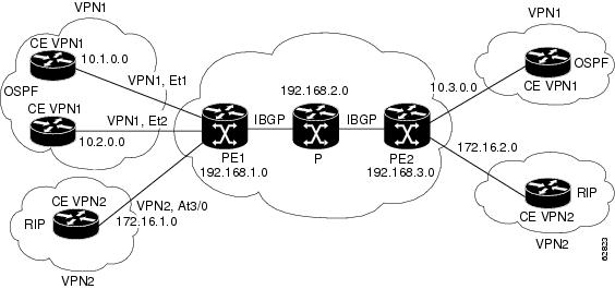
Figure 1 shows a simple MPLS VPN configuration. This configuration includes two customer MPLS VPNs (labeled VPN1 and VPN2) and a simple provider network that consists of two PE routers (labeled PE1 and PE2) and a provider core router labeled P. Figure 1 shows the following sample configuration:
•![]() VRF names—VPN1 and VPN2
VRF names—VPN1 and VPN2
•![]() Interfaces associated with VRFs—Et1, Et2, and At3/0
Interfaces associated with VRFs—Et1, Et2, and At3/0
•![]() Routing protocols—Open Shortest Path First (OSPF), Routing Information Protocol (RIP), and Interior Border Gateway Protocol (IBGP)
Routing protocols—Open Shortest Path First (OSPF), Routing Information Protocol (RIP), and Interior Border Gateway Protocol (IBGP)
•![]() Routes associated with VPN1—10.1.0.0, 10.2.0.0, and 10.3.0.0
Routes associated with VPN1—10.1.0.0, 10.2.0.0, and 10.3.0.0
•![]() Routes associated with VPN2—172.16.1.0 and 172.16.2.0
Routes associated with VPN2—172.16.1.0 and 172.16.2.0
•![]() Routes associated with the provider network—192.168.1.0, 192.168.2.0, and 192.168.3.0
Routes associated with the provider network—192.168.1.0, 192.168.2.0, and 192.168.3.0
This configuration is used to explain MPLS VPN events that are monitored and managed by the MPLS-L3VPN-STD-MIB.
Figure 1 Sample MPLS Layer 3 VPN Configuration
For information on IPv6 VPN over MPLS (6VPE) configuration, see the "Implementing IPv6 VPN over MPLS (6VPE)" chapter in the Cisco IOS IPv6 Configuration Guide.
MPLS-L3VPN-STD-MIB Scalar Objects
MPLS-L3VPN-STD-MIB defines several scalar objects. Table 1 describes the scalar objects that are implemented for Cisco IOS Release 12.2(33)SRC and Release 12.2(33)SB.
MPLS-L3VPN-STD-MIB MIB Tables
•![]() VRF Configuration Table (mplsL3VpnVrfTable)
VRF Configuration Table (mplsL3VpnVrfTable)
•![]() VPN Interface Configuration Table (mplsL3VpnIfConfTable)
VPN Interface Configuration Table (mplsL3VpnIfConfTable)
•![]() VRF Route Target Table (mplsL3VpnVrfRTTable)
VRF Route Target Table (mplsL3VpnVrfRTTable)
•![]() VRF Security Table (mplsL3VpnVrfSecTable)
VRF Security Table (mplsL3VpnVrfSecTable)
•![]() VRF Performance Table (mplsL3VpnVrfPerfTable)
VRF Performance Table (mplsL3VpnVrfPerfTable)
•![]() VRF Routing Table (mplsL3VpnVrfRteTable)
VRF Routing Table (mplsL3VpnVrfRteTable)
VRF Configuration Table (mplsL3VpnVrfTable)
Entries in the VRF configuration table (mplsL3VpnVrfTable) represent the VRF instances that are configured on the router. These include recently deleted VRFs. The information in this table is also displayed in the output of the show vrf detail command.
Each VRF is referenced by its VRF name (mplsL3VpnVrfName).
Table 2 lists MPLS Layer 3 VPN information and the associated MIB objects supported by the VRF configuration table (mplsL3VpnVrfTable).
|
|
|
|---|---|
mplsL3VpnVrfName |
The name associated with this VRF. When this object is used as an index to a table, the first octet is the string length, and subsequent octets are the ASCII codes of each character. For example, "vpn1" is represented as 4.118.112.110.49. The VRF name can be equivalent to the VPN ID. If the VRF name is equivalent to the VPN ID, the VRF name must be equivalent to the value for the mplsL3VpnVrfVpnId MIB object. We recommend that all sites that support VRFs that are part of the same VPN use the same naming convention for VRFs and use the same VPN ID. |
mplsL3VpnVrfVpnId |
The VPN identification number based on RFC 2685. If you do not specify a VPN ID, the value is an empty string. |
mplsL3VpnVrfDescription |
The description of the VRF. This is specified with the description command in VRF configuration mode: Router(config)# vrf definition vrf-name Router(config-vrf)# description vrf-description Note |
mplsL3VpnVrfRD |
The route distinguisher for this VRF. This is specified with the rd command in VRF configuration mode: Router(config)# vrf definition vrf-name Router(config-vrf)# rd route-distinguisher Note |
mplsL3VpnVrfCreationTime |
The value of the sysUpTime when this VRF entry was created. |
mplsL3VpnVrfOperStatus |
The operational status of this VRF. A VRF is up (1) when at least one interface associated with the VRF is up. A VRF is down (2) when: • • |
mplsL3VpnVrfActiveInterfaces |
The number of interfaces assigned to this VRF that are operationally up. |
mplsL3VpnVrfAssociatedInterfaces |
The number of interfaces assigned to this VRF, independent of the operational status. |
mplsL3VpnVrfConfMidRteThresh |
The middle threshold. If the number of routes in the VRF crosses this threshold, an mplsL3VpnVrfRouteMidThreshExceeded notification is sent (if notifications are enabled and configured). You can set this value in VRF address family configuration mode as a percentage of the maximum with the maximum routes limit {warn-threshold | warn-only} command. For example, the following maximum routes command sets the warning threshold for an IPv4 address family in VRF vpn1 as 50 percent of the maximum route threshold: Router(config)# vrf definition vpn1 Router(config-vrf)# address-family ipv4 Router(config-vrf-af)# maximum routes 1000 50 If vpn1 also has an IPv6 address family configured, the following maximum routes command sets the warning threshold for the IPv6 address family as 50 percent of its maximum route threshold: Router(config)# vrf definition vpn1 Router(config-vrf)# address-family 1pv6 Router(config-vrf-af)# maximum routes 2000 50 Note If both IPv4 and IPv6 address-family configurations are present in the VRF, the threshold is an aggregate of the warning threshold values. In this example, the aggregate warning threshold is 1500 routes [(ipv4 = 500) + (ipv6 = 1000)]. An mplsL3VpnVrfRouteMidThreshExceeded notification is not sent until both address families reach their warning threshold. If only a single address family exists for the VRF, the mplsL3VpnVrfRouteMidThreshExceeded notification is sent when the warning threshold is reached for the single address family. The following command sets a middle threshold of 1000 routes. An mplsL3VrfRouteMidThreshExceeded notification is sent when this threshold is exceeded. However, additional routes are still allowed because a maximum route threshold is not set with this command. Router(config-vrf-if)# maximum routes 1000 warn-only See the "MPLS-L3VPN-STD-MIB Notification Events" section for more information on the mplsL3VpnVrfRouteMidThreshExceeded notification. |
mplsL3VpnVrfConfHighRteThresh |
The maximum route threshold. If the number of routes in the VRF crosses this threshold, an mplsL3VpnVrfNumVrfRouteMaxThreshExceeded notification is sent (if notifications are enabled and configured). You can set this value in VRF address family configuration mode with the maximum routes limit {warn-threshold | warn-only} command as follows: Router(config)# vrf definition vpn2 Router(config-vrf)# address-family ipv4 Router(config-vrf-af)# maximum routes 1000 75 Router(config)# vrf definition vpn2 Router(config-vrf)# address-family ipv6 Router(config-vrf-af)# maximum routes 2000 75 Note If both IPv4 and IPv6 address-family configurations are present in the VRF, the threshold is an aggregate of the maximum threshold values. In this example, the aggregate maximum route threshold is 3000 [(ipv4 = 1000)+ (ipv6 = 2000)]. An mplsL3VpnVrfNumVrfRouteMaxThreshExceeded notification is not sent until both address families reaches their maximum route threshold. If only a single address family exists for the VRF, the mplsL3VpnVrfRouteMaxThreshExceeded notification is sent when the maximum route threshold is reached for the single address family. Routes are not added to the address-family that has already reached its maximum route threshold. See the "MPLS-L3VPN-STD-MIB Notification Events" section for more information on the mplsL3VpnVrfNumVrfRouteMaxThreshExceeded notification. |
mplsL3VpnVrfConfMaxRoutes |
This value is the same as that for mplsL3VpnVrfConfHighRteThresh. |
mplsL3VpnVrfConfLastChanged |
The value of sysUpTime when the configuration of the VRF changes or interfaces are assigned or unassigned from the VRF. Note |
mplsL3VpnVrfConfRowStatus |
The status of a row in the table. This object normally reads "active (1)," but may read "notInService (2)" if a VRF was recently deleted. |
mplsL3VpnVrfConfAdminStatus |
The operation status of the VRF. The possible values are: • • |
mplsL3VpnVrfConfStorageType |
The storage type for the VRF entry. This object always returns a value of "volatile (2)." |
VPN Interface Configuration Table (mplsL3VpnIfConfTable)
In Cisco IOS software, a VRF is associated with one MPLS Layer 3 VPN. Zero or more interfaces can be associated with a VRF. A VRF uses an interface that is defined in the ifTable of the Interfaces Group of MIB II (IFMIB). The IFMIB defines objects for managing interfaces. The ifTable of this MIB contains information on each interface in the network. The mplsL3VpnIfConfTable associates a VRF from the mplsL3VpnVrfTable with a forwarding interface from the ifTable. Figure 2 shows the relationship between VRFs and interfaces defined in the ifTable and the mplsL3VpnIfConfTable.
Figure 2 VRFs, the Interfaces MIB, and the mplsL3VpnIfConfTable

Entries in the VPN interface configuration table (mplsL3VpnIfConfTable) represent the interfaces that are assigned to each VRF. The information available in this table is also displayed in the output of the show vrf command.
The mplsL3VpnIfConfTable shows how interfaces are assigned to VRFs. An LSR creates an entry in this table for every interface capable of supporting MPLS Layer 3 VPNs.
The mplsL3VpnIfConfTable is indexed by the following:
•![]() mplsL3VpnVrfName—The VRF name
mplsL3VpnVrfName—The VRF name
•![]() mplsL3VpnIfConfIndex—An identifier that is the same as the ifIndex from the Interface MIB of the interface assigned to the VRF
mplsL3VpnIfConfIndex—An identifier that is the same as the ifIndex from the Interface MIB of the interface assigned to the VRF
Table 3 lists MPLS Layer 3 VPN information and the associated MIB objects supported by the VPN interface configuration table (mplsL3VpnIfConfTable).
VRF Route Target Table (mplsL3VpnVrfRTTable)
The VRF route target table (mplsL3VpnVrfRTTable) describes the route target communities that are defined for a particular VRF. An LSR creates an entry in this table for each target configured for a VRF supporting an MPLS Layer 3 VPN instance.
The distribution of VPN routing information is controlled through the use of VPN route target communities, implemented by BGP extended communities. Distribution of VPN routing information works as follows:
•![]() When a VPN route learned from a CE router is injected into BGP, a list of VPN route target extended community attributes is associated with it. Typically the list of route target community values is set from an export list of route targets associated with the VRF from which the route was learned.
When a VPN route learned from a CE router is injected into BGP, a list of VPN route target extended community attributes is associated with it. Typically the list of route target community values is set from an export list of route targets associated with the VRF from which the route was learned.
•![]() An import list of route target extended communities is associated with each VRF. The import list defines route target extended community attributes a route must have for the route to be imported into the VRF. For example, if the import list for a particular VRF includes route target communities A, B, and C, then any VPN route that carries any of those route target extended communities—A, B, or C—is imported into the VRF.
An import list of route target extended communities is associated with each VRF. The import list defines route target extended community attributes a route must have for the route to be imported into the VRF. For example, if the import list for a particular VRF includes route target communities A, B, and C, then any VPN route that carries any of those route target extended communities—A, B, or C—is imported into the VRF.
Figure 3 shows a sample configuration and its relationship to an mplsL3VpnVrfRTTable. A route target table exists on each PE router. Routers with route distinguishers (RDs) 100:1, 100:2, and 100:3 are shown in the sample configuration. Routers with RDs 100:4 and 100:5 are not shown in Figure 3, but are included in the route targets for PE2 and in the mplsL3VpnVrfRTTable.
Figure 3 Sample Configuration and the mplsL3VpnVrfRTTable

The mplsL3VpnVrfRTTable shows the import and export route targets for each VRF. The table is indexed by the following:
•![]() mplsL3VpnVrfName—The VRF name
mplsL3VpnVrfName—The VRF name
•![]() mplsL3VpnVrfRTIndex—The route target entry identifier
mplsL3VpnVrfRTIndex—The route target entry identifier
•![]() mplsL3VpnVrfRTType—A value specifying whether the entry is an import route target, is an export route target, or is defined as both
mplsL3VpnVrfRTType—A value specifying whether the entry is an import route target, is an export route target, or is defined as both
Table 4 lists MPLS Layer 3 VPN information and the associated MIB objects supported by the VRF route target table (mplsL3VpnVrfRTTable).
VRF Security Table (mplsL3VpnVrfSecTable)
The VRF security table (mplsL3VpnVrfSecTable) provides information about security for each VRF. An LSR creates an entry in this table for every VRF capable of supporting MPLS Layer 3 VPNs.
The mplsL3VpnVrfSecTable augments the mplsL3VpnVrfTable and has the same indexing.
Table 5 lists MPLS Layer 3 VPN information and the associated MIB objects supported by the VRF security table (mplsL3VpnVrfSecTable).
VRF Performance Table (mplsL3VpnVrfPerfTable)
The VRF performance table (mplsL3VpnVrfPerfTable) provides statistical performance information for each VRF. An LSR creates an entry in this table for every VRF capable of supporting MPLS Layer 3 VPNs.
The mplsL3VpnVrfPerfTable augments the mplsL3VpnVrfTable and has the same indexing.
Table 6 lists the MPLS Layer 3 VPN information and the associated MIB objects supported by the VRF performance table (mplsL3VpnVrfPerfTable).
VRF Routing Table (mplsL3VpnVrfRteTable)
The VRF routing table (mplsL3VpnVrfRteTable) provides per-interface routing table information for each MPLS Layer 3 VPN VRF.
The information available in this table can also be displayed with the show ip route vrf vrf-name command for IPv4 routes or the show ipv6 route vrf vrf-name command for IPv6 routes.
•![]() For example, for PE1 in Figure 1, with the show ip route vrf vpn1 command, you would see results like the following:
For example, for PE1 in Figure 1, with the show ip route vrf vpn1 command, you would see results like the following:
Router# show ip route vrf vpn1
Codes: C - connected, S - static, I - IGRP, R - RIP, M - mobile, B - BGP
D - EIGRP, EX - EIGRP external, O - OSPF, IA - OSPF inter area
N1 - OSPF NSSA external type 1, N2 - OSPF NSSA external type 2
E1 - OSPF external type 1, E2 - OSPF external type 2, E - EGP
i - IS-IS, L1 - IS-IS level-1, L2 - IS-IS level-2, ia - IS-IS inter area
* - candidate default, U - per-user static route, o - ODR
P - periodic downloaded static route
!
Gateway of last resort is not set
!
10.0.0.0/32 is subnetted, 3 subnets
B 10.3.0.0 [200/0] via 192.168.2.1, 04:36:33
C 10.1.0.0/16 is directly connected, Ethernet1
C 10.2.0.0/16 [200/0] directly connected Ethernet2, 04:36:33
•![]() With the show ip route vrf vpn2 command, you would see results like the following:
With the show ip route vrf vpn2 command, you would see results like the following:
Router# show ip route vrf vpn2
Codes: C - connected, S - static, I - IGRP, R - RIP, M - mobile, B - BGP
D - EIGRP, EX - EIGRP external, O - OSPF, IA - OSPF inter area
N1 - OSPF NSSA external type 1, N2 - OSPF NSSA external type 2
E1 - OSPF external type 1, E2 - OSPF external type 2, E - EGP
i - IS-IS, L1 - IS-IS level-1, L2 - IS-IS level-2, ia - IS-IS inter area
* - candidate default, U - per-user static route, o - ODR
P - periodic downloaded static route
!
Gateway of last resort is not set
!
172.16.0.0/32 is subnetted, 2 subnets
B 172.16.2.0 [200/0] via 192.168.2.1, 04:36:33
C 172.16.1.0 is directly connected, ATM 3/0
•![]() The following is sample IPv6 output associated with a VRF named vrf3 that you would see with the show ipv6 route vrf command:
The following is sample IPv6 output associated with a VRF named vrf3 that you would see with the show ipv6 route vrf command:
Router# show ipv6 route vrf vrf3
IPv6 Routing Table vrf3 - 6 entries
Codes: C - Connected, L - Local, S - Static, R - RIP, B - BGP
U - Per-user Static route
I1 - ISIS L1, I2 - ISIS L2, IA - ISIS interarea
O - OSPF intra, OI - OSPF inter, OE1 - OSPF ext 1, OE2 - OSPF ext 2
C 2001:8::/64 [0/0]
via ::, FastEthernet0/0
L 2001:8::3/128 [0/0]
via ::, FastEthernet0/0
B 2002:8::/64 [200/0]
via ::FFFF:192.168.1.4,
B 2010::/64 [20/1]
via 2001:8::1,
C 2012::/64 [0/0]
via ::, Loopback1
L 2012::1/128 [0/0]
via ::, Loopback1
Figure 4 shows the relationship of the routing tables, the VRFs, and the mplsL3VpnVrfRteTable. You can display information about the VPN1 and VPN2 route tables using the show ip route vrf vrf-name command. The global route table for IPv4 routes is the same as ipCidrRouteTable in the IP-FORWARD-MIB. You can display information about the global route table with the show ip route command.
Figure 4 IPv4 Route Table, VRFs, and the mplsL3VpnVrfRteTable

You can display information about IPv6 route tables using the show ipv6 route vrf {vrf-name | vrf-number} command. The global route table for IPv6 routes is the same as inetCidrRouteTable in the IP-FORWARD-MIB. You can display information about the global route table with the show ipv6 route command.
Figure 5 illustrates a multiprotocol VRF, in which the VRF named vrf1 is enabled for both IPv4 and IPv6 routes and is associated with two interfaces (IF1, IF2), two sets of tables (IPv4 RIB and FIB and IPv6 RIB and FIB), and a set of common or distinct policies.
Figure 5 Multiprotocol VRF

An LSR creates an entry in the mplsL3VpnVrfRteTable for every route that is configured, either dynamically or statically, within the context of a specific VRF capable of supporting MPLS Layer 3 VPNs.
The mplsL3VpnVrfRteTable is indexed by the following:
•![]() mplsL3VpnVrfName—The VRF name, which provides the VRF routing context
mplsL3VpnVrfName—The VRF name, which provides the VRF routing context
•![]() mplsL3VpnVrfRteInetCidrDestType—The destination address type (IPv4 or IPv6)
mplsL3VpnVrfRteInetCidrDestType—The destination address type (IPv4 or IPv6)
•![]() mplsL3VpnVrfRteInetCidrDest—The destination IPv4 or IPv6 address
mplsL3VpnVrfRteInetCidrDest—The destination IPv4 or IPv6 address
•![]() mplsL3VpnVrfRteInetCidrPfxLen—The length of the prefix for the IP destination address
mplsL3VpnVrfRteInetCidrPfxLen—The length of the prefix for the IP destination address
•![]() mplsL3VpnVrfRteInetCidrPolicy—An index that distinguishes between multiple paths to the same destination
mplsL3VpnVrfRteInetCidrPolicy—An index that distinguishes between multiple paths to the same destination
•![]() mplsL3VpnVrfRteInetCidrNHopType—The address type of the next hop IP address (IPv4 or IPv6)
mplsL3VpnVrfRteInetCidrNHopType—The address type of the next hop IP address (IPv4 or IPv6)
•![]() mplsL3VpnVrfRteInetCidrNextHop—The IP address of the next hop for each route entry
mplsL3VpnVrfRteInetCidrNextHop—The IP address of the next hop for each route entry
Table 7 lists MPLS Layer 3 VPN information for the MIB objects supported by the VRF routing table (mplsL3VpnVrfRteTable). This table represents VRF-specific routes. The global routing table is the ipCidrRouteTable (IPv4 routes) or inetCidrRouteTable (IPv6 routes) in the IP-FORWARD-MIB.
MPLS-L3VPN-STD-MIB Notification Events
The following notifications of the MPLS-L3VPN-STD-MIB are supported:
•![]() mplsL3VpnVrfUp—This notification indicates that the VRF is up. It is generated and sent to an NMS when one interface associated with the VRF is brought up, after previously all interfaces were in the down state.
mplsL3VpnVrfUp—This notification indicates that the VRF is up. It is generated and sent to an NMS when one interface associated with the VRF is brought up, after previously all interfaces were in the down state.
•![]() mplsL3VpnVrfDown—This notification indicates that the VRF is down. It is generated and sent to the NMS when the last interface associated with the VRF is brought down, after all other interfaces associated with the VRF are already in the down state.
mplsL3VpnVrfDown—This notification indicates that the VRF is down. It is generated and sent to the NMS when the last interface associated with the VRF is brought down, after all other interfaces associated with the VRF are already in the down state.
•![]() mplsL3VpnVrfRouteMidThreshExceeded—This notification is generated and sent when the middle or warning threshold, mplsL3VpnVrfMidRouteThreshold, is crossed. You can configure this threshold in the CLI by using the following commands:
mplsL3VpnVrfRouteMidThreshExceeded—This notification is generated and sent when the middle or warning threshold, mplsL3VpnVrfMidRouteThreshold, is crossed. You can configure this threshold in the CLI by using the following commands:
Router(config)# vrf definition vrf-name
Router(config-vrf)# address-family {ipv4 |ipv6}
Router(config-vrf-af)# maximum routes limit warn-threshold [% of max)
The warn-threshold argument is a percentage of the maximum routes specified by the limit argument. You can also configure a middle threshold with the following command, in which the limit argument represents the warning threshold:
Router(config-vrf-af)# maximum routes limit warn-only
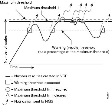
This notification is sent to the NMS only at the time the threshold is exceeded. (See Figure 6 for a comparison of the warning and maximum thresholds.) Whenever the number of routes falls below this threshold and exceeds the threshold again, a notification is sent to the NMS.
If both IPv4 and IPv6 address-family configurations are present in the VRF, the threshold is an aggregate of the warning threshold values. An mplsL3VpnVrfRouteMidThreshExceeded notification is not sent until the second address family reaches its warning threshold.
•![]() mplsL3VpnVrfNumVrfRouteMaxThreshExceeded—This notification is generated and sent when you attempt to create a route on a VRF that already contains the maximum number of routes indicated by the mplsL3VpnVrfMaxRouteThreshold object. The maximum number of routes is defined by the limit argument of the maximum routes commands:
mplsL3VpnVrfNumVrfRouteMaxThreshExceeded—This notification is generated and sent when you attempt to create a route on a VRF that already contains the maximum number of routes indicated by the mplsL3VpnVrfMaxRouteThreshold object. The maximum number of routes is defined by the limit argument of the maximum routes commands:
Router(config)# vrf definition vrf-name
Router(config-vrf)# address-family {ipv4 |ipv6}
Router(config-vrf-af)# maximum routes limit warn-threshold [% of max]
A trap notification is sent to the NMS when you attempt to exceed the maximum threshold. Another mplsL3VpnVrfNumVrfRouteMaxThreshExceeded notification is not sent until the number of routes falls below the maximum threshold and reaches the maximum threshold again or if the time interval is reached when the mplsL3VpnVrfConfRteMxThrshTime value is nonzero. (See Figure 6 for an example of how this notification works and for a comparison of the maximum and warning thresholds.)
If an attempt is made to add routes beyond the route limit, SNMP sends a single notification. No other notification is sent until the route count drops below the route limit and another attempt is made to add routes beyond the limit.
However, if you configure the snmp mib mpls vpn max-threshold time command with a value other than 0 (0 is the default), SNMP repeats sending of the notification after the time interval passes if an attempt is made to add another route.
If both IPv4 and IPv6 address-family configurations are present in the VRF, the threshold is an aggregate of the maximum threshold values. An mplsL3VpnVrfNumVrfRouteMaxThreshExceeded notification is not sent until the second address family reaches its maximum route threshold. Routes are not added to the address family that has already reached its maximum route threshold.

Note ![]() If both IPv4 and IPv6 address-family configurations are present in the VRF and one address family does not have a maximum threshold configured, no maximum threshold notification is sent.
If both IPv4 and IPv6 address-family configurations are present in the VRF and one address family does not have a maximum threshold configured, no maximum threshold notification is sent.
•![]() mplsL3VpnNumVrfSecIllglLblThrshExcd—This notification is generated and sent when the number of illegal labels received on a VRF interface as indicated by the mplsL3VpnVrfSecIllegalLblVltns value has exceeded the mplsL3VpnIllLblRcvThrsh value. This threshold is defined with a value of 0. Therefore, a notification is sent when the first illegal label is received on a VRF. Labels are considered illegal if they are outside of the valid label range, do not have a Label Forwarding Information Base (LFIB) entry, or the table ID of the message does not match the table ID for the label in the LFIB.
mplsL3VpnNumVrfSecIllglLblThrshExcd—This notification is generated and sent when the number of illegal labels received on a VRF interface as indicated by the mplsL3VpnVrfSecIllegalLblVltns value has exceeded the mplsL3VpnIllLblRcvThrsh value. This threshold is defined with a value of 0. Therefore, a notification is sent when the first illegal label is received on a VRF. Labels are considered illegal if they are outside of the valid label range, do not have a Label Forwarding Information Base (LFIB) entry, or the table ID of the message does not match the table ID for the label in the LFIB.
•![]() MplsL3VpnNumVrfRouteMaxThreshCleared—Generated and sent when the number of routes on a VRF attempts to exceed the maximum number of routes and then drops below the maximum number of routes. If you attempt to create a route on a VRF that already contains the maximum number of routes, the mplsL3VpnVrfNumVrfRouteMaxThreshExceeded notification is sent (if enabled). When you remove routes from the VRF so that the number of routes falls below the set limit, the MplsL3VpnNumVrfRouteMaxThreshCleared notification is sent. You can clear all routes from the VRF by using the clear ip route vrf command for IPv4 routes and the clear ipv6 route vrf command for IPv6 routes. (See Figure 6 to see when the MplsL3VpnNumVrfRouteMaxThreshCleared notification is sent.)
MplsL3VpnNumVrfRouteMaxThreshCleared—Generated and sent when the number of routes on a VRF attempts to exceed the maximum number of routes and then drops below the maximum number of routes. If you attempt to create a route on a VRF that already contains the maximum number of routes, the mplsL3VpnVrfNumVrfRouteMaxThreshExceeded notification is sent (if enabled). When you remove routes from the VRF so that the number of routes falls below the set limit, the MplsL3VpnNumVrfRouteMaxThreshCleared notification is sent. You can clear all routes from the VRF by using the clear ip route vrf command for IPv4 routes and the clear ipv6 route vrf command for IPv6 routes. (See Figure 6 to see when the MplsL3VpnNumVrfRouteMaxThreshCleared notification is sent.)
Figure 6 Comparison of Warning and Maximum Thresholds
For information on the Cisco IOS CLI commands for configuring MPLS-L3VPN-STD-MIB notifications that are sent to an NMS, see the "How to Configure MPLS EM—MPLS VPN MIB RFC 4382 Upgrade" section.
SNMP Notification Specification for the MPLS-L3VPN-STD-MIB
In an SNMPv1 notification, each MPLS Layer 3 VPN notification has a generic type identifier and an enterprise-specific type identifier for identifying the notification type:
•![]() The generic type for all VPN notifications is "enterpriseSpecific" because this is not one of the generic notification types defined for SNMP.
The generic type for all VPN notifications is "enterpriseSpecific" because this is not one of the generic notification types defined for SNMP.
•![]() The enterprise-specific type is identified as follows:
The enterprise-specific type is identified as follows:
–![]() 1 for mplsL3VpnVrfUp
1 for mplsL3VpnVrfUp
–![]() 2 for mplsL3VpnVrfDown
2 for mplsL3VpnVrfDown
–![]() 3 for mplsL3VpnVrfRouteMidThreshExceeded
3 for mplsL3VpnVrfRouteMidThreshExceeded
–![]() 4 for mplsL3VpnVrfNumVrfRouteMaxThreshExceeded
4 for mplsL3VpnVrfNumVrfRouteMaxThreshExceeded
–![]() 5 for mplsL3VpnNumVrfSecIllglLblThrshExcd
5 for mplsL3VpnNumVrfSecIllglLblThrshExcd
–![]() 6 for mplsL3VpnNumVrfRouteMaxThreshCleared
6 for mplsL3VpnNumVrfRouteMaxThreshCleared
In SNMPv2, the notification type is identified by an SnmpTrapOID varbind (variable binding consisting of an object identifier [OID] type and value) included within the notification message:
•![]() The VRF up and down notifications provide additional variables—mplsL3VpnIfConfRowStatus and mplsL3VpnVrfOperStatus—in the notification. These variables describe the SNMP row status and operational status, respectively.
The VRF up and down notifications provide additional variables—mplsL3VpnIfConfRowStatus and mplsL3VpnVrfOperStatus—in the notification. These variables describe the SNMP row status and operational status, respectively.
•![]() The mid threshold notification includes the mplsL3VpnVrfVConfMidRteThresh variable and the mplsL3VpnVrfPerfCurrNumRoutes variable that indicates the current number of routes within the VRF.
The mid threshold notification includes the mplsL3VpnVrfVConfMidRteThresh variable and the mplsL3VpnVrfPerfCurrNumRoutes variable that indicates the current number of routes within the VRF.
•![]() The max threshold notification includes the mplsL3VpnVrfVConfHighRteThresh variable and the mplsL3VpnVrfPerfCurrNumRoutes variable that indicates the current number of routes within the VRF.
The max threshold notification includes the mplsL3VpnVrfVConfHighRteThresh variable and the mplsL3VpnVrfPerfCurrNumRoutes variable that indicates the current number of routes within the VRF.
•![]() The illegal label notification includes the mplsL3VpnVrfSecIllegalLblVltns variable that maintains the current count of illegal labels on a VPN.
The illegal label notification includes the mplsL3VpnVrfSecIllegalLblVltns variable that maintains the current count of illegal labels on a VPN.
•![]() The max threshold cleared notification includes the mplsL3VpnVrfConfHighRteThresh variable and the mplsL3VpnVrfPerfCurrNumRoutes variable that indicates the current number of routes within the VRF.
The max threshold cleared notification includes the mplsL3VpnVrfConfHighRteThresh variable and the mplsL3VpnVrfPerfCurrNumRoutes variable that indicates the current number of routes within the VRF.
MPLS-L3VPN-STD-MIB Notifications Display on Network Management Station
When MPLS-L3VPN-STD-MIB notifications are enabled (see the snmp-server enable traps mpls rfc vpn command), notification messages relating to specific MPLS VPN events within Cisco IOS software are generated and sent to a specified NMS in the network. Any utility that supports SNMPv1 or SNMPv2 notifications can receive notification messages.
To monitor MPLS-L3VPN-STD-MIB notification messages, log in to an NMS that supports a utility that displays SNMP notifications, and start the display utility.
MPLS-L3VPN-STD-MIB Support for IPv6 VPNs over MPLS
The following sections describe how the MPLS-L3VPN-STD-MIB supports IPv6 VPNs over MPLS (6VPE).
•![]() MPLS-L3VPN-STD-MIB Tables and Objects Support for IPv6 VPNs over MPLS
MPLS-L3VPN-STD-MIB Tables and Objects Support for IPv6 VPNs over MPLS
•![]() MPLS-L3VPN-STD-MIB Notifications Support for IPv6 VPNs over MPLS
MPLS-L3VPN-STD-MIB Notifications Support for IPv6 VPNs over MPLS
•![]() Information About Setting Maximum Routes for IPv6 Address-Family VRF Route Limits
Information About Setting Maximum Routes for IPv6 Address-Family VRF Route Limits
MPLS-L3VPN-STD-MIB Tables and Objects Support for IPv6 VPNs over MPLS
The MPLS-L3VPN-STD-MIB gets some of the information to populate the MIB objects from the RIB routing table. For the MPLS-L3VPN-STD-MIB to support IPv6 routes over MPLS, the MIB needs to access the RIB routing tables for both IPv6 and IPv4 for the VRF.
Table 8 describes how the MPLS-L3VPN-STD-MIB supports the MIB tables and objects that are specified by address families or that require routing table information.
|
|
|
|---|---|
VRF route target table (mplsL3VpnVrfRTTable) |
This table lists the route targets specified for the VRF. For IPv6 VPNs over MPLS, route targets can be specified for each address family. The MPLS-L3VPN-STD-MIB retrieves all route targets for IPv4, then retrieves all route targets specified for IPv6. The mplsL3VpnVrfRTDescr object indicates whether a particular route target was defined in an IPv4 or IPv6 address family. |
VRF configuration table (mplsL3VpnVrfTable), mplsL3VpnVrfConfMidRteThresh, mplsL3VpnVrfConfHighRteThresh, mplsL3VpnVrfConfMaxRoutes |
The Cisco IOS CLI allows the setting of maximum and middle threshold values on a per-address-family basis. When both IPv4 and IPv6 address-family configurations exist, the MPLS-L3VPN-STD-MIB displays the aggregate value of these settings (not to exceed the max int32 value). If the maximum route limit is configured for one address family and not for the other address family, the aggregate value is max int32 (4,294,967,295). When only a single address-family configuration exists for the VRF, the MPLS-L3VPN-STD-MIB displays the value as configured for the single address family. For more information on how the MPLS-L3VPN-STD-MIB supports notifications, see the "MPLS-L3VPN-STD-MIB Notifications Display on Network Management Station" section and the "MPLS-L3VPN-STD-MIB Notifications Support for IPv6 VPNs over MPLS" section. |
VRF performance table (mplsL3VpnVrfPerfTable), mplsL3VpnVrfPerfRoutesAdded, mplsL3VpnVrfPerfRoutesDeleted, mplsL3VpnVrfPerfCurrNumRoutes, mplsL3VpnVrfPerfRoutesDropped |
The MPLS-L3VPN-STD-MIB gets the routing table information from IPv4 and routing table information from IPv6, adds the values, and give a cumulative count for each of the VRF performance table objects. |
VRF routing table (mplsL3VpnVrfRteTable) |
This table lists the routes associated with this VRF. The MPLS-L3VPN-STD-MIB needs to get all routes from both the IPv4 route table and IPv6 route table for the VRF. |
VPN interface configuration table (mplsL3VpnIfConfTable), mplsL3VpnIfVpnRouteDistProtocol |
This is a bit mask that indicates the protocol for the interface on which the VRF is defined. The MPLS-L3VPN-STD-MIB needs to get route table information from both the IPv4 address family and the IPv6 address family to look up the protocol and bits to set. This MPLS-L3VPN-STD-MIB information is a union of the IPv4 and IPv6 configurations in the VRF. |
MPLS-L3VPN-STD-MIB Notifications Support for IPv6 VPNs over MPLS
This section explains how the MPLS-L3VPN-STD-MIB handles the mplsL3VpnVrfRouteMidThreshExceeded, mplsL3VpnVrfNumVrfRouteMaxThreshExceeded, and mplsL3VpnNumVrfRouteMaxThreshCleared notifications.
Notifications for exceeding the route limit for the middle (mplsL3VpnVrfRouteMidThreshExceeded) and maximum (mplsL3VpnVrfNumVrfRouteMaxThreshExceeded) thresholds are triggered by the route table when there is an attempt to add a new route after the number of routes has reached the threshold. With MIB support for both IPv6 and IPv4, two separate route tables could exist for the VRF. When the maximum or middle threshold is exceeded, MPLS-L3VPN-STD-MIB sends notifications to an NMS if you configured these thresholds.
MPLS-L3VPN-STD-MIB manages the maximum and middle thresholds based on an address-family configuration. For Cisco IOS Releases 12.2(33)SRC and 12.2(33)SB, the MPLS-L3VPN-STD-MIB triggers a notification (or trap) based on the aggregate of the IPv4 and IPv6 maximum and middle threshold values.
Note ![]() A maximum command is introduced in Cisco IOS Release 12.2(33)SRC for the IPv6 address family.
A maximum command is introduced in Cisco IOS Release 12.2(33)SRC for the IPv6 address family.
The MPLS-L3VPN-STD-MIB manages the aggregate threshold values as described in the following scenarios:
•![]() Scenario 1: One address family is configured (IPv4 or IPv6); the address family contains maximum and middle threshold configurations:
Scenario 1: One address family is configured (IPv4 or IPv6); the address family contains maximum and middle threshold configurations:
–![]() The aggregate max-threshold value is equal to the address family-specific max-route value.
The aggregate max-threshold value is equal to the address family-specific max-route value.
–![]() The aggregate mid-threshold value is equal to the address family-specific mid-route value.
The aggregate mid-threshold value is equal to the address family-specific mid-route value.
–![]() Address family routes stop adding to the routing table when the number of routes reaches the maximum threshold set for the address family. A notification or trap is sent with the next attempt to add a route.
Address family routes stop adding to the routing table when the number of routes reaches the maximum threshold set for the address family. A notification or trap is sent with the next attempt to add a route.
•![]() Scenario 2: Both IPv4 and IPv6 address families are configured; both contain maximum and middle threshold configurations:
Scenario 2: Both IPv4 and IPv6 address families are configured; both contain maximum and middle threshold configurations:
–![]() The aggregate max-threshold value is equal to the sum of the IPv4 and IPv6 max-threshold values (with the upper limit set to a maximum value of 4,294,967,295).
The aggregate max-threshold value is equal to the sum of the IPv4 and IPv6 max-threshold values (with the upper limit set to a maximum value of 4,294,967,295).
–![]() The aggregate mid-threshold value is equal to the sum of the IPv4 and IPv6 mid-threshold values. Only when both address families have reached the mid-threshold limit is the notification sent.
The aggregate mid-threshold value is equal to the sum of the IPv4 and IPv6 mid-threshold values. Only when both address families have reached the mid-threshold limit is the notification sent.
–![]() Address family routes stop adding to the routing table when the number of routes reaches the maximum threshold per address family. A notification or trap is not sent until both IPv4 and IPv6 routes reach the maximum threshold.
Address family routes stop adding to the routing table when the number of routes reaches the maximum threshold per address family. A notification or trap is not sent until both IPv4 and IPv6 routes reach the maximum threshold.
•![]() Scenario 3: Both IPv4 and IPv6 address families are configured; only one contains a maximum and middle route threshold configuration:
Scenario 3: Both IPv4 and IPv6 address families are configured; only one contains a maximum and middle route threshold configuration:
–![]() The aggregate max-threshold value is equal to the maximum threshold value (4,294,967,295).
The aggregate max-threshold value is equal to the maximum threshold value (4,294,967,295).
–![]() The aggregate mid-threshold value is equal to the maximum threshold value (4,294,967,295).
The aggregate mid-threshold value is equal to the maximum threshold value (4,294,967,295).
–![]() Address family routes stop adding to the routing table for the address family that contains the maximum threshold configuration when the number of routes reaches the maximum threshold for the address family. However, no notification or trap is sent.
Address family routes stop adding to the routing table for the address family that contains the maximum threshold configuration when the number of routes reaches the maximum threshold for the address family. However, no notification or trap is sent.
Note ![]() If you configure a single address-family VRF with a maximum and middle threshold (Scenario 1), and later add the other address-family configuration to your VRF without configuring a maximum threshold (Scenario 3), you no longer receive a maximum threshold notification for the original address family when the threshold is reached, but routes would no longer be added to the routing table for this address family.
If you configure a single address-family VRF with a maximum and middle threshold (Scenario 1), and later add the other address-family configuration to your VRF without configuring a maximum threshold (Scenario 3), you no longer receive a maximum threshold notification for the original address family when the threshold is reached, but routes would no longer be added to the routing table for this address family.
Information About Setting Maximum Routes for IPv6 Address-Family VRF Route Limits
You should understand the following before you set maximum routes for the IPv6 address family:
•![]() The maximum routes command is entered in address-family configuration mode (the address-family ipv6 or address-family ipv4 command) for the specified VRF.
The maximum routes command is entered in address-family configuration mode (the address-family ipv6 or address-family ipv4 command) for the specified VRF.
•![]() If you attempt to set the maximum route limit below the current number of routes in theIPv6 routing table for the VRF, the CLI command is rejected. You cannot downsize the IPv6 routing table.
If you attempt to set the maximum route limit below the current number of routes in theIPv6 routing table for the VRF, the CLI command is rejected. You cannot downsize the IPv6 routing table.
If you configure a warning-only threshold, the command is accepted, but the route limit is not enforced. This statement also applies to IPv4.
•![]() If the routing table has exceeded its route limit, the output from show ipv6 route vrf command displays an error message that indicates that the RIB has overflowed.
If the routing table has exceeded its route limit, the output from show ipv6 route vrf command displays an error message that indicates that the RIB has overflowed.
•![]() If the routing table does not automatically recover from the overflow condition when the number of routes drops below the enforced limit, you would need to enter the clear ipv6 route vrf command. This forces the routing table to purge and repopulate.
If the routing table does not automatically recover from the overflow condition when the number of routes drops below the enforced limit, you would need to enter the clear ipv6 route vrf command. This forces the routing table to purge and repopulate.
If the repopulate is successful, then the error condition is cleared. If the automatic or manual purging and repopulate are unsuccessful, the error message in the show ipv6 route vrf command output remains.
•![]() For Cisco IOS Releases 12.2(1st)SRC and 12.2(33)SB, the notifications generated in the MPLS-L3VPN-STD-MIB for the route maximum, middle, 3or warnings, and for threshold-cleared objects are an aggregate of the IPv4 and IPv6 route limits and route counts when both routing tables are configured for the VRF.
For Cisco IOS Releases 12.2(1st)SRC and 12.2(33)SB, the notifications generated in the MPLS-L3VPN-STD-MIB for the route maximum, middle, 3or warnings, and for threshold-cleared objects are an aggregate of the IPv4 and IPv6 route limits and route counts when both routing tables are configured for the VRF.
MPLS-L3VPN-STD-MIB Data Security
Requirements of the network-facing operator and customers to ensure MPLS-L3VPN-STD-MIB data security are as follows:
•![]() Network-facing operators need to poll all the data in the VRF-aware MPLS-L3VPN-STD-MIB without compromising security. Operators managing the network need to poll all available data in a single SNMP walk.
Network-facing operators need to poll all the data in the VRF-aware MPLS-L3VPN-STD-MIB without compromising security. Operators managing the network need to poll all available data in a single SNMP walk.
•![]() Customers managing VRFs from an NMS need to be able to poll data only on VRFs for which they are responsible. Customer VRF information should be visible only to that particular customer. In the configuration example that follows, the customer associated with VRF vrf1 should see only VRF vrf1 information and the customer associated with VRF vrf2 should see only VRF vrf2 information.
Customers managing VRFs from an NMS need to be able to poll data only on VRFs for which they are responsible. Customer VRF information should be visible only to that particular customer. In the configuration example that follows, the customer associated with VRF vrf1 should see only VRF vrf1 information and the customer associated with VRF vrf2 should see only VRF vrf2 information.
Network operators can enter an snmp-server community command that contains an access control list (ACL) to make sure that all data is accessible in a single SNMP walk and that customer routers cannot access the data. For example, the operator can enter the following global configuration command: snmp-server community any-community-name rw access-list acl-number. The acl-number argument can be configured to allow requests from the PE network. This ensures that customer-facing routers cannot access any data using the specified community string.
To ensure that a customer's VRF information is secure, you can configure an SMNP context that is peculiar to the customer's VRF. For example, the following sample configuration ensures that the customer associated with VRF vrf1 and the customer associated with VRF vrf2 both connected to the same PE can access information pertaining only to their own VRF and nothing else:
!
vrf definition vrf1
rd 100:110
!
address-family ipv4
route-target export 100:1000
route-target import 100:1000
exit-address-family
!
vrf definition vrf2
rd 100:120
!
address-family ipv4
route-target export 100:2000
route-target import 100:2000
exit-address-family
!
interface Ethernet3/1
description Belongs to VPN vrf1
vrf forwarding vrf1
ip address 10.20.1.20 255.255.0.0
!
interface Ethernet3/2
description Belongs to vrf2
vrf forwarding vrf2
ip address 10.30.1.10 255.255.0.0
!
access-list 10 permit 10.20.1.21
access-list 10 deny any
access-list 20 permit 10.30.1.11
access-list 20 deny any
!
snmp-server view vrf1View mplsL3VpnMIB.*.*.*.*.*.3.114.101.100 included
snmp-server view vrf2View mplsL3VpnMIB.*.*.*.*.*.5.103.114.101.101.110 included
!
snmp-server community vrf1Comm view vrf1View rw 10
snmp-server community vrf2Comm view vrf2View rw 20
!
Note ![]() The snmp-server view commands include mplsL3VpnMIB with OIDs in this format: mplsL3VpnMIB.*.*.*.*.*.length-of-vrf-name.vrf-name-converted-to-octet-character-representation-
The snmp-server view commands include mplsL3VpnMIB with OIDs in this format: mplsL3VpnMIB.*.*.*.*.*.length-of-vrf-name.vrf-name-converted-to-octet-character-representation-
of-the-name. For example:
•![]() VRF vrf1 would be represented as 3.114.101.100.
VRF vrf1 would be represented as 3.114.101.100.
•![]() VRF vrf2 would be represented as 5.103.114.101.101.110.
VRF vrf2 would be represented as 5.103.114.101.101.110.

Major Differences Between the MPLS-VPN-MIB and the MPLS-L3VPN-STD-MIB
The MPLS-L3VPN-STD-MIB based on RFC 4382 provides the same basic functionality as the MPLS-VPN-MIB, draft Version 3 (draft-ieft-ppvpn-mpls-vpn-mib-03.txt). They both provide an interface for MPLS Layer 3 VPNs through the use of SNMP.
After the implementation of the MPLS-L3VPN-STD-MIB (RFC 4382) in Cisco IOS Release 12.2(33)SRC, the MPLS-VPN-MIB will exist for a period of time before support is completely removed. This gives you the chance to migrate to the MPLS-L3VPN-STD-MIB. Both MIBs can coexist in the same image because the MPLS-L3VPN-STD-MIB and the MPLS-VPN-MIB have different root OIDs.
The following sections provide information about the major differences between the MPLS-VPN-MIB and the MPLS-L3VPN-STD-MIB:
•![]() Global Name Changes for the MPLS-L3VPN-STD-MIB Objects
Global Name Changes for the MPLS-L3VPN-STD-MIB Objects
•![]() MPLS-VPN-MIB and MPLS-L3VPN-STD-MIB Scalar Object Differences
MPLS-VPN-MIB and MPLS-L3VPN-STD-MIB Scalar Object Differences
•![]() MPLS-VPN-MIB and MPLS-L3VPN-STD-MIB Table Object Differences
MPLS-VPN-MIB and MPLS-L3VPN-STD-MIB Table Object Differences
•![]() Tables Not Supported in the MPLS-L3VPN-STD-MIB
Tables Not Supported in the MPLS-L3VPN-STD-MIB
•![]() MPLS-VPN-MIB and MPLS-L3VPN-STD-MIB Notification Differences
MPLS-VPN-MIB and MPLS-L3VPN-STD-MIB Notification Differences
Global Name Changes for the MPLS-L3VPN-STD-MIB Objects
For the MPLS-L3VPN-STD-MIB, the names of all objects were changed from mplsVpnname (MPLS-VPN-MIB object name) to mplsL3Vpnname. For example, the VRF configuration table name was changed from mplsVpnVrfTable to mplsL3VpnVrfTable.
The following sections describe major differences between the MPLS-VPN-MIB and the MPLS-L3VPN-STD-MIB objects where the name change is more significant than the global name change.
MPLS-VPN-MIB and MPLS-L3VPN-STD-MIB Scalar Object Differences
Table 9 shows the major difference between the MPLS-VPN-MIB objects and the MPLS-L3VPN-STD-MIB objects for each scalar object.
MPLS-VPN-MIB and MPLS-L3VPN-STD-MIB Table Object Differences
The following tables show the major differences between the MPLS-VPN-MIB and MPLS-L3VPN-STD-MIB objects for each table.
VRF Configuration Table (mplsL3VpnVrfTable)
Table 10 shows the major differences between the MPLS-VPN-MIB objects and the MPLS-L3VPN-STD-MIB objects for the VRF configuration table (mplsL3VpnVrfTable, formerly mplsVpnVrfTable).
VPN Interface Configuration Table (mplsL3VpnIfConfTable)
Table 11 shows the major differences between the MPLS-VPN-MIB objects and the MPLS-L3VPN-STD-MIB objects for the VPN interface configuration table (mplsL3VpnIfConfTable, formerly mplsVpnInterfaceConfTable).
VRF Route Target Table (mplsL3VpnVrfRTTable)
Table 12 shows the major differences between the MPLS-VPN-MIB objects and the MPLS-L3VPN-STD-MIB objects for the VRF route target table (mplsL3VpnVrfRTTable, formerly mplsVpnVrfRouteTargetTable).
VRF Security Table (mplsL3VpnVrfSecTable)
Table 13 shows the major differences between the MPLS-VPN-MIB objects and the MPLS-L3VPN-STD-MIB objects for the VRF security table (mplsL3VpnVrfSecTable, formerly mplsVpnVrfSectTable).
VRF Performance Table (mplsL3VpnVrfPerfTable)
Table 14 shows the major differences between the MPLS-VPN-MIB objects and the MPLS-L3VPN-STD-MIB objects for the VRF performance table (mplsL3VpnVrfPerfTable, formerly mplsVpnVrfPerfTable).
VRF Routing Table (mplsL3VpnVrfRteTable)
Table 14 shows the major differences between the MPLS-VPN-MIB objects and the MPLS-L3VPN-STD-MIB objects for the VRF routing table (mplsL3VpnVrfRteTable, formerly mplsVpnVrfRouteTable).
The indexing for the VRF routing table has also changed:
•![]() MPLS-VPN-MIB indexing—mplsVpnVrfName, mplsVpnVrfRouteDest, mplsVpnVrfRouteMask, mplsVpnVrfRouteTos, mplsVpnVrfRouteNextHop
MPLS-VPN-MIB indexing—mplsVpnVrfName, mplsVpnVrfRouteDest, mplsVpnVrfRouteMask, mplsVpnVrfRouteTos, mplsVpnVrfRouteNextHop
•![]() MPLS-L3VPN-STD-MIB indexing—mplsL3VpnVrfName, mplsL3VpnVrfRteInetCidrDestType, mplsL3VpnVrfRteInetCidrDest, mplsL3VpnVrfRteInetCidrPfxLen, mplsL3VpnVrfRteInetCidrPolicy, mplsL3VpnVrfRteInetCidrNHopType, mplsL3VpnVrfRteInetCidrNextHop
MPLS-L3VPN-STD-MIB indexing—mplsL3VpnVrfName, mplsL3VpnVrfRteInetCidrDestType, mplsL3VpnVrfRteInetCidrDest, mplsL3VpnVrfRteInetCidrPfxLen, mplsL3VpnVrfRteInetCidrPolicy, mplsL3VpnVrfRteInetCidrNHopType, mplsL3VpnVrfRteInetCidrNextHop
Tables Not Supported in the MPLS-L3VPN-STD-MIB
The following tables from the MPLS-VPN-MIB are deleted in the MPLS-L3VPN-STD-MIB (RFC 4382):
•![]() BGP neighbor address table (mplsVpnVrfBgpNbrAddrTable)
BGP neighbor address table (mplsVpnVrfBgpNbrAddrTable)
•![]() BGP neighbor prefix table (mplsVpnVrfBgpNeighborPrefixTable)
BGP neighbor prefix table (mplsVpnVrfBgpNeighborPrefixTable)
The mplsVpnVrfBgpNeighborPrefixTable was not supported in the Cisco IOS implementation of the MPLS-VPN-MIB.
The Cisco-BGP4-MIB based on Definitions of Managed Objects for BGP-4 (RFC 4273) provides the information related to BGP.
MPLS-VPN-MIB and MPLS-L3VPN-STD-MIB Notification Differences
Table 16 shows the major differences between MPLS-VPN-MIB and the MPLS-L3VPN-STD-MIB notifications.
How to Configure MPLS EM—MPLS VPN MIB RFC 4382 Upgrade
This section contains tasks to configure the MPLS EM—MPLS VPN MIB RFC 4382 Upgrade feature. The MPLS EM—MPLS VPN MIB RFC 4382 Upgrade feature introduces the MPLS-L3VPN-STD-MIB.
Perform the following tasks to configure your router to use SNMP to monitor and manage MPLS Layer 3 VPNs:
•![]() Configuring the SNMP Community (required)
Configuring the SNMP Community (required)
•![]() Configuring the Router to Send MPLS Layer 3 VPN SNMP Notifications to a Host (optional)
Configuring the Router to Send MPLS Layer 3 VPN SNMP Notifications to a Host (optional)
•![]() Configuring Threshold Values for MPLS Layer 3 VPN SNMP Notifications (optional)
Configuring Threshold Values for MPLS Layer 3 VPN SNMP Notifications (optional)
•![]() Example: Configuring SMNP Controls for MPLS Layer 3 VPN Notification Thresholds (optional)
Example: Configuring SMNP Controls for MPLS Layer 3 VPN Notification Thresholds (optional)
Configuring the SNMP Community
The SNMP agent for the MPLS-L3VPN-STD-MIB is disabled by default and must be enabled for you to use SNMP for monitoring and managing MPLS Layer 3 VPNs on your network.
An SNMP community string defines the relationship between the SNMP manager and the agent. The community string acts like a password to regulate access to the agent on the router. The SNMP agent for the MPLS-L3VPN-STD-MIB is enabled when you configure an SNMP community.
Perform this task to configure an SNMP community.
SUMMARY STEPS
1. ![]() enable
enable
2. ![]() show running-config
show running-config
3. ![]() configure terminal
configure terminal
4. ![]() snmp-server community string [view view-name] [ro | rw] [acl-number]
snmp-server community string [view view-name] [ro | rw] [acl-number]
5. ![]() do copy running-config startup-config
do copy running-config startup-config
6. ![]() exit
exit
7. ![]() show running-config | include [option]
show running-config | include [option]
DETAILED STEPS
Configuring the Router to Send MPLS Layer 3 VPN SNMP Notifications to a Host
Perform this task to configure the router to send MPLS Layer 3 VPN SNMP notifications or traps to a host.
The snmp-server host command specifies which hosts receive the notifications. The snmp-server enable traps command globally enables the trap production mechanism for the specified notifications.
For a host to receive a notification, an snmp-server host command must be configured for that host, and, generally, the notification must be enabled globally through the snmp-server enable traps command.
Note ![]() Although you can set the community-string argument using the snmp-server host command by itself, we recommend you define this string using the snmp-server community command before using the snmp-server host command.
Although you can set the community-string argument using the snmp-server host command by itself, we recommend you define this string using the snmp-server community command before using the snmp-server host command.
SUMMARY STEPS
1. ![]() enable
enable
2. ![]() configure terminal
configure terminal
3. ![]() snmp-server host host-addr [traps | informs] [version {1 | 2c | 3 [auth | noauth | priv]}] community-string [udp-port port] [notification-type] [vrf vrf-name]
snmp-server host host-addr [traps | informs] [version {1 | 2c | 3 [auth | noauth | priv]}] community-string [udp-port port] [notification-type] [vrf vrf-name]
4. ![]() snmp-server enable traps mpls rfc vpn [illegal-label] [max-thresh-cleared] [max-threshold] [mid-threshold] [vrf-down] [vrf-up]
snmp-server enable traps mpls rfc vpn [illegal-label] [max-thresh-cleared] [max-threshold] [mid-threshold] [vrf-down] [vrf-up]
5. ![]() end
end
DETAILED STEPS
|
|
|
|
|---|---|---|
Step 1 |
enable Router> enable |
Enables privileged EXEC mode. • |
Step 2 |
configure terminal Router# configure terminal |
Enters global configuration mode. |
Step 3 |
snmp-server host host-addr [traps | informs] [version {1 | 2c | 3 [auth | noauth | priv]}] community-string [udp-port port] [notification-type] [vrf vrf-name] Router(config)# snmp-server host 172.20.2.160 traps comaccess mpls-vpn |
Specifies the recipient of an SNMP notification operation. • • • • – – – • • • • |
Step 4 |
snmp-server enable traps mpls rfc vpn [illegal-label] [max-thresh-cleared] Router(config)# snmp-server enable traps mpls rfc vpn vrf-down vrf-up |
Enables the router to send MPLS Layer 3 VPN-specific SNMP notifications (traps and informs). • • Note • Note • Note • • |
Step 5 |
end Router(config)# end |
(Optional) Exits to privileged EXEC mode. |
Configuring Threshold Values for MPLS Layer 3 VPN SNMP Notifications
Perform this task to configure the following threshold values for MPLS Layer 3 VPN SNMP notifications:
•![]() The mplsL3VpnVrfRouteMidThreshExceeded notification event is generated and sent when the middle threshold (warning) is crossed. You can configure this threshold in the CLI by using the maximum routes command in VRF configuration mode. This notification is sent to the NMS only at the time the threshold is exceeded. Whenever the number of routes falls below this threshold and exceeds the threshold again, a notification is sent to the NMS.
The mplsL3VpnVrfRouteMidThreshExceeded notification event is generated and sent when the middle threshold (warning) is crossed. You can configure this threshold in the CLI by using the maximum routes command in VRF configuration mode. This notification is sent to the NMS only at the time the threshold is exceeded. Whenever the number of routes falls below this threshold and exceeds the threshold again, a notification is sent to the NMS.
If both IPv4 and IPv6 address-family configurations are present in the VRF, the threshold is an aggregate of the warning threshold values. An mplsL3VpnVrfRouteMidThreshExceeded notification is not sent until the second address family reaches its warning threshold.
•![]() The mplsL3VpnVrfNumVrfRouteMaxThreshExceeded notification event is generated and sent when you attempt to create a route on a VRF that already contains the maximum number of routes as defined by the maximum routes command in VRF configuration mode. A trap notification is sent to the NMS when you attempt to exceed the maximum threshold. Another mplsL3VpnVrfNumVrfRouteMaxThreshExceeded notification is not sent until the number of routes falls below the maximum threshold and reaches the maximum threshold again.
The mplsL3VpnVrfNumVrfRouteMaxThreshExceeded notification event is generated and sent when you attempt to create a route on a VRF that already contains the maximum number of routes as defined by the maximum routes command in VRF configuration mode. A trap notification is sent to the NMS when you attempt to exceed the maximum threshold. Another mplsL3VpnVrfNumVrfRouteMaxThreshExceeded notification is not sent until the number of routes falls below the maximum threshold and reaches the maximum threshold again.
If both IPv4 and IPv6 address-family configurations are present in the VRF, the threshold is an aggregate of the maximum threshold values. An mplsL3VpnVrfNumVrfRouteMaxThreshExceeded notification is not sent until the second address family reaches its maximum route threshold. Routes are not added to the address family that has already reached its maximum route threshold.
See Figure 6 for an example of how this notification works and for a comparison of the maximum and warning thresholds.
SUMMARY STEPS
1. ![]() enable
enable
2. ![]() configure terminal
configure terminal
3. ![]() vrf definition vrf-name
vrf definition vrf-name
4. ![]() address-family {ipv4 | ipv6}
address-family {ipv4 | ipv6}
5. ![]() maximum routes limit warn-threshold
maximum routes limit warn-threshold
or
maximum routes limit warn-only
6. ![]() exit-address-family
exit-address-family
7. ![]() end
end
DETAILED STEPS
Configuring SNMP Controls for MPLS VPN Notification Thresholds
Perform this task to configure the following SNMP controls for MPLS VPN notification thresholds:
•![]() The mplsL3VpnVrfConfRteMxThrshTime is the interval at which the maximum route exceeded notification (mplsL3VpnVrfNumVrfRouteMaxThreshExceeded) is reissued after the maximum value is exceeded (or reached) and after the initial notification was sent. You can configure this interval in the CLI by using the snmp mib mpls vpn max-threshold seconds command in global configuration mode. Configure this command if you want to receive more than the initial notification that the maximum route value is exceeded.
The mplsL3VpnVrfConfRteMxThrshTime is the interval at which the maximum route exceeded notification (mplsL3VpnVrfNumVrfRouteMaxThreshExceeded) is reissued after the maximum value is exceeded (or reached) and after the initial notification was sent. You can configure this interval in the CLI by using the snmp mib mpls vpn max-threshold seconds command in global configuration mode. Configure this command if you want to receive more than the initial notification that the maximum route value is exceeded.
•![]() The mplsL3VpnNumVrfSecIllglLblThrshExcd notification is generated and sent when the number of illegal label violations on a VRF has exceeded the number indicated by the mplsL3VpnIllLblRcvThrsh scalar. You can configure the number of illegal labels that generate the mplsL3VpnNumVrfSecIllglLblThrshExcd notification in the CLI by using the snmp mib mpls vpn illegal-label number command in global configuration mode. Configure this command if you want to allow a certain number of illegal label violations before you receive the mplsL3VpnNumVrfSecIllglLblThrshExcd notification.
The mplsL3VpnNumVrfSecIllglLblThrshExcd notification is generated and sent when the number of illegal label violations on a VRF has exceeded the number indicated by the mplsL3VpnIllLblRcvThrsh scalar. You can configure the number of illegal labels that generate the mplsL3VpnNumVrfSecIllglLblThrshExcd notification in the CLI by using the snmp mib mpls vpn illegal-label number command in global configuration mode. Configure this command if you want to allow a certain number of illegal label violations before you receive the mplsL3VpnNumVrfSecIllglLblThrshExcd notification.
SUMMARY STEPS
1. ![]() enable
enable
2. ![]() configure terminal
configure terminal
3. ![]() snmp mib mpls vpn max-threshold seconds
snmp mib mpls vpn max-threshold seconds
4. ![]() snmp mib mpls vpn illegal-label number
snmp mib mpls vpn illegal-label number
5. ![]() end
end
DETAILED STEPS
Configuration Examples for MPLS EM—MPLS VPN MIB RFC 4382 Upgrade
•![]() Example: Configuring the SNMP Community
Example: Configuring the SNMP Community
•![]() Example: Configuring the Router to Send MPLS Layer 3 VPN SNMP Traps
Example: Configuring the Router to Send MPLS Layer 3 VPN SNMP Traps
•![]() Example: Configuring Threshold Values for MPLS Layer 3 VPN SNMP Notifications
Example: Configuring Threshold Values for MPLS Layer 3 VPN SNMP Notifications
•![]() Example: Configuring SMNP Controls for MPLS Layer 3 VPN Notification Thresholds
Example: Configuring SMNP Controls for MPLS Layer 3 VPN Notification Thresholds
Example: Configuring the SNMP Community
The following example shows enabling a simple SNMP community group. This configuration permits any SNMP client to access all MPLS-L3VPN-STD-MIB objects with read-only access using the community string comaccess.
configure terminal
!
snmp-server community comaccess ro
Use the following command to verify that the SNMP master agent is enabled for the MPLS EM—MPLS VPN MIB RFC 4382 Upgrade feature:
Router# show running-config | include snmp-server
Building configuration...
....
snmp-server community comaccess RO
....
Note ![]() If you do not see any "snmp-server" statements, SNMP is not enabled on the router.
If you do not see any "snmp-server" statements, SNMP is not enabled on the router.
Example: Configuring the Router to Send MPLS Layer 3 VPN SNMP Traps
The following example shows you how to enable the router to send MPLS Layer 3 VPN notifications to host 172.20.2.160 using the comaccess community string if a VRF transitions from an up or down state:
configure terminal
!
snmp-server host 172.20.2.160 traps comaccess mpls-vpn
snmp-server enable traps mpls rfc vpn vrf-down vrf-up
Example: Configuring Threshold Values for MPLS Layer 3 VPN SNMP Notifications
The following example shows how to set a maximum threshold of 10,000 routes and a warning threshold that is 80 percent of the maximum threshold for a VRF named vpn1 on a router:
configure terminal
!
vrf definition vpn1
address-family ipv4
maximum routes 10000 80
exit address-family
end
The following example shows how to set a warning threshold of 10,000 routes for a VRF named vpn2 on a router. An error message is generated; however, additional routes are still allowed because a maximum route threshold is not set with this command.
configure terminal
!
vrf definition vpn2
address-family ipv4
maximum routes 10000 warn-only
exit address-family
end
Example: Configuring SMNP Controls for MPLS Layer 3 VPN Notification Thresholds
The following examples show how to configure SNMP controls for MPLS Layer 3 VPN notification thresholds.
In this example, an interval of 2 hours (7200 seconds) is configured for the resending of maximum threshold exceeded notifications after the first notification was sent and the attempt to add routes continues:
configure terminal
!
snmp mib mpls vpn max-threshold 7200
end
If you do not configure an interval to resend maximum route exceeded notifications, SNMP sends a single maximum threshold notification at the time that the maximum threshold is exceeded.
In the following example, the number of illegal labels allowed for a VRF is configured as 5 before SNMP sends an illegal label threshold exceeded notification:
configure terminal
!
snmp mib mpls vpn illegal-label 5
end
If you do not configure an illegal label threshold, then SNMP sends an illegal label notification on the first occurrence of an illegal label.
Additional References
Related Documents
Standards
|
|
|
|---|---|
http://www.rfc-editor.org/rfc/rfc2578.txt |
Structure of Management Information Version 2 (SMIv2) |
MIBs
|
|
|
|---|---|
MPLS-L3VPN-STD-MIB |
To locate and download MIBs for selected platforms, Cisco IOS releases, and feature sets, use Cisco MIB Locator found at the following URL: |
RFCs
Technical Assistance
Feature Information for MPLS EM—MPLS VPN MIB RFC 4382 Upgrade
Table 17 lists the release history for this feature.
Not all commands may be available in your Cisco IOS software release. For release information about a specific command, see the command reference documentation.
Use Cisco Feature Navigator to find information about platform support and software image support. Cisco Feature Navigator enables you to determine which software images support a specific software release, feature set, or platform. To access Cisco Feature Navigator, go to http://www.cisco.com/go/cfn. An account on Cisco.com is not required.
Note ![]() Table 17 lists only the Cisco IOS software release that introduced support for a given feature in a given Cisco IOS software release train. Unless noted otherwise, subsequent releases of that Cisco IOS software release train also support that feature.
Table 17 lists only the Cisco IOS software release that introduced support for a given feature in a given Cisco IOS software release train. Unless noted otherwise, subsequent releases of that Cisco IOS software release train also support that feature.
|
|
|
|
|---|---|---|
MPLS EM—MPLS VPN MIB RFC 4382 Upgrade |
12.2(33)SRC |
The MPLS EM—MPLS VPN MIB RFC 4382 Upgrade feature document describes the MIB that supports Multiprotocol Label Switching (MPLS) Virtual Private Networks (VPNs) based on RFC 4382, MPLS/BGP Virtual Private Network (VPN) Management Information Base. This document also describes the differences between RFC 4382 and the MPLS-VPN-MIB based on the Internet Engineering Task Force (IETF) draft Version 3 (draft-ieft-ppvpn-mpls-vpn-mib-03.txt) and describes the changes needed to implement MPLS-L3VPN-STD-MIB (RFC 4382). The MPLS-VPN-MIB and MPLS-L3VPN-STD-MIB provide an interface for managing the MPLS VPN feature in Cisco IOS software through the use of the Simple Network Management Protocol (SNMP). Cisco IOS MPLS Embedded Management (EM) is a set of standards and value-added services that facilitate the deployment, operation, administration, and management of MPLS-based networks according to the fault, configuration, accounting, performance, and security (FCAPS) model. In 12.2(33)SRC, this feature was introduced on the Cisco 7600 series router. In 12.2(33)SB, the feature was implemented for the Cisco 10000 series router on the Cisco 10000 Performance Routing Engine 2 (PRE-2) and PRE-3. The following sections provide information about this feature: |
| • • • • • • • • • • The following commands were introduced or modified: maximum routes, snmp mib mpls vpn, snmp-server enable traps mpls rfc vpn. |
Glossary
6VPE router—Provider edge router that provides BGP-MPLS IPv6 VPN service over an IPv4-based MPLS core. It is a IPv6 VPN PE, dual-stack router that implements 6PE concepts on the core-facing interfaces.
autonomous system—A collection of networks that share the same routing protocol and that are under the same system administration.
ASN.1—Abstract Syntax Notation One. The data types independent of particular computer structures and representation techniques. Described by ISO International Standard 8824.
BGP—Border Gateway Protocol. The exterior Border Gateway Protocol used to exchange routing information between routers in separate autonomous systems. BGP uses TCP. Because TCP is a reliable protocol, BGP does not experience problems with dropped or fragmented data packets.
BGP prefixes—A route announcement using the BGP. A prefix is composed of a path of autonomous system numbers, indicating which networks the packet must pass through, and the IP block that is being routed. A BGP prefix would look something like: 701 1239 42 206.24.14.0/24. (The /24 part is referred to as a CIDR mask.) The /24 indicates that there are 24 ones in the netmask for this block starting from the left side. A /24 corresponds to the natural mask 255.255.255.0.
CE router—customer edge router. A router on the border between a VPN provider and a VPN customer that belongs to the customer.
CIDR—classless interdomain routing. A technique supported by BGP4 and based on route aggregation. CIDR allows routers to group routes to reduce the quantity of routing information carried by the core routers. With CIDR, several IP networks appear to networks outside the group as a single, larger entity. With CIDR, IP addresses and their subnet masks are written as four octets, separated by periods, followed by a forward slash and a two-digit number that represents the subnet mask.
Cisco Express Forwarding—An advanced Layer 3 IP switching technology. Cisco Express Forwarding optimizes network performance and scalability for networks with large and dynamic traffic patterns.
community—In SNMP, a logical group of managed devices and NMSs in the same administrative domain.
community name—See community string.
community string—A text string that acts as a password and is used to authenticate messages sent between a managed station and a router containing an SNMP agent. The community string is sent in every packet between the manager and the client. Also called a community name.
IETF—Internet Engineering Task Force. A task force consisting of over 80 working groups responsible for developing Internet standards. The IETF operates under the auspices of ISOC. See also ISOC.
informs—A type of notification message that is more reliable than a conventional trap notification message, because the informs message notification requires acknowledgment, and a trap notification does not.
ISOC—Internet Society. An international nonprofit organization, founded in 1992, that coordinates the evolution and use of the Internet. In addition, ISOC delegates authority to other groups related to the Internet, such as the IAB. ISOC is headquartered in Reston, Virginia (United States).
label—A short, fixed-length data construct that tells switching nodes how to forward data (packets or cells).
LDP—Label Distribution Protocol. A standard protocol between MPLS-enabled routers that is used for the negotiation of the labels (addresses) used to forward packets.
LFIB—Label Forwarding Information Base. In the Cisco Label Switching system, the data structure for storing information about incoming and outgoing tags (labels) and associated equivalent packets suitable for labeling.
LSR—label switch router. A device that forwards MPLS packets based on the value of a fixed-length label encapsulated in each packet.
MIB—Management Information Base. A database of network management information that is used and maintained by a network management protocol such as SNMP or CMIP. The value of a MIB object can be changed or retrieved using SNMP or CMIP commands, usually through a GUI network management system. MIB objects are organized in a tree structure that includes public (standard) and private (proprietary) branches.
MPLS—Multiprotocol Label Switching. A method for forwarding packets (frames) through a network. It enables routers at the edge of a network to apply labels to packets (frames). ATM switches or existing routers in the network core can switch packets according to the labels with minimal lookup overhead.
MPLS interface—An interface on which MPLS traffic is enabled.
MPLS VPN—Multiprotocol Label Switching Virtual Private Network. An IP network infrastructure delivering private network services over a public infrastructure using a Layer 3 backbone. Using MPLS VPNs in a Cisco IOS network provides the capability to deploy and administer scalable Layer 3 VPN backbone services including applications, data hosting network commerce, and telephony services to business customers.
For an MPLS VPN solution, an MPLS VPN is a set of provider edge routers that are connected by means of a common "backbone" network to supply private IP interconnectivity between two or more customer sites for a given customer. Each VPN has a set of provisioning templates and policies and can span multiple provider administrative domains (PADs).
NMS—network management system. A powerful, well-equipped computer (typically an engineering workstation) that is used by a network administrator to communicate with other devices in the network. An NMS is typically used to manage network resources, gather statistics, and perform a variety of network administration and configuration tasks.
notification—A message sent by an SNMP agent to a network management station, console, or terminal to indicate that a significant event within Cisco IOS software has occurred. See also trap.
PE router—provider edge router. A router on the border between a VPN provider and a VPN customer that belongs to the provider.
QoS—quality of service. A measure of performance for a transmission system that reflects its transmission quality and service availability.
RIB—Routing Information Base. Also called the routing table.
RT—route target. An extended community attribute that identifies a group of routers and, in each router of that group, a subset of forwarding tables maintained by the router that can be populated with a BGP route carrying that extended community attribute. The RT is a 64-bit value by which Cisco IOS software discriminates routes for route updates in VRFs.
SNMP—Simple Network Management Protocol. The network management protocol used almost exclusively in TCP/IP networks. SNMP provides a means to monitor and control network devices, and to manage configurations, statistics collection, performance, and security. See also SNMP2.
SNMP2—SNMP Version 2. Version 2 of the popular network management protocol. SNMP2 supports centralized and distributed network management strategies, and includes improvements in the Structure of Management Information (SMI), protocol operations, management architecture, and security. See also SNMP.
trap—A message sent by an SNMP agent to a network management station, console, or terminal, indicating that a significant event occurred. Traps (notifications) are less reliable than inform requests, because the receiver does not send an acknowledgment when it receives a trap. The sender cannot determine if the trap was received. See also notification.
VPN—Virtual Private Network. A group of sites that, as the result of a set of administrative policies, are able to communicate with each other over a shared backbone network. A VPN is a secure IP-based network that shares resources on one or more physical networks. A VPN contains geographically dispersed sites that can communicate securely over a shared backbone. See also MPLS VPN.
VPN ID—A mechanism that identifies a VPN based on RFC 2685. A VPN ID consists of an Organizational Unique Identifier (OUI), a three-octet hex number assigned by the IEEE Registration Authority, and a VPN index, a four-octet hex number, which identifies the VPN within the company.
VRF—VPN routing and forwarding instance. A VRF consists of an IP routing table, a derived forwarding table, a set of interfaces that use the forwarding table, and a set of rules and routing protocols that determine what goes into the forwarding table. In general, a VRF includes the routing information that defines a customer VPN site that is attached to a PE router.
 Feedback