-
- MPLS Traffic Engineering - LSP Attributes
- MPLS Traffic Engineering (TE) - Autotunnel Primary and Backup
- MPLS Traffic Engineering - AutoTunnel Mesh Groups
- MPLS Traffic Engineering - Verbatim Path Support
- MPLS Traffic Engineering - RSVP Hello State Timer
- MPLS Traffic Engineering Forwarding Adjacency
- MPLS Traffic Engineering (TE) - Class-based Tunnel Selection
- MPLS Traffic Engineering - Interarea Tunnels
- MPLS TE - Bundled Interface Support
- MPLS Traffic Engineering�Automatic Bandwidth Adjustment for TE Tunnels
- MPLS Point-to-Multipoint Traffic Engineering
- MPLS Traffic Engineering�Tunnel Source
-
- MPLS Traffic Engineering - Inter-AS TE
- MPLS Traffic Engineering - Shared Risk Link Groups
- MPLS Traffic Engineering (TE) - Autotunnel Primary and Backup
- MPLS Traffic Engineering (TE) - Path Protection
- MPLS Traffic Engineering (TE) - Fast Reroute (FRR) Link and Node Protection
- MPLS TE: Link and Node Protection, with RSVP Hellos Support (with Fast Tunnel Interface Down Detection)
- MPLS Traffic Engineering: BFD-triggered Fast Reroute (FRR)
-
- MPLS MTU Command Changes
- AToM Static Pseudowire Provisioning
- MPLS Pseudowire Status Signaling
- L2VPN Interworking
- L2VPN Pseudowire Redundancy
- L2VPN Pseudowire Switching
- VPLS Autodiscovery: BGP Based
- H-VPLS N-PE Redundancy for QinQ and MPLS Access
- L2VPN Multisegment Pseudowires
- QOS Policy Support on L2VPN ATM PVPs
- L2VPN: Pseudowire Preferential Forwarding
-
- Configuring MPLS Layer 3 VPNs
- MPLS VPN Half-Duplex VRF
- MPLS VPN�Show Running VRF
- MPLS VPN�VRF CLI for IPv4 and IPv6 VPNs
- MPLS VPN--BGP Local Convergence
- MPLS VPN�Route Target Rewrite
- MPLS VPN�Per VRF Label
- MPLS VPN 6VPE per VRF Label
- MPLS Multi-VRF (VRF Lite) Support
- BGP Best External
- BGP PIC Edge for IP and MPLS-VPN
- MPLS VPN - L3VPN over GRE
- Dynamic Layer-3 VPNs with Multipoint GRE Tunnels
- MPLS VPN over mGRE
-
- MPLS LSP Ping/Traceroute for LDP/TE, and LSP Ping for VCCV
- MPLS EM�MPLS LSP Multipath Tree Trace
- Pseudowire Emulation Edge-to-Edge MIBs for Ethernet, Frame Relay, and ATM Services
- MPLS Enhancements to Interfaces MIB
- MPLS Label Distribution Protocol MIB Version 8 Upgrade
- MPLS EM�MPLS LDP MIB - RFC 3815
- MPLS Label Switching Router MIB
- MPLS EM�MPLS LSR MIB - RFC 3813
- MPLS Traffic Engineering MIB
- MPLS Traffic Engineering - Fast Reroute MIB
- MPLS EM - TE MIB RFC 3812
- MPLS VPN�MIB Support
- MPLS EM - MPLS VPN MIB RFC4382 Upgrade
-
- MPLS High Availability: Overview
- MPLS High Availability: Command Changes
- MPLS LDP Graceful Restart
- NSF/SSO - MPLS LDP and LDP Graceful Restart
- NSF/SSO: MPLS VPN
- AToM Graceful Restart
- NSF/SSO�Any Transport over MPLS and AToM Graceful Restart
- NSF/SSO - MPLS TE and RSVP Graceful Restart
- ISSU MPLS Clients
- NSF/SSO/ISSU Support for VPLS
- NSF/SSO and ISSU - MPLS VPN 6VPE and 6PE
Cisco IOS Multiprotocol Label Switching Configuration Guide, Release 12.2SR
Bias-Free Language
The documentation set for this product strives to use bias-free language. For the purposes of this documentation set, bias-free is defined as language that does not imply discrimination based on age, disability, gender, racial identity, ethnic identity, sexual orientation, socioeconomic status, and intersectionality. Exceptions may be present in the documentation due to language that is hardcoded in the user interfaces of the product software, language used based on RFP documentation, or language that is used by a referenced third-party product. Learn more about how Cisco is using Inclusive Language.
- Updated:
- April 2, 2008
Chapter: L2VPN Pseudowire Redundancy
- Finding Feature Information
- Contents
- Prerequisites for L2VPN Pseudowire Redundancy
- Restrictions for L2VPN Pseudowire Redundancy
- Information About L2VPN Pseudowire Redundancy
- How to Configure L2VPN Pseudowire Redundancy
- Configuration Examples for L2VPN Pseudowire Redundancy
- Additional References
- Feature Information for L2VPN Pseudowire Redundancy
L2VPN Pseudowire Redundancy
The L2VPN Pseudowire Redundancy feature lets you configure your network to detect a failure in the network and reroute the Layer 2 (L2) service to another endpoint that can continue to provide service. This feature provides the ability to recover from a failure either of the remote provider edge (PE) router or of the link between the PE and customer edge (CE) routers.
Finding Feature Information
Your software release may not support all the features documented in this module. For the latest feature information and caveats, see the release notes for your platform and software release. To find information about the features documented in this module, and to see a list of the releases in which each feature is supported, see the "Feature Information for L2VPN Pseudowire Redundancy" section.
Use Cisco Feature Navigator to find information about platform support and Cisco IOS and Catalyst OS software image support. To access Cisco Feature Navigator, go to http://www.cisco.com/go/cfn. An account on Cisco.com is not required.
Contents
•![]() Prerequisites for L2VPN Pseudowire Redundancy
Prerequisites for L2VPN Pseudowire Redundancy
•![]() Restrictions for L2VPN Pseudowire Redundancy
Restrictions for L2VPN Pseudowire Redundancy
•![]() Information About L2VPN Pseudowire Redundancy
Information About L2VPN Pseudowire Redundancy
•![]() How to Configure L2VPN Pseudowire Redundancy
How to Configure L2VPN Pseudowire Redundancy
•![]() Configuration Examples for L2VPN Pseudowire Redundancy
Configuration Examples for L2VPN Pseudowire Redundancy
•![]() Feature Information for L2VPN Pseudowire Redundancy
Feature Information for L2VPN Pseudowire Redundancy
Prerequisites for L2VPN Pseudowire Redundancy
•![]() This feature module requires that you understand how to configure basic L2 virtual private networks (VPNs). You can find that information in the following documents:
This feature module requires that you understand how to configure basic L2 virtual private networks (VPNs). You can find that information in the following documents:
–![]() Any Transport over MPLS
Any Transport over MPLS
–![]() L2 VPN Interworking
L2 VPN Interworking
•![]() The L2VPN Pseudowire Redundancy feature requires that the following mechanisms be in place to enable you to detect a failure in the network:
The L2VPN Pseudowire Redundancy feature requires that the following mechanisms be in place to enable you to detect a failure in the network:
–![]() Label-switched paths (LSP) Ping/Traceroute and Any Transport over MPLS Virtual Circuit Connection Verification (AToM VCCV)
Label-switched paths (LSP) Ping/Traceroute and Any Transport over MPLS Virtual Circuit Connection Verification (AToM VCCV)
–![]() Local Management Interface (LMI)
Local Management Interface (LMI)
–![]() Operation, Administration, and Maintenance (OAM)
Operation, Administration, and Maintenance (OAM)
Restrictions for L2VPN Pseudowire Redundancy
General Restrictions
•![]() The primary and backup pseudowires must run the same type of transport service. The primary and backup pseudowires must be configured with AToM.
The primary and backup pseudowires must run the same type of transport service. The primary and backup pseudowires must be configured with AToM.
•![]() Only static, on-box provisioning is supported.
Only static, on-box provisioning is supported.
•![]() If you use L2VPN Pseudowire Redundancy with L2VPN Interworking, the interworking method must be the same for the primary and backup pseudowires.
If you use L2VPN Pseudowire Redundancy with L2VPN Interworking, the interworking method must be the same for the primary and backup pseudowires.
•![]() Setting the experimental (EXP) bit on the Multiprotocol Label Switching (MPLS) pseudowire is supported.
Setting the experimental (EXP) bit on the Multiprotocol Label Switching (MPLS) pseudowire is supported.
•![]() Different pseudowire encapsulation types on the MPLS pseudowire are not supported.
Different pseudowire encapsulation types on the MPLS pseudowire are not supported.
•![]() The mpls l2transport route command is not supported. Use the xconnect command instead.
The mpls l2transport route command is not supported. Use the xconnect command instead.
•![]() The ability to have the backup pseudowire fully operational at the same time that the primary pseudowire is operational is not supported. The backup pseudowire becomes active only after the primary pseudowire fails.
The ability to have the backup pseudowire fully operational at the same time that the primary pseudowire is operational is not supported. The backup pseudowire becomes active only after the primary pseudowire fails.
•![]() The AToM VCCV feature is supported only on the active pseudowire.
The AToM VCCV feature is supported only on the active pseudowire.
•![]() More than one backup pseudowire is not supported.
More than one backup pseudowire is not supported.
Restrictions for Layer 2 Tunnel Protocol Version 3 (L2TPv3) Xconnect Configurations
•![]() Interworking is not supported.
Interworking is not supported.
•![]() Local switching backup by pseudowire redundancy is not supported.
Local switching backup by pseudowire redundancy is not supported.
•![]() PPP, HDLC, and Frame-Relay attachment circuit (AC) types of L2TPv3 pseudowire redundancy are not supported.
PPP, HDLC, and Frame-Relay attachment circuit (AC) types of L2TPv3 pseudowire redundancy are not supported.
•![]() For the edge interface, only the Cisco 7600 series SPA Interface Processor-400 (SIP-400) linecard with the following shared port adapters (SPAs) is supported:
For the edge interface, only the Cisco 7600 series SPA Interface Processor-400 (SIP-400) linecard with the following shared port adapters (SPAs) is supported:
–![]() Cisco 2-Port Gigabit Ethernet Shared Port Adapter (SPA-2X1GE)
Cisco 2-Port Gigabit Ethernet Shared Port Adapter (SPA-2X1GE)
–![]() Cisco 2-Port Gigabit Ethernet Shared Port Adapter, Version 2 (SPA-2X1GE-V2)
Cisco 2-Port Gigabit Ethernet Shared Port Adapter, Version 2 (SPA-2X1GE-V2)
–![]() Cisco 5-Port Gigabit Ethernet Shared Port Adapter, Version 2 (SPA-5X1GE-V2)
Cisco 5-Port Gigabit Ethernet Shared Port Adapter, Version 2 (SPA-5X1GE-V2)
–![]() Cisco 10-Port Gigabit Ethernet Shared Port Adapter, Version 2 (SPA-10X1GE-V2)
Cisco 10-Port Gigabit Ethernet Shared Port Adapter, Version 2 (SPA-10X1GE-V2)
–![]() Cisco 2-Port OC3c/STM1c ATM Shared Port Adapter (SPA-2XOC3-ATM)
Cisco 2-Port OC3c/STM1c ATM Shared Port Adapter (SPA-2XOC3-ATM)
–![]() Cisco 4-Port OC3c/STM1c ATM Shared Port Adapter (SPA-4XOC3-ATM)
Cisco 4-Port OC3c/STM1c ATM Shared Port Adapter (SPA-4XOC3-ATM)
–![]() Cisco 1-Port OC12c/STM4c ATM Shared Port Adapter (SPA-1XOC12-ATM)
Cisco 1-Port OC12c/STM4c ATM Shared Port Adapter (SPA-1XOC12-ATM)
–![]() Cisco 1-Port OC-48c/STM-16 ATM Shared Port Adapter (SPA-1XOC48-ATM)
Cisco 1-Port OC-48c/STM-16 ATM Shared Port Adapter (SPA-1XOC48-ATM)
Information About L2VPN Pseudowire Redundancy
L2VPNs can provide pseudowire resiliency through their routing protocols. When connectivity between end-to-end PE routers fails, an alternative path to the directed LDP session and the user data can take over. However, there are some parts of the network where this rerouting mechanism does not protect against interruptions in service. Figure 1 shows those parts of the network that are vulnerable to an interruption in service.
Figure 1 Points of Potential Failure in an L2VPN Network
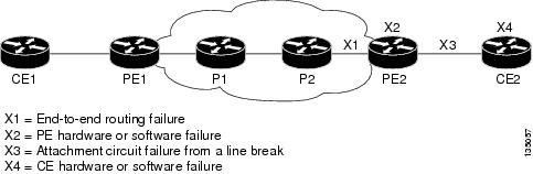
The L2VPN Pseudowire Redundancy feature provides the ability to ensure that the CE2 router in Figure 1 can always maintain network connectivity, even if one or all the failures in the figure occur.
The L2VPN Pseudowire Redundancy feature enables you to set up backup pseudowires. You can configure the network with redundant pseudowires (PWs) and redundant network elements, which are shown in Figure 2, Figure 3, and Figure 4.
Figure 2 shows a network with redundant pseudowires and redundant attachment circuits.
Figure 2 L2VPN Network with Redundant PWs and Attachment Circuits
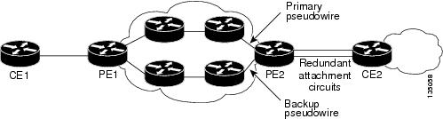
Figure 3 shows a network with redundant pseudowires, attachment circuits, and CE routers.
Figure 3 L2VPN Network with Redundant PWs, Attachment Circuits, and CE Routers
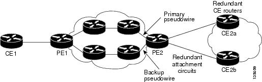
Figure 4 shows a network with redundant pseudowires, attachment circuits, CE routers, and PE routers.
Figure 4 L2VPN Network with Redundant PWs, Attachment Circuits, CE Routers,
and PE Routers

How to Configure L2VPN Pseudowire Redundancy
The L2VPN Pseudowire Redundancy feature enables you to configure a backup pseudowire in case the primary pseudowire fails. When the primary pseudowire fails, the PE router can switch to the backup pseudowire. You can have the primary pseudowire resume operation after it comes back up.
The default Label Distribution Protocol (LDP) session hold-down timer will enable the software to detect failures in about 180 seconds. That time can be configured so that the software can detect failures more quickly. See the mpls ldp holdtime command for more information.
The following sections explain how to configure the L2VPN Pseudowire Redundancy feature:
•![]() Configuring the Pseudowire (required)
Configuring the Pseudowire (required)
•![]() Configuring L2VPN Pseudowire Redundancy (required)
Configuring L2VPN Pseudowire Redundancy (required)
•![]() Xconnect as a Client of BFD (optional)
Xconnect as a Client of BFD (optional)
•![]() Forcing a Manual Switchover to the Backup Pseudowire VC (optional)
Forcing a Manual Switchover to the Backup Pseudowire VC (optional)
•![]() Verifying the L2VPN Pseudowire Redundancy Configuration (optional)
Verifying the L2VPN Pseudowire Redundancy Configuration (optional)
Configuring the Pseudowire
The successful transmission of the Layer 2 frames between PE routers is due to the configuration of the PE routers. You set up the connection, called a pseudowire, between the routers.
The pseudowire-class configuration group specifies the characteristics of the tunneling mechanism, which are:
•![]() Encapsulation type
Encapsulation type
•![]() Control protocol
Control protocol
•![]() Payload-specific options
Payload-specific options
You must specify the encapsulation mpls command as part of the pseudowire class for the AToM VCs to work properly. If you omit the encapsulation mpls command as part of the xconnect command, you receive the following error:
% Incomplete command.
Perform this task to configure a pseudowire class.
SUMMARY STEPS
1. ![]() enable
enable
2. ![]() configure terminal
configure terminal
3. ![]() pseudowire-class name
pseudowire-class name
4. ![]() encapsulation mpls
encapsulation mpls
5. ![]() interworking {ethernet | ip}
interworking {ethernet | ip}
DETAILED STEPS
Configuring L2VPN Pseudowire Redundancy
Use the following steps to configure the L2VPN Pseudowire Redundancy feature.
Prerequisites
For each transport type, the xconnect command is configured slightly differently. The following configuration steps use Ethernet VLAN over MPLS, which is configured in subinterface configuration mode. See Any Transport over MPLS to determine how to configure the xconnect command for other transport types.
SUMMARY STEPS
1. ![]() enable
enable
2. ![]() configure terminal
configure terminal
3. ![]() interface gigabitethernetslot/subslot/interface.subinterface
interface gigabitethernetslot/subslot/interface.subinterface
4. ![]() encapsulation dot1q vlan-id
encapsulation dot1q vlan-id
5. ![]() xconnect peer-router-id vcid {encapsulation mpls | pw-class pw-class-name}
xconnect peer-router-id vcid {encapsulation mpls | pw-class pw-class-name}
6. ![]() backup peer peer-router-ip-addr vcid [pw-class pw-class-name]
backup peer peer-router-ip-addr vcid [pw-class pw-class-name]
7. ![]() backup delay enable-delay {disable-delay | never}
backup delay enable-delay {disable-delay | never}
DETAILED STEPS
Xconnect as a Client of BFD
Redundant pseudowires are deployed to provide fault tolerance and resiliency to L2VPN-backhauled connections. The speed at which a system recovers from failures, especially when scaled to large numbers of pseudowires, is critical to many service providers and service level agreements (SLAs). The configuration of a trigger for redundant pseudowire switchover reduces the time that it takes a large number of pseudowires to failover. The configuration of this feature refers to a bidirectional forwarding detection (BFD) configuration, such as the following (the second URL in the bfd map command is the loopback URL in the monitor peer bfd command):
bfd-template multi-hop mh
interval min-tx 200 min-rx 200 multiplier 3 !
bfd map ipv4 10.1.1.0/24 10.1.1.1/32 mh
For more information about BFD configuration, see Bidirectional Forwarding Detection. A fundamental component of this capability is enabled by fast-failure detection (FFD).
Perform this task to configure a trigger for redundant pseudowire switchover.
SUMMARY STEPS
1. ![]() enable
enable
2. ![]() configure terminal
configure terminal
3. ![]() pseudowire-class mpls-ffd
pseudowire-class mpls-ffd
4. ![]() encapsulation mpls
encapsulation mpls
5. ![]() monitor peer bfd [local interface loopback-url]
monitor peer bfd [local interface loopback-url]
DETAILED STEPS
Forcing a Manual Switchover to the Backup Pseudowire VC
To force the router switch over to the backup or primary pseudowire, you can enter the xconnect backup force switchover command in privileged EXEC mode. You can specify either the interface of the primary attachment circuit (AC) to switch to or the IP-address and VC ID of the peer router.
A manual switchover can be made only if the interface or peer specified in the command is actually available and the xconnect will move to the fully active state when the command is entered.
SUMMARY STEPS
1. ![]() enable
enable
2. ![]() xconnect backup force-switchover interface {interface-info | peer ip-address vcid}
xconnect backup force-switchover interface {interface-info | peer ip-address vcid}
DETAILED STEPS
Verifying the L2VPN Pseudowire Redundancy Configuration
Use the following commands to verify that the L2VPN Pseudowire Redundancy feature is correctly configured.
SUMMARY STEPS
1. ![]() show mpls l2transport vc
show mpls l2transport vc
2. ![]() show mpls l2transport vc detail
show mpls l2transport vc detail
3. ![]() show xconnect all
show xconnect all
4. ![]() xconnect logging redundancy
xconnect logging redundancy
DETAILED STEPS
Step 1 ![]() show mpls l2transport vc
show mpls l2transport vc
In this example, the primary attachment circuit is up. The backup attachment circuit is available, but not currently selected. The show output displays as follows:
Router# show mpls l2transport vc
Local intf Local circuit Dest address VC ID Status
------------- ----------------------- --------------- ---------- ----------
Et0/0.1 Eth VLAN 101 10.0.0.2 101 UP
Et0/0.1 Eth VLAN 101 10.0.0.3 201 DOWN
Router# show mpls l2transport vc detail
Local interface: Et0/0.1 up, line protocol up, Eth VLAN 101 up
Destination address 10.0.0.2 VC ID: 101, VC status UP
.
.
.
Local interface: Et0/0.1 down, line protocol down, Eth VLAN 101 down
Destination address 10.0.0.3 VC ID: 201, VC status down
.
.
.
Step 2 ![]() show mpls l2transport vc detail
show mpls l2transport vc detail
In this example, the BFD monitoring for fast-failure detection is enabled:
Router# show mpls l2transport vc detail
Local interface: AT1/0/1 up, line protocol down, ATM AAL5 12/20 down
Destination address: 10.1.1.1, VC ID: 100, VC status: down
Output interface: Gi7/0/7, imposed label stack {18}
Preferred path: not configured
Default path: active
Next hop: 10.1.1.2
BFD monitoring is configured: session ID: ####
.
.
.
Step 3 ![]() show xconnect all
show xconnect all
In this example, the topology is Attachment Circuit 1 to Pseudowire 1 with a Pseudowire 2 as a backup:
Router# show xconnect all
Legend: XC ST=Xconnect State, S1=Segment1 State, S2=Segment2 State
UP=Up, DN=Down, AD=Admin Down, IA=Inactive, NH=No Hardware
XC ST Segment 1 S1 Segment 2 S2
------+---------------------------------+--+---------------------------------+--
UP pri ac Et0/0(Ethernet) UP mpls 10.55.55.2:1000 UP
IA sec ac Et0/0(Ethernet) UP mpls 10.55.55.3:1001 DN
In this example, the topology is Attachment Circuit 1 to Attachment Circuit 2 with a Pseudowire backup for Attachment Circuit 2:
Router# show xconnect all
Legend: XC ST=Xconnect State, S1=Segment1 State, S2=Segment2 State
UP=Up, DN=Down, AD=Admin Down, IA=Inactive, NH=No Hardware
XC ST Segment 1 S1 Segment 2 S2
------+---------------------------------+--+---------------------------------+--
UP pri ac Se6/0:150(FR DLCI) UP ac Se8/0:150(FR DLCI) UP
IA sec ac Se6/0:150(FR DLCI) UP mpls 10.55.55.3:7151 DN
Step 4 ![]() xconnect logging redundancy
xconnect logging redundancy
In addition to the show mpls l2transport vc command and the show xconnect command, you can use the xconnect logging redundancy command to track the status of the xconnect redundancy group:
Router(config)# xconnect logging redundancy
When this command is configured, the following messages will be generated during switchover events:
Activating the primary member:
00:01:07: %XCONNECT-5-REDUNDANCY: Activating primary member 10.55.55.2:1000
Activating the backup member:
00:01:05: %XCONNECT-5-REDUNDANCY: Activating secondary member 10.55.55.3:1001
Configuration Examples for L2VPN Pseudowire Redundancy
The following sections show the L2VPN Pseudowire Redundancy feature examples. These configuration examples show how the L2VPN Pseudowire Redundancy feature can be configured with the AToM (like-to-like), L2VPN Interworking, and Layer 2 Local Switching features.
•![]() Examples: L2VPN Pseudowire Redundancy and AToM (Like to Like)
Examples: L2VPN Pseudowire Redundancy and AToM (Like to Like)
•![]() Examples: L2VPN Pseudowire Redundancy and L2VPN Interworking
Examples: L2VPN Pseudowire Redundancy and L2VPN Interworking
•![]() Examples: L2VPN Pseudowire Redundancy with Layer 2 Local Switching
Examples: L2VPN Pseudowire Redundancy with Layer 2 Local Switching
Each of the configuration examples refers to one of the following pseudowire classes:
•![]() AToM (like-to-like) pseudowire class:
AToM (like-to-like) pseudowire class:
pseudowire-class mpls
encapsulation mpls
•![]() L2VPN IP interworking:
L2VPN IP interworking:
pseudowire-class mpls-ip
encapsulation mpls
interworking ip
Examples: L2VPN Pseudowire Redundancy and AToM (Like to Like)
The following example shows a High-Level Data Link Control (HDLC) attachment circuit xconnect with a backup pseudowire:
interface Serial4/0
xconnect 10.55.55.2 4000 pw-class mpls
backup peer 10.55.55.3 4001 pw-class mpls
The following example shows a Frame Relay attachment circuit xconnect with a backup pseudowire:
connect fr-fr-pw Serial6/0 225 l2transport
xconnect 10.55.55.2 5225 pw-class mpls
backup peer 10.55.55.3 5226 pw-class mpls
Examples: L2VPN Pseudowire Redundancy and L2VPN Interworking
The following example shows an Ethernet attachment circuit xconnect with L2VPN IP interworking and a backup pseudowire:
interface Ethernet0/0
xconnect 10.55.55.2 1000 pw-class mpls-ip
backup peer 10.55.55.3 1001 pw-class mpls-ip
The following example shows an Ethernet VLAN attachment circuit xconnect with L2VPN IP interworking and a backup pseudowire:
interface Ethernet1/0.1
encapsulation dot1Q 200
no ip directed-broadcast
xconnect 10.55.55.2 5200 pw-class mpls-ip
backup peer 10.55.55.3 5201 pw-class mpls-ip
The following example shows a Frame Relay attachment circuit xconnect with L2VPN IP interworking and a backup pseudowire:
connect fr-ppp-pw Serial6/0 250 l2transport
xconnect 10.55.55.2 8250 pw-class mpls-ip
backup peer 10.55.55.3 8251 pw-class mpls-ip
The following example shows a PPP attachment circuit xconnect with L2VPN IP interworking and a backup pseudowire:
interface Serial7/0
encapsulation ppp
xconnect 10.55.55.2 2175 pw-class mpls-ip
backup peer 10.55.55.3 2176 pw-class mpls-ip
Examples: L2VPN Pseudowire Redundancy with Layer 2 Local Switching
The following example shows an Ethernet VLAN-VLAN local switching xconnect with a pseudowire backup for Ethernet segment E2/0.2. If the subinterface associated with E2/0.2 goes down, the backup pseudowire is activated.
connect vlan-vlan Ethernet1/0.2 Ethernet2/0.2
backup peer 10.55.55.3 1101 pw-class mpls
The following example shows a Frame Relay-to-Frame Relay local switching connect with a pseudowire backup for Frame Relay segment S8/0 150. If data-link connection identifier (DLCI) 150 on S8/0 goes down, the backup pseudowire is activated.
connect fr-fr-ls Serial6/0 150 Serial8/0 150
backup peer 10.55.55.3 7151 pw-class mpls
Additional References
Related Documents
|
|
|
|---|---|
Cisco IOS commands |
|
MPLS commands |
|
Any transport over MPLS |
|
High availability for AToM |
|
L2VPN interworking |
|
Layer 2 local switching |
|
PWE3 MIB |
Pseudowire Emulation Edge-to-Edge MIBs for Ethernet and Frame Relay Services |
Packet sequencing |
|
Information about BFD |
Standard
|
|
|
|---|---|
None |
— |
MIB
|
|
|
|---|---|
None |
To locate and download MIBs for selected platforms, Cisco software releases, and feature sets, use Cisco MIB Locator found at the following URL: |
RFC
|
|
|
|---|---|
None |
— |
Technical Assistance
Feature Information for L2VPN Pseudowire Redundancy
Table 1 lists the features in this module and provides links to specific configuration information.
Use Cisco Feature Navigator to find information about platform support and software image support. Cisco Feature Navigator enables you to determine which Cisco IOS and Catalyst OS software images support a specific software release, feature set, or platform. To access Cisco Feature Navigator, go to http://www.cisco.com/go/cfn. An account on Cisco.com is not required.

Note ![]() Table 1 lists only the software release that introduced support for a given feature in a given software release train. Unless noted otherwise, subsequent releases of that software release train also support that feature.
Table 1 lists only the software release that introduced support for a given feature in a given software release train. Unless noted otherwise, subsequent releases of that software release train also support that feature.
 Feedback