-
- MPLS Traffic Engineering - LSP Attributes
- MPLS Traffic Engineering (TE) - Autotunnel Primary and Backup
- MPLS Traffic Engineering - AutoTunnel Mesh Groups
- MPLS Traffic Engineering - Verbatim Path Support
- MPLS Traffic Engineering - RSVP Hello State Timer
- MPLS Traffic Engineering Forwarding Adjacency
- MPLS Traffic Engineering (TE) - Class-based Tunnel Selection
- MPLS Traffic Engineering - Interarea Tunnels
- MPLS TE - Bundled Interface Support
- MPLS Traffic Engineering�Automatic Bandwidth Adjustment for TE Tunnels
- MPLS Point-to-Multipoint Traffic Engineering
- MPLS Traffic Engineering�Tunnel Source
-
- MPLS Traffic Engineering - Inter-AS TE
- MPLS Traffic Engineering - Shared Risk Link Groups
- MPLS Traffic Engineering (TE) - Autotunnel Primary and Backup
- MPLS Traffic Engineering (TE) - Path Protection
- MPLS Traffic Engineering (TE) - Fast Reroute (FRR) Link and Node Protection
- MPLS TE: Link and Node Protection, with RSVP Hellos Support (with Fast Tunnel Interface Down Detection)
- MPLS Traffic Engineering: BFD-triggered Fast Reroute (FRR)
-
- MPLS MTU Command Changes
- AToM Static Pseudowire Provisioning
- MPLS Pseudowire Status Signaling
- L2VPN Interworking
- L2VPN Pseudowire Redundancy
- L2VPN Pseudowire Switching
- VPLS Autodiscovery: BGP Based
- H-VPLS N-PE Redundancy for QinQ and MPLS Access
- L2VPN Multisegment Pseudowires
- QOS Policy Support on L2VPN ATM PVPs
- L2VPN: Pseudowire Preferential Forwarding
-
- Configuring MPLS Layer 3 VPNs
- MPLS VPN Half-Duplex VRF
- MPLS VPN�Show Running VRF
- MPLS VPN�VRF CLI for IPv4 and IPv6 VPNs
- MPLS VPN--BGP Local Convergence
- MPLS VPN�Route Target Rewrite
- MPLS VPN�Per VRF Label
- MPLS VPN 6VPE per VRF Label
- MPLS Multi-VRF (VRF Lite) Support
- BGP Best External
- BGP PIC Edge for IP and MPLS-VPN
- MPLS VPN - L3VPN over GRE
- Dynamic Layer-3 VPNs with Multipoint GRE Tunnels
- MPLS VPN over mGRE
-
- MPLS LSP Ping/Traceroute for LDP/TE, and LSP Ping for VCCV
- MPLS EM�MPLS LSP Multipath Tree Trace
- Pseudowire Emulation Edge-to-Edge MIBs for Ethernet, Frame Relay, and ATM Services
- MPLS Enhancements to Interfaces MIB
- MPLS Label Distribution Protocol MIB Version 8 Upgrade
- MPLS EM�MPLS LDP MIB - RFC 3815
- MPLS Label Switching Router MIB
- MPLS EM�MPLS LSR MIB - RFC 3813
- MPLS Traffic Engineering MIB
- MPLS Traffic Engineering - Fast Reroute MIB
- MPLS EM - TE MIB RFC 3812
- MPLS VPN�MIB Support
- MPLS EM - MPLS VPN MIB RFC4382 Upgrade
-
- MPLS High Availability: Overview
- MPLS High Availability: Command Changes
- MPLS LDP Graceful Restart
- NSF/SSO - MPLS LDP and LDP Graceful Restart
- NSF/SSO: MPLS VPN
- AToM Graceful Restart
- NSF/SSO�Any Transport over MPLS and AToM Graceful Restart
- NSF/SSO - MPLS TE and RSVP Graceful Restart
- ISSU MPLS Clients
- NSF/SSO/ISSU Support for VPLS
- NSF/SSO and ISSU - MPLS VPN 6VPE and 6PE
Cisco IOS Multiprotocol Label Switching Configuration Guide, Release 12.2SR
Bias-Free Language
The documentation set for this product strives to use bias-free language. For the purposes of this documentation set, bias-free is defined as language that does not imply discrimination based on age, disability, gender, racial identity, ethnic identity, sexual orientation, socioeconomic status, and intersectionality. Exceptions may be present in the documentation due to language that is hardcoded in the user interfaces of the product software, language used based on RFP documentation, or language that is used by a referenced third-party product. Learn more about how Cisco is using Inclusive Language.
- Updated:
- February 12, 2008
Chapter: MPLS EM—MPLS LDP MIB - RFC 3815
- Finding Feature Information
- Contents
- Prerequisites for MPLS EM—MPLS LDP MIB - RFC 3815
- Restrictions for MPLS EM—MPLS LDP MIB - RFC 3815
- Information About MPLS EM—MPLS LDP MIB - RFC 3815
- Label Distribution Protocol Overview
- MPLS EM—MPLS LDP MIB - RFC 3815 Feature Design and Use
- Benefits of Using the MPLS EM—MPLS LDP MIB - RFC 3815 Feature
- MPLS LDP MIB (RFC 3815) Elements
- Events Generating MPLS LDP MIB Notifications
- Scalar Objects in the MPLS LDP MIB Modules (RFC 3815)
- MIB Tables in the MPLS-LDP-STD-MIB Module (RFC 3815)
- MPLS LDP Entity Table (mplsLdpEntityTable) Objects and Descriptions
- MPLS LDP Entity Statistics Table (mplsLdpEntityStatsTable) Objects and Descriptions
- MPLS LDP Peer Table (mplsLdpPeerTable) Objects and Descriptions
- MPLS LDP Session Table (mplsLdpSessionTable) Objects and Descriptions
- MPLS LDP Session Statistics Table (mplsLdpSessionStatsTable) Objects and Descriptions
- MPLS LDP Hello Adjacency Table (mplsLdpHelloAdjacencyTable) Objects and Descriptions
- MIB Tables in the MPLS-LDP-ATM-STD-MIB Module (RFC 3815)
- MIB Table in the MPLS-LDP-GENERIC-STD-MIB Module (RFC 3815)
- VPN Contexts in the MPLS LDP MIB
- Differences Between the MPLS-LDP-STD-MIB and the MPLS-LDP-MIB
- Differences Between the MPLS-LDP-MIB and the MPLS-LDP-ATM-STD-MIB (RFC 3815)
- Differences Between the MPLS-LDP-MIB and the MPLS-LDP-GENERIC-STD-MIB (RFC 3815)
- How to Configure SNMP for MPLS EM—MPLS LDP MIB - RFC 3815
MPLS EM—MPLS LDP MIB—RFC 3815
The MPLS EM—MPLS LDP MIB - RFC 3815 feature document describes the MIBs that support the Multiprotocol Label Switching (MPLS) Label Distribution Protocol (LDP) based on RFC 3815, Definitions of Managed Objects for the Multiprotocol Label Switching (MPLS), Label Distribution Protocol (LDP), and describes the differences between RFC 3815 and the MPLS-LDP-MIB based on the Internet Engineering Task Force (IETF) draft Version 8 (draft-ieft-mpls-ldp-08.txt). RFC 3815 and IETF draft Version 8 provide an interface for managing LDP through the use of the Simple Network Management Protocol (SNMP).
In RFC 3815, the content of the MPLS-LDP-MIB is divided into four MIB modules: the MPLS-LDP-STD-MIB, the MPLS-LDP-ATM-STD-MIB, the MPLS-LDP-FRAME-RELAY-STD-MIB, and the MPLS-LDP-GENERIC-STD-MIB.
Cisco IOS MPLS Embedded Management (EM) is a set of standards and value-added services that facilitate the deployment, operation, administration, and management of MPLS-based networks in line with the fault, configuration, accounting, performance, and security (FCAPS) model.
Finding Feature Information
Your software release may not support all the features documented in this module. For the latest feature information and caveats, see the release notes for your platform and software release. To find information about the features documented in this module, and to see a list of the releases in which each feature is supported, see the "Feature Information for MPLS EM—MPLS LDP MIB - RFC 3815" section.
Use Cisco Feature Navigator to find information about platform support and Cisco IOS and Catalyst OS software image support. To access Cisco Feature Navigator, go to http://www.cisco.com/go/cfn. An account on Cisco.com is not required.
Contents
•![]() Prerequisites for MPLS EM—MPLS LDP MIB - RFC 3815
Prerequisites for MPLS EM—MPLS LDP MIB - RFC 3815
•![]() Restrictions for MPLS EM—MPLS LDP MIB - RFC 3815
Restrictions for MPLS EM—MPLS LDP MIB - RFC 3815
•![]() Information About MPLS EM—MPLS LDP MIB - RFC 3815
Information About MPLS EM—MPLS LDP MIB - RFC 3815
•![]() How to Configure SNMP for MPLS EM—MPLS LDP MIB - RFC 3815
How to Configure SNMP for MPLS EM—MPLS LDP MIB - RFC 3815
•![]() Configuration Examples for MPLS EM—MPLS LDP MIB - RFC 3815
Configuration Examples for MPLS EM—MPLS LDP MIB - RFC 3815
•![]() Feature Information for MPLS EM—MPLS LDP MIB - RFC 3815
Feature Information for MPLS EM—MPLS LDP MIB - RFC 3815
•![]() Feature Information for MPLS EM—MPLS LDP MIB - RFC 3815
Feature Information for MPLS EM—MPLS LDP MIB - RFC 3815
Prerequisites for MPLS EM—MPLS LDP MIB - RFC 3815
•![]() SNMP must be installed and enabled on the label switch routers (LSRs) or label edge routers (LERs).
SNMP must be installed and enabled on the label switch routers (LSRs) or label edge routers (LERs).
•![]() MPLS must be enabled on the LSRs or LERs.
MPLS must be enabled on the LSRs or LERs.
•![]() LDP must be enabled on the LSRs or LERs.
LDP must be enabled on the LSRs or LERs.
•![]() Cisco Express Forwarding must be enabled on the LSRs or LERs.
Cisco Express Forwarding must be enabled on the LSRs or LERs.
For where to find configuration information for MPLS and LDP, see the "Related Documents" section.
Restrictions for MPLS EM—MPLS LDP MIB - RFC 3815
The implementation of the MPLS LDP MIB (RFC 3815) for Cisco IOS Release12.2(33)SRB is limited to read-only (RO) permission for MIB objects.
The following MPLS-LDP-STD-MIB tables are not implemented for Cisco IOS Release 12.2(33)SRB:
•![]() mplsInSegmentLdpLspTable
mplsInSegmentLdpLspTable
•![]() mplsOutSegmentLdpLspTable
mplsOutSegmentLdpLspTable
•![]() mplsFecTable
mplsFecTable
•![]() mplsLdpLspFecTable
mplsLdpLspFecTable
•![]() mplsLdpSessionPeerAddrTable
mplsLdpSessionPeerAddrTable
The following MPLS-LDP-FRAME-RELAY-STD-MIB tables are not implemented for Cisco IOS Release 12.2(33)SRB:
•![]() mplsLdpEntityFrameRelayTable
mplsLdpEntityFrameRelayTable
•![]() mplsLdpEntityFrameRelayLRTable
mplsLdpEntityFrameRelayLRTable
•![]() mplsLdpFrameRelaySessionTable
mplsLdpFrameRelaySessionTable
Information About MPLS EM—MPLS LDP MIB - RFC 3815
Before you configure SNMP for the MPLS EM—MPLS LDP MIB - RFC 3815 feature you should understand the following concepts:
•![]() Label Distribution Protocol Overview
Label Distribution Protocol Overview
•![]() MPLS EM—MPLS LDP MIB - RFC 3815 Feature Design and Use
MPLS EM—MPLS LDP MIB - RFC 3815 Feature Design and Use
•![]() Benefits of Using the MPLS EM—MPLS LDP MIB - RFC 3815 Feature
Benefits of Using the MPLS EM—MPLS LDP MIB - RFC 3815 Feature
•![]() MPLS LDP MIB (RFC 3815) Elements
MPLS LDP MIB (RFC 3815) Elements
•![]() Events Generating MPLS LDP MIB Notifications
Events Generating MPLS LDP MIB Notifications
•![]() Scalar Objects in the MPLS LDP MIB Modules (RFC 3815)
Scalar Objects in the MPLS LDP MIB Modules (RFC 3815)
•![]() MIB Tables in the MPLS-LDP-STD-MIB Module (RFC 3815)
MIB Tables in the MPLS-LDP-STD-MIB Module (RFC 3815)
•![]() MIB Tables in the MPLS-LDP-ATM-STD-MIB Module (RFC 3815)
MIB Tables in the MPLS-LDP-ATM-STD-MIB Module (RFC 3815)
•![]() MIB Table in the MPLS-LDP-GENERIC-STD-MIB Module (RFC 3815)
MIB Table in the MPLS-LDP-GENERIC-STD-MIB Module (RFC 3815)
•![]() VPN Contexts in the MPLS LDP MIB
VPN Contexts in the MPLS LDP MIB
•![]() Differences Between the MPLS-LDP-STD-MIB and the MPLS-LDP-MIB
Differences Between the MPLS-LDP-STD-MIB and the MPLS-LDP-MIB
•![]() Differences Between the MPLS-LDP-MIB and the MPLS-LDP-ATM-STD-MIB (RFC 3815)
Differences Between the MPLS-LDP-MIB and the MPLS-LDP-ATM-STD-MIB (RFC 3815)
•![]() Differences Between the MPLS-LDP-MIB and the MPLS-LDP-GENERIC-STD-MIB (RFC 3815)
Differences Between the MPLS-LDP-MIB and the MPLS-LDP-GENERIC-STD-MIB (RFC 3815)
Label Distribution Protocol Overview
MPLS is a packet forwarding technology that uses a short, fixed-length value called a label in packets to determine the next hop for packet transport through an MPLS network by means of LSRs.
A fundamental MPLS principle is that LSRs in an MPLS network must agree on the definition of the labels being used for packet forwarding operations. Label agreement is achieved in an MPLS network by means of procedures defined in the Label Distribution Protocol (LDP).
LDP operations begin with a discovery (hello) process, during which an LDP entity (a local LSR) finds a cooperating LDP peer in the network and negotiates basic operating procedures between them. The recognition and identification of a peer by means of this discovery process results in a hello adjacency, which represents the context within which label binding information is exchanged between the local LSR and its LDP peer. An LDP function then creates an active LDP session between the two LSRs to effect the exchange of label binding information. The result of this process, when carried to completion with respect to all the LSRs in an MPLS network, is a label switched path (LSP), which constitutes an end-to-end packet transmission pathway between the communicating network devices.
LSRs use LDP to collect, distribute, and label binding information to other LSRs in an MPLS network, thereby enabling the hop-by-hop forwarding of packets in the network along normally routed paths.
MPLS EM—MPLS LDP MIB - RFC 3815 Feature Design and Use
RFC 3815 defines four MIB modules to support the configuration and monitoring of LDP. The MPLS-LDP-STD-MIB module defines objects that are common to all LDP implementations. To monitor LDP on an LSR or an LER, you need to use this MIB and one of the following Layer 2 MIB modules:
•![]() MPLS-LDP-GENERIC-STD-MIB—Use this module and the MPLS-LDP-STD-MIB if the LSR or LER supports LDP that uses the global label space; for example, for Layer 2 Ethernet. This module defines Layer 2 per platform label space objects.
MPLS-LDP-GENERIC-STD-MIB—Use this module and the MPLS-LDP-STD-MIB if the LSR or LER supports LDP that uses the global label space; for example, for Layer 2 Ethernet. This module defines Layer 2 per platform label space objects.
•![]() MPLS-LDP-ATM-STD-MIB—Use this module and the MPLS-LDP-STD-MIB if the LSR or LER supports LDP that uses Layer 2 ATM. This module defines Layer 2 ATM objects.
MPLS-LDP-ATM-STD-MIB—Use this module and the MPLS-LDP-STD-MIB if the LSR or LER supports LDP that uses Layer 2 ATM. This module defines Layer 2 ATM objects.
•![]() MPLS-LDP-FRAME-RELAY-STD-MIB—Use this module and the MPLS-LDP-STD-MIB if the LSR or LER supports LDP that uses Layer 2 Frame Relay. This module defines Layer 2 Frame Relay objects.
MPLS-LDP-FRAME-RELAY-STD-MIB—Use this module and the MPLS-LDP-STD-MIB if the LSR or LER supports LDP that uses Layer 2 Frame Relay. This module defines Layer 2 Frame Relay objects.

Note ![]() The MPLS-LDP-FRAME-RELAY-STD-MIB is not implemented for Cisco IOS Release 12.2(33)SRA.
The MPLS-LDP-FRAME-RELAY-STD-MIB is not implemented for Cisco IOS Release 12.2(33)SRA.
If the LSR or LER uses LDP that supports Ethernet, ATM, and Frame Relay, then all four MIB modules need to be used by an SNMP agent on the LSR or LER.
The RFC 3815 upgrade to the MPLS-LDP-MIB is implemented to enable standard, SNMP-based network management of the label switching features in Cisco IOS software. Providing this capability requires SNMP agent code to execute on a designated network management station (NMS) in the network. The NMS serves as the medium for user interaction with the network management objects in the MIB.
The SNMP agent is a layered structure that is compatible with Cisco IOS software and presents a network administrative and management interface to the objects in the MPLS LDP MIB and, adds to the rich set of label switching capabilities supported by the Cisco IOS software.
You can use an SNMP agent to access MIB module objects using standard SNMP get and getnext commands to accomplish a variety of network management tasks. All the objects in the MPLS LDP MIB modules follow the conventions defined in RFC 3815, which defines network management objects in a structured and standardized manner.
Slight differences that exist between the RFC 3815 and the implementation of equivalent functions in the Cisco IOS software require some minor translations between the MPLS LDP MIB objects and the internal data structures of Cisco IOS software. Such translations are accomplished by the SNMP agent, which runs in the background on the NMS workstation as a low priority process.
Cisco IOS Release 12(33)SRB supports the following MPLS LDP MIB-related functions:
•![]() Generating and sending of event notification messages that signal changes in the status of LDP sessions
Generating and sending of event notification messages that signal changes in the status of LDP sessions
•![]() Enabling and disabling of event notification messages by means of extensions to existing SNMP command-line interface (CLI) commands
Enabling and disabling of event notification messages by means of extensions to existing SNMP command-line interface (CLI) commands
•![]() Specification of the name or the IP address of an NMS workstation in the operating environment to which Cisco IOS event notification messages are to be sent to serve network administrative and management purposes
Specification of the name or the IP address of an NMS workstation in the operating environment to which Cisco IOS event notification messages are to be sent to serve network administrative and management purposes
•![]() Storage of the configuration pertaining to an event notification message in NVRAM of the NMS
Storage of the configuration pertaining to an event notification message in NVRAM of the NMS
The structure of the MPLS LDP MIBs conforms to Abstract Syntax Notation One (ASN.1), thereby forming a highly structured and idealized database of network management objects.
MIB structure is represented by a tree hierarchy. Branches along the tree have short text strings and integers to identify them. Text strings describe object names, and integers allow computer software to encode compact representations of the names.
The MPLS LDP MIB is located on the branch of the Internet MIB hierarchy represented by the object identifier 1.3.6.1.2.1.10.166. This branch can also be represented by its object name iso.org.dod.internet.mgmt.mib-2.transmission.mplsStdMIB. The MPLS-LSR-STD-MIB is identified by the object name mplsLsrStdMIB, which is denoted by the number 4. Therefore, objects in the MPLS-LDP-STD-MIB can be identified in either of the following ways:
•![]() The object identifier—1.3.6.1.2.1.10.166.4.[MIB-variable]
The object identifier—1.3.6.1.2.1.10.166.4.[MIB-variable]
•![]() The object name— iso.org.dod.internet.mgmt.mib-2.transmission.mplsStdMIB.mplsLdpStdMIB.[MIB-variable]
The object name— iso.org.dod.internet.mgmt.mib-2.transmission.mplsStdMIB.mplsLdpStdMIB.[MIB-variable]
You can use any standard SNMP application to retrieve and display information from the MPLS LDP MIBs by means of standard SNMP GET operations. Similarly, you can traverse and display information in the MIB by means of SNMP GETNEXT operations.
Benefits of Using the MPLS EM—MPLS LDP MIB - RFC 3815 Feature
The MPLS LDP MIBs (RFC 3815) provide the following benefits:
•![]() Retrieves MIB parameters relating to the operation of LDP entities, such as:
Retrieves MIB parameters relating to the operation of LDP entities, such as:
–![]() Well-known LDP discovery port
Well-known LDP discovery port
–![]() Maximum transmission unit (MTU)
Maximum transmission unit (MTU)
–![]() Proposed keepalive timer interval
Proposed keepalive timer interval
–![]() Loop detection
Loop detection
–![]() Session establishment thresholds
Session establishment thresholds
–![]() Range of Virtual Path Identifier (VPI)-Virtual Channel Identifier (VCI) pairs to be used in forming labels
Range of Virtual Path Identifier (VPI)-Virtual Channel Identifier (VCI) pairs to be used in forming labels
•![]() Gathers statistics relating to LDP operations, such as:
Gathers statistics relating to LDP operations, such as:
–![]() Count of the total established sessions for an LDP entity
Count of the total established sessions for an LDP entity
–![]() Count of the total attempted sessions for an LDP entity
Count of the total attempted sessions for an LDP entity
•![]() Monitors the time remaining for hello adjacencies
Monitors the time remaining for hello adjacencies
•![]() Monitors the characteristics and status of LDP peers, such as:
Monitors the characteristics and status of LDP peers, such as:
–![]() Internetwork layer address of LDP peers
Internetwork layer address of LDP peers
–![]() Loop detection of LDP peers
Loop detection of LDP peers
–![]() Default MTU of the LDP peer
Default MTU of the LDP peer
–![]() Number of seconds the LDP peer proposes as the value of the keepalive interval
Number of seconds the LDP peer proposes as the value of the keepalive interval
•![]() Monitors the characteristics and status of LDP sessions, such as:
Monitors the characteristics and status of LDP sessions, such as:
–![]() Displaying the error counters
Displaying the error counters
–![]() Determining the LDP version being used by the LDP session
Determining the LDP version being used by the LDP session
–![]() Determining the keepalive hold time remaining for an LDP session
Determining the keepalive hold time remaining for an LDP session
–![]() Determining the state of an LDP session (whether the session is active)
Determining the state of an LDP session (whether the session is active)
–![]() Determining the label ranges for platform-wide and interface-specific sessions
Determining the label ranges for platform-wide and interface-specific sessions
–![]() Determining the ATM parameters
Determining the ATM parameters
MPLS LDP MIB (RFC 3815) Elements
The following functional elements of the MPLS LDP MIBs (RFC 3815) are used to perform LDP operations:
•![]() LDP entity—Refers to an instance of LDP for purposes of exchanging label spaces; describes a potential session.
LDP entity—Refers to an instance of LDP for purposes of exchanging label spaces; describes a potential session.
•![]() LDP peer—Refers to a remote LDP entity (that is, a nonlocal LSR).
LDP peer—Refers to a remote LDP entity (that is, a nonlocal LSR).
•![]() LDP session—Refers to an active LDP process between a local LSR and a remote LDP peer.
LDP session—Refers to an active LDP process between a local LSR and a remote LDP peer.
•![]() Hello adjacency—Refers to the result of an LDP discovery process that affirms the state of two LSRs in an MPLS network as being adjacent to each other (that is, as being LDP peers). When the neighbor is discovered, the neighbor becomes a hello adjacency. An LDP session can be established with the hello adjacency. After the session is established, label bindings can be exchanged between the LSRs.
Hello adjacency—Refers to the result of an LDP discovery process that affirms the state of two LSRs in an MPLS network as being adjacent to each other (that is, as being LDP peers). When the neighbor is discovered, the neighbor becomes a hello adjacency. An LDP session can be established with the hello adjacency. After the session is established, label bindings can be exchanged between the LSRs.
These MPLS LDP MIB elements are briefly described in the following sections:
In effect, the MPLS LDP MIBs provide a network management database that supports real-time access to the various MIB objects within, describing the current state of MPLS LDP operations in the network. This network management information database is accessible by means of standard SNMP commands issued from an NMS in the MPLS LDP operating environment.
The MPLS LDP MIBs support the following network management and administrative activities:
•![]() Retrieving MPLS LDP MIB parameters pertaining to LDP operations
Retrieving MPLS LDP MIB parameters pertaining to LDP operations
•![]() Monitoring the characteristics and the status of LDP peers
Monitoring the characteristics and the status of LDP peers
•![]() Monitoring the status of LDP sessions between LDP peers
Monitoring the status of LDP sessions between LDP peers
•![]() Monitoring hello adjacencies in the network
Monitoring hello adjacencies in the network
•![]() Gathering statistics regarding LDP sessions
Gathering statistics regarding LDP sessions
LDP Entities
An LDP entity is uniquely identified by an LDP identifier that consists of the mplsLdpEntityLdpId and the mplsLdpEntityIndex (see Figure 1) objects:
•![]() The mplsLdpEntityLdpId consists of the local LSR ID (four octets) and the label space ID (two octets). The label space ID identifies a specific label space available within the LSR.
The mplsLdpEntityLdpId consists of the local LSR ID (four octets) and the label space ID (two octets). The label space ID identifies a specific label space available within the LSR.
•![]() The mplsLdpEntityIndex consists of the IP address of the peer active hello adjacency, which is the 32-bit representation of the IP address assigned to the peer LSR.
The mplsLdpEntityIndex consists of the IP address of the peer active hello adjacency, which is the 32-bit representation of the IP address assigned to the peer LSR.
The mplsLdpEntityProtocolVersion is a sample object from the mplsLdpEntityTable.
Figure 1 shows the following indexing:
•![]() mplsLdpEntityLdpId = 10.10.10.10.0.0
mplsLdpEntityLdpId = 10.10.10.10.0.0
•![]() LSR ID = 10.10.10.10
LSR ID = 10.10.10.10
•![]() Label space ID = 0.0
Label space ID = 0.0
Note ![]() The mplsLdpEntityLdpId or the LDP ID consists of the LSR ID and the label space ID.
The mplsLdpEntityLdpId or the LDP ID consists of the LSR ID and the label space ID.
•![]() The IP address of peer active hello adjacency or the mplsLdpEntityIndex = 3232235777, which is the 32-bit representation of the IP address assigned to the peer's active hello adjacency.
The IP address of peer active hello adjacency or the mplsLdpEntityIndex = 3232235777, which is the 32-bit representation of the IP address assigned to the peer's active hello adjacency.
Figure 1 Sample Indexing for an LDP Entity

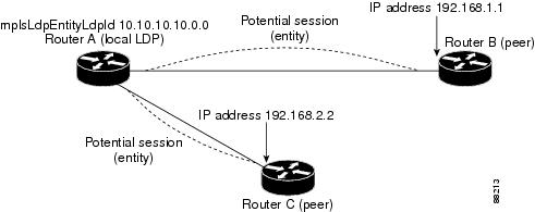
An LDP entity represents a label space that has the potential for a session with an LDP peer. An LDP entity is configured when a hello adjacency receives a hello message from an LDP peer.
In Figure 2, Router A has potential sessions with two remote peers, Routers B and C. The mplsLdpEntityLdpId is 10.10.10.10.0.0, and the IP address of the peer active hello adjacency (mplsLdpEntityIndex) is 3232235777, which is the 32-bit representation of the IP address 192.168.1.1 for Router B.
Figure 2 LDP Entity
LDP Sessions and Peers
LDP sessions exist between local entities and remote peers for the purpose of distributing label bindings. There is always a one-to-one correspondence between an LDP peer and an LDP session. A single LDP session is an LDP instance that communicates across one or more network links with a single LDP peer.
LDP supports the following types of sessions:
•![]() Interface-specific—An interface-specific session uses interface resources for label space distributions. For example, each label-controlled ATM (LC-ATM) interface uses its own VPIs and VCIs for label space distributions. Depending on its configuration, an LDP platform can support zero, one, or more interface-specific sessions. Each LC-ATM interface has its own interface-specific label space and a nonzero label space ID.
Interface-specific—An interface-specific session uses interface resources for label space distributions. For example, each label-controlled ATM (LC-ATM) interface uses its own VPIs and VCIs for label space distributions. Depending on its configuration, an LDP platform can support zero, one, or more interface-specific sessions. Each LC-ATM interface has its own interface-specific label space and a nonzero label space ID.
•![]() Platform-wide—An LDP platform supports a single platform-wide session for use by all interfaces that can share the same global label space. For Cisco platforms, all interface types except LC-ATM use the platform-wide session and have a label space ID of zero.
Platform-wide—An LDP platform supports a single platform-wide session for use by all interfaces that can share the same global label space. For Cisco platforms, all interface types except LC-ATM use the platform-wide session and have a label space ID of zero.
When a session is established between two peers, entries are created in the mplsLdpPeerTable and the mplsLdpSessionTable because they have the same indexing.
In Figure 3, Router A has two remote peers, Routers B and C. Router A has a single platform-wide session that consists of two serial interfaces with Router B and another platform-wide session with Router C. Router A also has two interface-specific sessions with Router B.
Figure 3 LDP Sessions
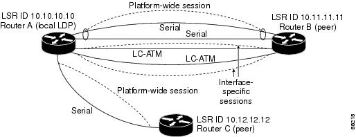
Figure 4 shows entries that correspond to the mplsLdpPeerTable and the mplsLdpSessionTable in Figure 3.
In Figure 4, mplsLdpSesState is a sample object from the mplsLdpSessionTable on Router A. Four mplsLdpSesState sample objects are shown (top to bottom). The first object represents a platform-wide session associated with two serial interfaces. The next two objects represent interface-specific sessions for the LC-ATM interfaces on Routers A and B. These interface-specific sessions have nonzero peer label space IDs. The last object represents a platform-wide session for the next peer, Router C.
The indexing is based on the entries in the mplsLdpEntityTable. It begins with the indexes of the mplsLdpEntityTable and adds the following:
•![]() Peer LDP ID = 10.11.11.11.0.0
Peer LDP ID = 10.11.11.11.0.0
The peer LDP ID consists of the peer LSR ID (four octets) and the peer label space ID (two octets).
•![]() Peer LSR ID = 10.11.11.11
Peer LSR ID = 10.11.11.11
•![]() Peer label space ID = 0.0
Peer label space ID = 0.0
The peer label space ID identifies a specific peer label space available within the LSR.
Figure 4 Sample Indexing for an LDP Session

LDP Hello Adjacencies
An LDP hello adjacency is an association between a remotely discovered LDP process and a specific network path to reach the remote LDP process. An LDP hello adjacency enables two adjacent peers to exchange label binding information.
An LDP hello adjacency exists for each link on which LDP runs. Multiple LDP hello adjacencies exist whenever there is more than one link in a session between a router and its peer, such as in a platform-wide session.
A hello adjacency is considered active if it is currently engaged in a session, or nonactive if it is not currently engaged in a session.
A targeted hello adjacency is not directly connected to its peer and has an unlimited number of hops between itself and its peer. A linked hello adjacency is directly connected between two routers.
In Figure 5, Router A has two remote peers, Routers B and C. Router A has a platform-wide session with Router B that consists of three serial interfaces, one of which is active and another platform-wide (targeted) session with Router C.
Figure 5 Hello Adjacency

Figure 6 shows entries in the mplsLdpHelloAdjacencyTable. There are four
mplsLdpHelloAdjHoldTime sample objects (top to bottom). They represent the two platform-wide sessions and the four serial links shown in Figure 5.
The indexing is based on the mplsLdpSessionTable. When the mplsLdpHelloAdjIndex enumerates the different links within a single session, the active link is mplsLdpHelloAdjIndex = 1.
Figure 6 Sample Indexing for an LDP Hello Adjacency

Events Generating MPLS LDP MIB Notifications
When you enable MPLS LDP MIB notification functionality by issuing the snmp-server enable traps mpls rfc ldp command, notification messages are generated and sent to a designated NMS in the network to signal the occurrence of specific events within Cisco IOS software.
The MPLS LDP MIB objects that announce LDP status transitions and event notifications are the following:
•![]() mplsLdpSessionUp—This message is generated when an LDP entity (a local LSR) establishes an LDP session with another LDP entity (an adjacent LDP peer in the network). Enable this notification with the session-up keyword.
mplsLdpSessionUp—This message is generated when an LDP entity (a local LSR) establishes an LDP session with another LDP entity (an adjacent LDP peer in the network). Enable this notification with the session-up keyword.
•![]() mplsLdpSessionDown—This message is generated when an LDP session between a local LSR and its adjacent LDP peer is terminated. Enable this notification with the session-down keyword.
mplsLdpSessionDown—This message is generated when an LDP session between a local LSR and its adjacent LDP peer is terminated. Enable this notification with the session-down keyword.
The up and down notifications indicate the last active interface in the LDP session.
•![]() mplsLdpPathVectorLimitMismatch—This message is generated when a local LSR establishes an LDP session with its adjacent peer LSR, but the two LSRs have dissimilar path vector limits. Enable this notification with the pv-limit keyword.
mplsLdpPathVectorLimitMismatch—This message is generated when a local LSR establishes an LDP session with its adjacent peer LSR, but the two LSRs have dissimilar path vector limits. Enable this notification with the pv-limit keyword.
The value of the path vector limit can range from 0 to 255; a value of 0 indicates that loop detection is off; any value other than 0 up to 255 indicates that loop detection is on and, in addition, specifies the maximum number of hops through which an LDP message can pass before a loop condition in the network is sensed.
We recommend that all LDP-enabled routers in the network be configured with the same path vector limit. Accordingly, the mplsLdpPathVectorLimitMismatch object exists in the MPLS LDP MIB to provide a warning message to the NMS when two routers engaged in LDP operations have a dissimilar path vector limits.
Note ![]() This notification is generated only if the distribution method is downstream-on-demand.
This notification is generated only if the distribution method is downstream-on-demand.
•![]() mplsLdpFailedInitSessionThresholdExceeded—This message is generated when a local LSR and an adjacent LDP peer attempt to configure an LDP session between them, but fail to do so after a specified number of attempts. The default number of attempts is eight. This default value is implemented in Cisco IOS software and cannot be changed by either the CLI or an SNMP agent. Enable this notification with the threshold keyword.
mplsLdpFailedInitSessionThresholdExceeded—This message is generated when a local LSR and an adjacent LDP peer attempt to configure an LDP session between them, but fail to do so after a specified number of attempts. The default number of attempts is eight. This default value is implemented in Cisco IOS software and cannot be changed by either the CLI or an SNMP agent. Enable this notification with the threshold keyword.
Eight failed attempts to establish an LDP session between a local LSR and an LDP peer, due to any type of incompatibility between the devices, causes this notification message to be generated.
In general, Cisco routers support the same features across multiple platforms. Therefore, the most likely incompatibility to occur between Cisco LSRs is a mismatch of their respective ATM VPI and VCI label ranges.
For example, if you specify a range of valid labels for an LSR that does not overlap the range of its adjacent LDP peer, the routers try eight times to create an LDP session between themselves before the mplsLdpFailedInitSessionThresholdExceeded notification is generated and sent to the NMS as an informational message.
Occasionally, the LSRs whose label ranges do not overlap continue their attempt to create an LDP session between themselves after the eight retry limit is exceeded. In such cases, the LDP threshold exceeded notification alerts the network administrator to the existence of a condition in the network that may warrant attention.
Note ![]() An mplsLdpEntityFailedInitSessionThreshold trap is supported only on an LC-ATM.
An mplsLdpEntityFailedInitSessionThreshold trap is supported only on an LC-ATM.
RFC 3036, LDP Specification, details the incompatibilities that can exist between Cisco routers or between Cisco routers and other vendor LSRs in an MPLS network. Among such incompatibilities, for example, are the following:
–![]() Nonoverlapping ATM VPI and VCI ranges (as previously noted) or nonoverlapping Frame Relay data-link connection identifiers (DLCI) ranges between LSRs attempting to configure an LDP session
Nonoverlapping ATM VPI and VCI ranges (as previously noted) or nonoverlapping Frame Relay data-link connection identifiers (DLCI) ranges between LSRs attempting to configure an LDP session
–![]() Unsupported label distribution method
Unsupported label distribution method
–![]() Dissimilar protocol data unit (PDU) sizes
Dissimilar protocol data unit (PDU) sizes
–![]() Dissimilar LDP feature support
Dissimilar LDP feature support
Scalar Objects in the MPLS LDP MIB Modules (RFC 3815)
The MPLS LDP MIB modules define several scalar objects. Table 1 describes the scalar objects that are implemented for Cisco IOS Release12.2(33)SRB.
MIB Tables in the MPLS-LDP-STD-MIB Module (RFC 3815)
The MPLS-LDP-STD-MIB consists of the following tables. These tables define objects that are common to all LDP implementations.
•![]() mplsLdpEntityTable (see Table 2)—Contains entries for every active LDP hello adjacency. Active and nonactive hello adjacencies appear in the mplsLdpHelloAdjacencyTable, rather than this table. This table is indexed by the local LDP identifier for the interface and the IP address of the peer active hello adjacency. (See Figure 1.)
mplsLdpEntityTable (see Table 2)—Contains entries for every active LDP hello adjacency. Active and nonactive hello adjacencies appear in the mplsLdpHelloAdjacencyTable, rather than this table. This table is indexed by the local LDP identifier for the interface and the IP address of the peer active hello adjacency. (See Figure 1.)
The advantage of showing the active hello adjacency instead of sessions in this table is that the active hello adjacency can exist even if an LDP session is not active (cannot be established).
Directed adjacencies are also shown in this table. Associated adjacencies disappear when the targeted LDP session fails. Nondirected adjacencies might disappear from the mplsLdpEntityTable on some occasions, because adjacencies are deleted if the underlying interface becomes operationally down, for example.
•![]() mplsLdpEntityStatsTable (see Table 3)—Augments the mplsLdpEntityTable and shares the same indexing for performing SNMP GET and GETNEXT operations. This table shows additional statistics for entities.
mplsLdpEntityStatsTable (see Table 3)—Augments the mplsLdpEntityTable and shares the same indexing for performing SNMP GET and GETNEXT operations. This table shows additional statistics for entities.
•![]() mplsLdpPeerTable (see Table 4)—Contains entries for all peer sessions. This table is indexed by the local LDP identifier of the session, the IP address of the peer active hello adjacency, and the peer's LDP identifier. (See Figure 4.)
mplsLdpPeerTable (see Table 4)—Contains entries for all peer sessions. This table is indexed by the local LDP identifier of the session, the IP address of the peer active hello adjacency, and the peer's LDP identifier. (See Figure 4.)
•![]() mplsLdpSessionTable (see Table 5)—Augments the mplsLdpPeerTable and shares the same indexing for performing GET and GETNEXT operations. This table shows all sessions.
mplsLdpSessionTable (see Table 5)—Augments the mplsLdpPeerTable and shares the same indexing for performing GET and GETNEXT operations. This table shows all sessions.
•![]() mplsLdpSessionStatsTable (see Table 6)—Augments the mplsLdpPeerTable and shares the exact same indexing for performing GET and GETNEXT operations. This table shows additional statistics for sessions.
mplsLdpSessionStatsTable (see Table 6)—Augments the mplsLdpPeerTable and shares the exact same indexing for performing GET and GETNEXT operations. This table shows additional statistics for sessions.
•![]() mplsLdpHelloAdjacencyTable (see Table 7)—Contains entries for active and nonactive hello adjacencies. This table is indexed by the local LDP identifier of the associated session, the IP address of the peer active hello adjacency, the LDP identifier for the peer, and an arbitrary index that is set to the list position of the adjacency. (See Figure 6.)
mplsLdpHelloAdjacencyTable (see Table 7)—Contains entries for active and nonactive hello adjacencies. This table is indexed by the local LDP identifier of the associated session, the IP address of the peer active hello adjacency, the LDP identifier for the peer, and an arbitrary index that is set to the list position of the adjacency. (See Figure 6.)
MPLS LDP Entity Table (mplsLdpEntityTable) Objects and Descriptions
Table 2 describes the mplsLdpEntityTable objects.
MPLS LDP Entity Statistics Table (mplsLdpEntityStatsTable) Objects and Descriptions
Table 3 describes the mplsLdpEntityStatsTable objects.
MPLS LDP Peer Table (mplsLdpPeerTable) Objects and Descriptions
Table 4 describes the mplsLdpPeerTable objects.
MPLS LDP Session Table (mplsLdpSessionTable) Objects and Descriptions
Table 5 describes the mplsLdpSessionTable objects.
MPLS LDP Session Statistics Table (mplsLdpSessionStatsTable) Objects and Descriptions
Table 6 describes the mplsLdpSessionStatsTable objects.
MPLS LDP Hello Adjacency Table (mplsLdpHelloAdjacencyTable) Objects and Descriptions
Table 7 describes the mplsLdpHelloAdjacencyTable objects.
MIB Tables in the MPLS-LDP-ATM-STD-MIB Module (RFC 3815)
The MPLS-LDP-ATM-STD-MIB consists of the following tables. These tables define Layer 2 ATM-related objects for use with the MPLS-LDP-STD-MIB.
•![]() mplsLdpEntityAtmTable (see Table 8)—Contains entries for every LDP-enabled LC-ATM interface. This table is indexed in the same way as the mplsLdpEntityTable although only LC-ATM interfaces are shown.
mplsLdpEntityAtmTable (see Table 8)—Contains entries for every LDP-enabled LC-ATM interface. This table is indexed in the same way as the mplsLdpEntityTable although only LC-ATM interfaces are shown.
•![]() mplsLdpEntityAtmLRTable (see Table 9)—Contains entries for every LDP-enabled LC-ATM interface. Indexing is the same as it is for the mplsLdpEntityTable, except two indexes have been added, mplsLdpEntityAtmLRMinVpi and mplsLdpEntityAtmLRMinVci. These additional indexes allow more than one label range to be defined. However, in the Cisco IOS Release 12.2(33)SRB implementation, only one label range per LC-ATM interface is allowed.
mplsLdpEntityAtmLRTable (see Table 9)—Contains entries for every LDP-enabled LC-ATM interface. Indexing is the same as it is for the mplsLdpEntityTable, except two indexes have been added, mplsLdpEntityAtmLRMinVpi and mplsLdpEntityAtmLRMinVci. These additional indexes allow more than one label range to be defined. However, in the Cisco IOS Release 12.2(33)SRB implementation, only one label range per LC-ATM interface is allowed.
•![]() mplsLdpAtmSessionTable (see Table 10)—Contains entries for LDP-enabled LC-ATM sessions. Indexing is the same as it is for the mplsLdpPeerTable, except two indexes have been added, mplsLdpAtmSessionLRLowerBoundVpi and mplsLdpAtmSessionLRLowerBoundVci. These additional indexes allow more than one label range to be defined. However, in the Cisco IOS Release 12.2(33)SRB implementation, only one label range per LC-ATM interface is allowed.
mplsLdpAtmSessionTable (see Table 10)—Contains entries for LDP-enabled LC-ATM sessions. Indexing is the same as it is for the mplsLdpPeerTable, except two indexes have been added, mplsLdpAtmSessionLRLowerBoundVpi and mplsLdpAtmSessionLRLowerBoundVci. These additional indexes allow more than one label range to be defined. However, in the Cisco IOS Release 12.2(33)SRB implementation, only one label range per LC-ATM interface is allowed.
MPLS LDP Entity ATM Table (mplsLdpEntityAtmTable) Objects and Descriptions
Table 8 describes the mplsLdpEntityAtmTable objects.
MPLS LDP Entity ATM Label Range Table (mplsLdpEntityAtmLRTable) Objects and Descriptions
Table 9 describes the mplsLdpEntityAtmLRTable objects.
MPLS LDP ATM Session Table (mplsLdpAtmSessionTable) Objects and Descriptions
Table 10 describes the mplsLdpAtmSessionTable objects.
MIB Table in the MPLS-LDP-GENERIC-STD-MIB Module (RFC 3815)
The MPLS-LDP-GENERIC-STD-MIB contains the following table. This table defines Layer 2 per-platform objects for use with the MPLS-LDP-STD-MIB.
•![]() mplsLdpEntityGenericLRTable (Table 11)—Contains entries for every LDP-enabled interface that is in the global label space. (For Cisco, this applies to all interfaces except LC-ATM. LC-ATM entities are shown in the mplsLdpEntityAtmLRTable instead.) Indexing is the same as it is for the mplsLdpEntityTable, except two indexes have been added, mplsLdpEntityGenericLRMin and mplsLdpEntityGenericLRMax. These additional indexes allow more than one label range to be defined. However, in the Cisco IOS Release 12.2(33)SRB implementation, only one global label range is allowed.
mplsLdpEntityGenericLRTable (Table 11)—Contains entries for every LDP-enabled interface that is in the global label space. (For Cisco, this applies to all interfaces except LC-ATM. LC-ATM entities are shown in the mplsLdpEntityAtmLRTable instead.) Indexing is the same as it is for the mplsLdpEntityTable, except two indexes have been added, mplsLdpEntityGenericLRMin and mplsLdpEntityGenericLRMax. These additional indexes allow more than one label range to be defined. However, in the Cisco IOS Release 12.2(33)SRB implementation, only one global label range is allowed.
MPLS LDP Entity Generic Label Range Table (mplsLdpEntityGenericLRTable) Objects and Descriptions
Table 11 describes the mplsLdpEntityGenericLRTable objects.
VPN Contexts in the MPLS LDP MIB
Within an MPLS Border Gateway Protocol (BGP) 4 Virtual Private Network (VPN) environment, separate LDP processes can be created for each VPN. These processes and their associated data are called LDP contexts. Each context is independent from all others and contains data specific only to that context.
The VPN Aware LDP MIB feature enables the LDP MIB to get VPN context information. The feature adds support for different contexts for different MPLS VPNs. Users of the MIB can display MPLS LDP processes for a given MPLS VPN. The VPN Aware LDP MIB feature does not change the syntax of the MPLS LDP MIB. It changes the number and types of entries within the tables.
The MPLS LDP MIB can show information about only one context at a time. With Cisco IOS Release 12.2(33)SRB, you can specify a context—either a global context or an MPLS VPN context—using an SNMP security name.
The following sections describe topics related to the VPN Aware LDP MIB feature:
•![]() VPN Aware LDP MIB Notifications
VPN Aware LDP MIB Notifications
SNMP Contexts
SNMP contexts provide VPN users with a secure way of accessing MIB data. When a VPN is associated with a context, that VPN's specific MIB data exists in that context. Associating a VPN with a context enables service providers to manage networks with multiple VPNs. Creating and associating a context with a VPN enables a provider to prevent the users of one VPN from accessing information about users of other VPNs on the same networking device.
VPN-aware SNMP requires that SNMP manager and agent entities operating in a VPN environment agree on mapping between the SNMP security name and the VPN name. This mapping is created by you using different contexts for the SNMP data of different VPNs, which is accomplished through the configuration of the SNMP View-based Access Control Model MIB (SNMP-VACM-MIB). The SNMP-VACM-MIB is configured with views so that a user on a VPN with a security name is allowed access to the restricted object space within the context of only that VPN.
SNMP request messages undergo three phases of security and access control before a response message is sent back with the object values within a VPN context:
•![]() The first security phase is authentication of the username. During this phase, the user is authorized for SNMP access.
The first security phase is authentication of the username. During this phase, the user is authorized for SNMP access.
•![]() The second phase is access control. During this phase, the user is authorized for SNMP access to the group objects in the requested SNMP context.
The second phase is access control. During this phase, the user is authorized for SNMP access to the group objects in the requested SNMP context.
•![]() In the third phase, the user can access a particular instance of a table entry. With this third phase, complete retrieval can be based on the SNMP context name.
In the third phase, the user can access a particular instance of a table entry. With this third phase, complete retrieval can be based on the SNMP context name.
IP access lists can be configured and associated with SNMP community strings. This feature enables you to configure an association between VPN routing and forwarding (VRF) instances and SNMP community strings. When a VRF instance is associated with an SNMP community string, SNMP processes requests coming in for a particular community string only if they are received from the configured VRF. If the community string contained in the incoming packet does not have a VRF associated with it, it is processed only if it came in through a non-VRF interface.
You can also enable or disable authentication traps for SNMP packets dropped due to VRF mismatches. By default, if SNMP authentication traps are enabled, VRF authentication traps are also enabled.
VPN Aware LDP MIB Sessions
The VPN Aware LDP MIB feature supports an SNMP query to the MPLS LDP MIB for both global and VPN contexts. This feature allows you to enter LDP queries on any VRF and on the core (global context). A query can differentiate between LDP sessions from different VPNs. LDP session information for a VPN stays in the context of that VPN. Therefore, the information from one VPN is not available to a user of a different VPN. The VPN Aware LDP MIB also allows you to display LDP processes operating in a Carrier Supporting Carrier (CSC) network.
In an MPLS VPN, a service provider edge router (PE) might contain VRFs for several VPNs and a global routing table. To set up separate LDP processes for different VPNs on the same device, you need to configure each VPN with a unique securityName, contextName, and View-based Access Control Model (VACM) view. The VPN securityName must be configured for the MPLS LDP MIB.
Figure 7 shows LDP sessions for a sample MPLS VPN with the VPN Aware LDP MIB feature.
Figure 7 MPLS LDP Sessions with the VPN Aware LDP MIB Feature

With the VPN Aware LDP MIB feature, you can do MIB queries or MIB walks for an MPLS VPN LDP session or a global LDP session.
Note ![]() To verify LDP session information for a specific VPN, use the show mpls ldp neighbor vrf vpn-name detail command.
To verify LDP session information for a specific VPN, use the show mpls ldp neighbor vrf vpn-name detail command.
VPN Aware LDP MIB Notifications
The VPN Aware LDP MIB feature supports LDP notifications for multiple LDP contexts for VPNs. LDP notifications can be generated for the core (global context) and for different VPNs. You can cause notifications be sent to different NMS hosts for different LDP contexts. LDP notifications associated with a specific VRF are sent to the NMS designated for that VRF. LDP global notifications are sent to the NMS configured to receive global traps.
To enable LDP context notifications for the VPN Aware LDP MIB feature, use either the SNMP mplsLdpSessionsUpDownEnable object (in the global LDP context only) or the following extended global configuration commands.
To enable LDP notifications for the global context, use the following commands on a provider edge (PE) router:
Router(config)# snmp-server host host-address traps community mpls-ldp
Router(config)# snmp-server enable traps mpls rfc ldp
To enable LDP notifications for a VPN context, use the following commands:
Router(config)# snmp-server host host-address vrf vrf-name version {v1|v2c|v3}
community community-string udp-port upd-port mpls-ldp
Router(config)# snmp-server enable traps mpls rfc ldp
Figure 8 shows LDP notifications with the VPN Aware LDP MIB feature.
Figure 8 LDP Notifications with the VPN Aware LDP MIB Feature

Differences Between the MPLS-LDP-STD-MIB and the MPLS-LDP-MIB
The MPLS-LDP-STD-MIB based on RFC 3815 provides the same basic functionality as the MPLS-LDP-MIB based on the IETF Version 8 draft (draft-ieft-mpls-ldp-08.txt). The module identity was changed from mplsLdpMIB to mplsLdpStdMIB. Both MIBs provide an interface for managing LDP through the use of SNMP.
After the implementation of the MPLS-LDP-STD-MIB (RFC 3815) in Cisco IOS Release 12.2(33)SRB the MPLS-LDP-MIB will exist for a period of time before support is completely removed. This gives you the chance to migrate to the MPLS-LDP-STD-MIB. Both MIBs can coexist in the same image because the MPLS-LDP-STD-MIB and the MPLS-LDP-MIB have different root object identifiers (OIDs).
The following sections contain information about the major differences between the MPLS-LDP-STD-MIB and the MPLS-LDP-MIB:
•![]() MPLS-LDP-MIB and MPLS-LDP-STD-MIB Scalar Object Differences
MPLS-LDP-MIB and MPLS-LDP-STD-MIB Scalar Object Differences
•![]() MPLS-LDP-MIB and MPLS-LDP-STD-MIB Table Object Differences
MPLS-LDP-MIB and MPLS-LDP-STD-MIB Table Object Differences
•![]() MPLS-LDP-MIB and MPLS-LDP-STD-MIB Notification Changes
MPLS-LDP-MIB and MPLS-LDP-STD-MIB Notification Changes
MPLS-LDP-MIB and MPLS-LDP-STD-MIB Scalar Object Differences
Table 12 shows the difference between the scalar objects in the MPLS-LDP-MIB and the MPLS-LDP-STD-MIB.
MPLS-LDP-MIB and MPLS-LDP-STD-MIB Table Object Differences
The following tables show the major differences between the MPLS-LDP-MIB and the MPLS-LDP-STD-MIB objects for each table.
MPLS LDP Entity Table (mplsLdpEntityTable) Differences
Table 13 shows the major differences between MPLS-LDP-MIB and MPLS-LDP-STD-MIB objects for the MPLS LDP entity table.
MPLS LDP Entity Statistics Table (mplsLdpEntityStatsTable) Differences
Note ![]() A general paragraph regarding discontinuities is added to all the counter objects in MPLS LDP entity statistics table: "Discontinuities in the value of this counter can occur at re-initialization of the management system, and at other times as indicated by the value of mplsLdpEntityDiscontinuityTime."
A general paragraph regarding discontinuities is added to all the counter objects in MPLS LDP entity statistics table: "Discontinuities in the value of this counter can occur at re-initialization of the management system, and at other times as indicated by the value of mplsLdpEntityDiscontinuityTime."
Table 14 shows the difference between MPLS-LDP-MIB and MPLS-LDP-STD-MIB objects for the MPLS LDP entity statistics table.
MPLS LDP Peer Table (mplsLdpPeerTable) Differences
Table 15 shows the difference between MPLS-LDP-MIB and MPLS-LDP-STD-MIB objects for the MPLS LDP peer table.
MPLS LDP Session Table (mplsLdpSessionTable) Differences
Table 16 shows the difference between MPLS-LDP-MIB and MPLS-LDP-STD-MIB objects for the MPLS LDP session table.
MPLS LDP Hello Adjacency Table (mplsLdpHelloAdjacencyTable) Differences
Table 17 shows the difference between MPLS-LDP-MIB and MPLS-LDP-STD-MIB objects for the MPLS LDP hello adjacency table.
MPLS-LDP-MIB and MPLS-LDP-STD-MIB Notification Changes
All notifications from the MPLS-LDP-MIB are retained in the MPLS-LDP-STD-MIB. The following changes are implemented for the notifications in MPLS-LDP-STD-MIB:
•![]() The mplsLdpPVLMismatch notification is renamed to mplsLdpPathVectorLimitMismatch.
The mplsLdpPVLMismatch notification is renamed to mplsLdpPathVectorLimitMismatch.
•![]() The mplsLdpEntityPVLMisTrapEnable, notification control object, was removed for the MPLS-LDP-STD-MIB.
The mplsLdpEntityPVLMisTrapEnable, notification control object, was removed for the MPLS-LDP-STD-MIB.
•![]() The Cisco IOS command for enabling notifications for the MPLS-LDP-MIB is different from the command for enabling notifications for the MPLS-LSR-STD-MIB.
The Cisco IOS command for enabling notifications for the MPLS-LDP-MIB is different from the command for enabling notifications for the MPLS-LSR-STD-MIB.
For the MPLS-LDP-MIB, the command is snmp-server enable traps mpls ldp. For the MPLS-LSR-STD-MIB, the command is snmp-server enable traps mpls rfc ldp.
Differences Between the MPLS-LDP-MIB and the MPLS-LDP-ATM-STD-MIB (RFC 3815)
Layer 2 ATM-related objects are removed from the MPLS-LDP-MIB and placed in a new MIB module in RFC 3815. The new MIB module is the MPLS-LDP-ATM-STD-MIB. This action provides modularity and reduces the size of the MPLS LDP MIB.
Table 18 lists the differences between ATM-related objects in the MPLS-LDP-MIB and objects in the MPLS-LDP-ATM-STD-MIB.
Differences Between the MPLS-LDP-MIB and the MPLS-LDP-GENERIC-STD-MIB (RFC 3815)
Layer 2 objects for per-platform label spaces are removed from the MPLS-LDP-MIB and placed in a new MIB module in RFC 3815. The new MIB module is the MPLS-LDP-GENERIC-STD-MIB. This action provides modularity and reduces the size of the MPLS LDP MIB.
Table 19 shows the difference between generic label space objects in the MPLS-LDP-MIB and objects in the MPLS-GENERIC-STD-MIB.
How to Configure SNMP for MPLS EM—MPLS LDP MIB - RFC 3815
To configure SNMP for the MPLS EM—MPLS LDP MIB - RFC 3815 feature, perform the following tasks:
•![]() Configuring Access to an SNMP Agent on a Host NMS Workstation (required)
Configuring Access to an SNMP Agent on a Host NMS Workstation (required)
•![]() Configuring the Router to Send SNMP Notifications to a Host for Monitoring LDP (required)
Configuring the Router to Send SNMP Notifications to a Host for Monitoring LDP (required)
•![]() Configuring a VPN-Aware LDP MIB (optional)
Configuring a VPN-Aware LDP MIB (optional)
Configuring Access to an SNMP Agent on a Host NMS Workstation
To configure access to the SNMP agent on a host NMS workstation, perform the following task.
Through the use of an SNMP agent, the MPLS LDP MIBs described in RFC 3815 provide an interface for monitoring and managing LDP.
To use SNMP to manage LDP, you need to configure access to an SNMP agent on a NMS workstation. By default, the SNMP agent for the MPLS LDP MIB is disabled. Step 2 shows you how to determine if an SNMP agent is already configured, and if you need to modify the SNMP information to monitor and manage LDP.
SUMMARY STEPS
1. ![]() enable
enable
2. ![]() show running-config
show running-config
3. ![]() configure terminal
configure terminal
4. ![]() snmp-server community string [view view-name] [ro | rw] [acl-number]
snmp-server community string [view view-name] [ro | rw] [acl-number]
5. ![]() do copy running-config startup-config
do copy running-config startup-config
6. ![]() exit
exit
7. ![]() show-running config
show-running config
DETAILED STEPS
Examples
Use the show running-config command to display the running configuration on the host NMS workstation and examine the output for SNMP information. For example:
Router# show running-config | include snmp-server
snmp-server community public RO
snmp-server community private RW
The presence of any snmp-server command statement in the output that takes the form shown in this example verifies that access to the SNMP agent is configured on the host NMS workstation.
Configuring the Router to Send SNMP Notifications to a Host for Monitoring LDP
To configure the router to send SNMP notifications to a host to monitor LDP, perform the following task. The ability to display SNMP notifications helps in managing LDP sessions. You can determine if an LDP session between peers is up or down, if the path vector limits are the same for both LDP peers, and if the path vector limit threshold between the peers has been exceeded.
The snmp-server host command specifies which hosts receive notifications or traps. The snmp-server enable traps command globally enables the trap production mechanism for the specified traps.
For a host to receive a trap, an snmp-server host command must be configured for that host, and, generally, the trap must be enabled globally through the snmp-server enable traps command.
Prerequisites
Although you can set the community-string argument using the snmp-server host command by itself, we recommend that you define this string using the snmp-server community command prior to using the snmp-server host command.
SUMMARY STEPS
1. ![]() enable
enable
2. ![]() configure terminal
configure terminal
3. ![]() snmp-server host host-address [traps | informs] [version {1 | 2c | 3 [auth | noauth | priv]}] community-string [udp-port port] [notification-type] [vrf vrf-name]
snmp-server host host-address [traps | informs] [version {1 | 2c | 3 [auth | noauth | priv]}] community-string [udp-port port] [notification-type] [vrf vrf-name]
4. ![]() snmp-server enable traps mpls ldp [pv-limit] [session-down] [session-up] [threshold]
snmp-server enable traps mpls ldp [pv-limit] [session-down] [session-up] [threshold]
5. ![]() end
end
DETAILED STEPS
Configuring a VPN-Aware LDP MIB
To configure a VPN-aware LDP MIB, perform the following tasks:
•![]() Configuring SNMP Support for a VPN (required)
Configuring SNMP Support for a VPN (required)
•![]() Configuring an SNMP Context for a VPN (required)
Configuring an SNMP Context for a VPN (required)
•![]() Configuring a VPN-Aware SNMP Context for SNMPv1 or SNMPv2 (required)
Configuring a VPN-Aware SNMP Context for SNMPv1 or SNMPv2 (required)
Configuring SNMP Support for a VPN
SUMMARY STEPS
1. ![]() enable
enable
2. ![]() configure terminal
configure terminal
3. ![]() snmp-server host host-address [vrf vrf-name] [traps | informs] [version {1 | 2c | 3
snmp-server host host-address [vrf vrf-name] [traps | informs] [version {1 | 2c | 3
[auth | noauth | priv]}] community-string [udp-port port] [notification-type]
4. ![]() snmp-server engineID remote ip-address [udp-port udp-port-number] [vrf vrf-name]
snmp-server engineID remote ip-address [udp-port udp-port-number] [vrf vrf-name]
engineid-string
5. ![]() end
end
DETAILED STEPS
What to Do Next
Proceed to the "Configuring an SNMP Context for a VPN" section.
Configuring an SNMP Context for a VPN
To configure an SNMP context for a VPN, perform the following task. This sets up a unique SNMP context for a VPN, which allows you to access the VPN's LDP session information.
SNMP Context
SNMP contexts provide VPN users with a secure way of accessing MIB data. When a VPN is associated with a context, that VPN's specific MIB data exists in that context. Associating a VPN with a context enables service providers to manage networks with multiple VPNs. Creating and associating a context with a VPN enables a provider to prevent the users of one VPN from accessing information about users of other VPNs on the same networking device.
VPN Route Distinguishers
A route distinguisher (RD) creates routing and forwarding tables for a VPN. Cisco IOS software adds the RD to the beginning of the customer's IPv4 prefixes to change them into globally unique VPN-IPv4 prefixes.
Either the RD is an autonomous system number (ASN)-relative RD, in which case it is composed of an autonomous system number and an arbitrary number, or it is an IP-address-relative RD, in which case it is composed of an IP address and an arbitrary number. You can enter an RD in either of these formats:
•![]() 16-bit ASN: your 32-bit number, for example, 101:3.
16-bit ASN: your 32-bit number, for example, 101:3.
•![]() 32-bit IP address: your 16-bit number, for example, 192.168.122.15:1.
32-bit IP address: your 16-bit number, for example, 192.168.122.15:1.
SUMMARY STEPS
1. ![]() enable
enable
2. ![]() configure terminal
configure terminal
3. ![]() snmp-server context context-name
snmp-server context context-name
4. ![]() ip vrf vrf-name
ip vrf vrf-name
5. ![]() rd route-distinguisher
rd route-distinguisher
6. ![]() context context-name
context context-name
7. ![]() route-target {import | export | both} route-target-ext-community
route-target {import | export | both}
route-target-ext-community
8. ![]() end
end
DETAILED STEPS
What to Do Next
Proceed to the "Configuring a VPN-Aware SNMP Context for SNMPv1 or SNMPv2" section.
Configuring a VPN-Aware SNMP Context for SNMPv1 or SNMPv2
To configure a VPN-aware SNMP context for SNMPv1 or SNMPv2, perform the following task.
This allows you to access LDP session information for a VPN using SNMPv1 or SNMPv2.
SNMPv1 or SNMPv2 Security
SNMPv1 and SNMPv2 are not as secure as SNMPv3. SNMP Versions 1 and 2 use plain text communities and do not perform the authentication or security checks that SNMP Version 3 performs.
To configure the VPN Aware LDP MIB feature when using SNMP Version 1 or SNMP Version 2, you need to associate a community name with a VPN. This association causes SNMP to process requests coming in for a particular community string only if they come in from the configured VRF. If the community string contained in the incoming packet does not have an associated VRF, the packet is processed only if it came in through a non-VRF interface. This process prevents users outside the VPN from using a clear text community string to query the VPN data. However, this is not as secure as using SNMPv3.
SUMMARY STEPS
1. ![]() enable
enable
2. ![]() configure terminal
configure terminal
3. ![]() snmp-server user username group-name [remote host [udp-port port]] {v1 | v2c | v3 [encrypted]
snmp-server user username group-name [remote host [udp-port port]] {v1 | v2c | v3 [encrypted]
[auth {md5 | sha} auth-password]} [access access-list]
4. ![]() snmp-server group group-name {v1 | v2c | v3 {auth | noauth | priv}} [context context-name]
snmp-server group group-name {v1 | v2c | v3 {auth | noauth | priv}} [context context-name]
[read readview] [write writeview] [notify notifyview] [access access-list]
5. ![]() snmp-server view view-name oid-tree {included | excluded}
snmp-server view view-name oid-tree {included | excluded}
6. ![]() snmp-server enable traps [notification-type]
snmp-server enable traps [notification-type]
7. ![]() snmp-server host host-address [vrf vrf-name] [traps | informs] [version {1 | 2c | 3
snmp-server host host-address [vrf vrf-name] [traps | informs] [version {1 | 2c | 3
[auth | noauth | priv]}] community-string [udp-port port] [notification-type]
8. ![]() snmp mib community-map community-name [context context-name] [engineid engine-id]
snmp mib community-map community-name [context context-name] [engineid engine-id]
[security-name security-name] target-list vpn-list-name
9. ![]() snmp mib target list vpn-list-name {vrf vrf-name | host ip-address}
snmp mib target list vpn-list-name {vrf vrf-name | host ip-address}
10. ![]() no snmp-server trap authentication vrf
no snmp-server trap authentication vrf
11. ![]() end
end
DETAILED STEPS
Configuration Examples for MPLS EM—MPLS LDP MIB - RFC 3815
This section contains the following configuration examples for MPLS EM—MPLS LDP MIB- RFC 3815:
•![]() Configuring Access to an SNMP Agent on a Host NMS Workstation: Example
Configuring Access to an SNMP Agent on a Host NMS Workstation: Example
•![]() Configuring the Router to Send SNMP Notifications to a Host for Monitoring LDP: Example
Configuring the Router to Send SNMP Notifications to a Host for Monitoring LDP: Example
•![]() Configuring a VPN-Aware LDP MIB: Example
Configuring a VPN-Aware LDP MIB: Example
Configuring Access to an SNMP Agent on a Host NMS Workstation: Example
The following example shows how to configure access to an SNMP agent on a host NMS workstation:
configure terminal
!
snmp-server community
end
The following example shows how to configure access to SNMPv1 and SNMPv2C on the host NMS workstation. The configuration permits any SNMP agent to access all MPLS LDP MIB objects with read-only permission using the community string public.
configure terminal
!
snmp-server community public
end
The following example shows how to allow read-only access to all MPLS LDP MIB objects relating to members of access list 4 that specify the comaccess community string. No other SNMP agents will have access to any of the MPLS LDP MIB objects.
configure terminal
!
snmp-server community comaccess ro 4
end
Configuring the Router to Send SNMP Notifications to a Host for Monitoring LDP: Example
The following example shows how to configure the router to send SNMP notifications to a host for monitoring LDP:
config terminal
!
snmp-server host 172.20.2.160 traps comaccess mpls-ldp
snmp-server enable traps mpls rfc ldp session-up
!
snmp-server enable traps mpls rfc ldp session-down
end
The session up and session down LDP notifications are configured.
Configuring a VPN-Aware LDP MIB: Example
This section contains the following examples for configuring a VPN-aware LDP MIB:
•![]() Configuring SNMP Support for a VPN: Example
Configuring SNMP Support for a VPN: Example
•![]() Configuring an SNMP Context for a VPN: Example
Configuring an SNMP Context for a VPN: Example
•![]() Configuring a VPN-Aware SNMP Context for SNMPv1 or SNMPv2: Example
Configuring a VPN-Aware SNMP Context for SNMPv1 or SNMPv2: Example
Configuring SNMP Support for a VPN: Example
The following example shows how to configure SNMP support for a VPN:
configure terminal
!
snmp-server host 10.10.10.1 vrf traps-vrf
snmp-server engineID remote 172.16.20.3 vrf traps-vrf 80000009030000B064EFE100
end
Configuring an SNMP Context for a VPN: Example
The following example shows how to configure an SNMP context for a VPN. In this example, the VPN vrf1 is associated with the SNMP context context1.
configure terminal
!
snmp-server context context1
ip vrf vrf1
rd 100:120
context context1
route-target export 100:1000
end
Configuring a VPN-Aware SNMP Context for SNMPv1 or SNMPv2: Example
The following configuration example shows how to configure a VPN-aware SNMP context for the MPLS LDP MIB with SNMPv1 or SNMPv2:
snmp-server context A
snmp-server context B
ip vrf CustomerA
rd 100:110
context A
route-target export 100:1000
route-target import 100:1000
!
ip vrf CustomerB
rd 100:120
context B
route-target export 100:2000
route-target import 100:2000
!
interface Ethernet3/1
description Belongs to VPN A
ip vrf forwarding CustomerA
ip address 10.0.0.0 255.255.0.0
interface Ethernet3/2
description Belongs to VPN B
ip vrf forwarding CustomerB
ip address 10.0.0.1 255.255.0.0
snmp-server user commA grp1A v1
snmp-server user commA grp2A v2c
snmp-server user commB grp1B v1
snmp-server user commB grp2B v2c
snmp-server group grp1A v1 context A read viewA write viewA notify viewA
snmp-server group grp1B v1 context B read viewB write viewB notify viewB
snmp-server view viewA ipForward included
snmp-server view viewA ciscoPingMIB included
snmp-server view viewB ipForward included
snmp-server view viewB ciscoPingMIB included
snmp-server enable traps
snmp-server host 10.0.0.3 vrf CustomerA commA udp-port 7002
snmp-server host 10.0.0.4 vrf CustomerB commB udp-port 7002
snmp mib community-map commA context A target-list commAvpn
! Configures source address validation
snmp mib community-map commB context B target-list commBvpn
! Configures source address validation
snmp mib target list commAvpn vrf CustomerA
! Configures a list of VRFs or from which community commA is valid
snmp mib target list commBvpn vrf CustomerB
! Configures a list of VRFs or from which community commB is valid
Additional References
The following sections provide references related to the MPLS EM—MPLS LDP MIB - RFC 3815 feature.
Related Documents
Standards
|
|
|
|---|---|
No new or modified standards are supported by this feature, and support for existing standards has not been modified by this feature. |
— |
MIBs
RFCs
|
|
|
|---|---|
RFC 3036 |
LDP Specification |
RFC 3037 |
LDP Applicability |
RFC 3815 |
Definitions of Managed Objects for the Multiprotocol Label Switching (MPLS), Label Distribution Protocol (LDP) |
Technical Assistance
Feature Information for MPLS EM—MPLS LDP MIB - RFC 3815
Table 20 lists the history for this feature.
Not all commands may be available in your Cisco IOS software . For information about a specific command, see the command reference documentation.
Use Cisco Feature Navigator to find information about platform support and software image support. Cisco Feature Navigator enables you to determine which Cisco IOS and Catalyst OS software images support a specific software , feature set, or platform. To access Cisco Feature Navigator, go to http://www.cisco.com/go/cfn. An account on Cisco.com is not required.
Note ![]() Table 20 lists only the Cisco IOS software that introduced support for a given feature in a given Cisco IOS software train. Unless noted otherwise, subsequent s of that Cisco IOS software train also support that feature.
Table 20 lists only the Cisco IOS software that introduced support for a given feature in a given Cisco IOS software train. Unless noted otherwise, subsequent s of that Cisco IOS software train also support that feature.
|
|
|
|
|---|---|---|
MPLS EM—MPLS LDP MIB - RFC 3815 |
12.2(33)SRB |
The MPLS EM—MPLS LDP MIB - RFC 3815 feature document describes the MIBs that support the Multiprotocol Label Switching (MPLS) Label Distribution Protocol (LDP) based on RFC 3815, Definitions of Managed Objects for the Multiprotocol Label Switching (MPLS), Label Distribution Protocol (LDP), and describes the differences between RFC 3815 and the MPLS-LDP-MIB based on the Internet Engineering Task Force (IETF) draft Version 8 (draft-ieft-mpls-ldp-08.txt). RFC 3815 and IETF draft Version 8 provide an interface for managing LDP through the use of the Simple Network Management Protocol (SNMP). In RFC 3815, the content of the MPLS-LDP-MIB is divided into four MIB modules: the MPLS-LDP-STD-MIB, the MPLS-LDP-GENERIC-STD-MIB, the MPLS-LDP-ATM-STD-MIB, and the MPLS-LDP-FRAME-RELAY-STD-MIB. Cisco IOS MPLS Embedded Management (EM) is a set of standards and value-added services that facilitate the deployment, operation, administration, and management of MPLS-based networks in line with the fault, configuration, accounting, performance, and security (FCAPS) model. In 12.2(33)SRB, this feature was introduced. In 12.2(33)SB, the feature was integrated into Cisco IOS Release 12.2SB . The following sections provide information about this feature: |
• • • • • • • • • • • • • • • The following command was introduced in this feature: snmp-server enable traps mpls rfc ldp. |
Glossary
FPI—forwarding path identifier. An identifier required to locate Multiprotocol Label Switching (MPLS) forwarding information for a forwarding equivalence class (FEC). Examples of types of FPIs supported by the MPLS Forwarding Infrastructure (MFI) are IPv4, IPv6, LABEL, SSS, and TE.
LDP—Label Distribution Protocol. A standard protocol between MPLS-enabled routers that is used for the negotiation of the labels (addresses) used to forward packets.
LFIB—Label Forwarding Information Base. A data structure and way of managing forwarding in which destinations and incoming labels are associated with outgoing interfaces and labels.
LSP—label switched path. A sequence of hops in which a packet travels from one router to another router by means of label switching mechanisms. A label switched path can be established dynamically, based on normal routing mechanisms, or through configuration.
LSR—label switch router. A device that forwards MPLS packets based on the value of a fixed-length label encapsulated in each packet.
MFI—MPLS Forwarding Infrastructure. In the Cisco MPLS subsystem, the data structure for storing information about incoming and outgoing labels and associated equivalent packets suitable for labeling.
MIB—Management Information Base. Database of network management information that is used and maintained by a network management protocol such as SNMP. The value of a MIB object can be changed or retrieved by means of SNMP commands, usually through a network management system. MIB objects are organized in a tree structure that includes public (standard) and private (proprietary) branches.
MOI—MPLS output information. The MOI includes the next hop, outgoing interface, and outgoing label.
MPLS—Multiprotocol Label Switching. MPLS is a method for forwarding packets (frames) through a network. It enables routers at the edge of a network to apply labels to packets (frames). ATM switches or existing routers in the network core can switch packets according to the labels with minimal lookup overhead.
NMS—network management station. A device (usually a workstation) that performs Simple Network Management Protocol (SNMP) queries to the SNMP agent of a managed device to retrieve or modify information.
notification request—Message sent by an SNMP agent to a network management station, console, or terminal, indicating that a significant event occurred. SNMP notification requests are more reliable than traps, because a notification request from an SNMP agent requires that the SNMP manager acknowledge receipt of the notification request. The manager replies with an SNMP response protocol data unit (PDU). If the manager does not receive a notification message from an SNMP agent, it does not send a response. If the sender (SNMP agent) never receives a response, the notification request can be sent again. Thus, a notification request is more likely than a trap to reach its intended destination.
SNMP—Simple Network Management Protocol. Management protocol used almost exclusively in TCP/IP networks. SNMP provides a means for monitoring and controlling network devices, and for managing configurations, statistics collection, performance, and security.
trap—Message sent by an SNMP agent to a network management station, console, or terminal, indicating that a significant event occurred. Traps are less reliable than notification requests, because the receiver does not send an acknowledgment when it receives a trap. The sender cannot determine if the trap was received.
 Feedback