-
- MPLS Traffic Engineering - LSP Attributes
- MPLS Traffic Engineering (TE) - Autotunnel Primary and Backup
- MPLS Traffic Engineering - AutoTunnel Mesh Groups
- MPLS Traffic Engineering - Verbatim Path Support
- MPLS Traffic Engineering - RSVP Hello State Timer
- MPLS Traffic Engineering Forwarding Adjacency
- MPLS Traffic Engineering (TE) - Class-based Tunnel Selection
- MPLS Traffic Engineering - Interarea Tunnels
- MPLS TE - Bundled Interface Support
- MPLS Traffic Engineering�Automatic Bandwidth Adjustment for TE Tunnels
- MPLS Point-to-Multipoint Traffic Engineering
- MPLS Traffic Engineering�Tunnel Source
-
- MPLS Traffic Engineering - Inter-AS TE
- MPLS Traffic Engineering - Shared Risk Link Groups
- MPLS Traffic Engineering (TE) - Autotunnel Primary and Backup
- MPLS Traffic Engineering (TE) - Path Protection
- MPLS Traffic Engineering (TE) - Fast Reroute (FRR) Link and Node Protection
- MPLS TE: Link and Node Protection, with RSVP Hellos Support (with Fast Tunnel Interface Down Detection)
- MPLS Traffic Engineering: BFD-triggered Fast Reroute (FRR)
-
- MPLS MTU Command Changes
- AToM Static Pseudowire Provisioning
- MPLS Pseudowire Status Signaling
- L2VPN Interworking
- L2VPN Pseudowire Redundancy
- L2VPN Pseudowire Switching
- VPLS Autodiscovery: BGP Based
- H-VPLS N-PE Redundancy for QinQ and MPLS Access
- L2VPN Multisegment Pseudowires
- QOS Policy Support on L2VPN ATM PVPs
- L2VPN: Pseudowire Preferential Forwarding
-
- Configuring MPLS Layer 3 VPNs
- MPLS VPN Half-Duplex VRF
- MPLS VPN�Show Running VRF
- MPLS VPN�VRF CLI for IPv4 and IPv6 VPNs
- MPLS VPN--BGP Local Convergence
- MPLS VPN�Route Target Rewrite
- MPLS VPN�Per VRF Label
- MPLS VPN 6VPE per VRF Label
- MPLS Multi-VRF (VRF Lite) Support
- BGP Best External
- BGP PIC Edge for IP and MPLS-VPN
- MPLS VPN - L3VPN over GRE
- Dynamic Layer-3 VPNs with Multipoint GRE Tunnels
- MPLS VPN over mGRE
-
- MPLS LSP Ping/Traceroute for LDP/TE, and LSP Ping for VCCV
- MPLS EM�MPLS LSP Multipath Tree Trace
- Pseudowire Emulation Edge-to-Edge MIBs for Ethernet, Frame Relay, and ATM Services
- MPLS Enhancements to Interfaces MIB
- MPLS Label Distribution Protocol MIB Version 8 Upgrade
- MPLS EM�MPLS LDP MIB - RFC 3815
- MPLS Label Switching Router MIB
- MPLS EM�MPLS LSR MIB - RFC 3813
- MPLS Traffic Engineering MIB
- MPLS Traffic Engineering - Fast Reroute MIB
- MPLS EM - TE MIB RFC 3812
- MPLS VPN�MIB Support
- MPLS EM - MPLS VPN MIB RFC4382 Upgrade
-
- MPLS High Availability: Overview
- MPLS High Availability: Command Changes
- MPLS LDP Graceful Restart
- NSF/SSO - MPLS LDP and LDP Graceful Restart
- NSF/SSO: MPLS VPN
- AToM Graceful Restart
- NSF/SSO�Any Transport over MPLS and AToM Graceful Restart
- NSF/SSO - MPLS TE and RSVP Graceful Restart
- ISSU MPLS Clients
- NSF/SSO/ISSU Support for VPLS
- NSF/SSO and ISSU - MPLS VPN 6VPE and 6PE
Cisco IOS Multiprotocol Label Switching Configuration Guide, Release 12.2SR
Bias-Free Language
The documentation set for this product strives to use bias-free language. For the purposes of this documentation set, bias-free is defined as language that does not imply discrimination based on age, disability, gender, racial identity, ethnic identity, sexual orientation, socioeconomic status, and intersectionality. Exceptions may be present in the documentation due to language that is hardcoded in the user interfaces of the product software, language used based on RFP documentation, or language that is used by a referenced third-party product. Learn more about how Cisco is using Inclusive Language.
- Updated:
- February 22, 2009
Chapter: L2VPN Multisegment Pseudowires
- Finding Feature Information
- Contents
- Prerequisites for L2VPN Multisegment Pseudowires
- Restrictions for L2VPN Multisegment Pseudowires
- Information About L2VPN Multisegment Pseudowires
- How to Configure L2VPN Multisegment Pseudowires
L2VPN Multisegment Pseudowires
The L2VPN Multisegment Pseudowires feature enables you to configure two or more Layer 2 pseudowire segments that function as a single pseudowire. Layer 2 Virtual Private Network (L2VPN) multisegment pseudowires span multiple cores or autonomous systems of the same or different carrier networks. L2VPN multisegment pseudowires are also used in L2VPN Virtual Private LAN Services (VPLS) Inter-AS Option B networks.
This document explains Multiprotocol Label Switching (MPLS) Operations, Administration, and Maintenance (OAM) Support for L2VPN Multisegment Pseudowires and the MPLS OAM Support for the L2VPN VPLS Inter-AS Option B feature. These features allow you to use ping mpls and trace mpls commands to ensure pseudowire connectivity.
Finding Feature Information
Your software release may not support all the features documented in this module. For the latest feature information and caveats, see the release notes for your platform and software release. To find information about the features documented in this module, and to see a list of the releases in which each feature is supported, see the "Feature Information for L2VPN Multisegment Pseudowires" section.
Use Cisco Feature Navigator to find information about platform support and Cisco software image support. To access Cisco Feature Navigator, go to http://www.cisco.com/go/cfn. An account on Cisco.com is not required.
Contents
•![]() Prerequisites for L2VPN Multisegment Pseudowires
Prerequisites for L2VPN Multisegment Pseudowires
•![]() Restrictions for L2VPN Multisegment Pseudowires
Restrictions for L2VPN Multisegment Pseudowires
•![]() Information About L2VPN Multisegment Pseudowires
Information About L2VPN Multisegment Pseudowires
•![]() How to Configure L2VPN Multisegment Pseudowires
How to Configure L2VPN Multisegment Pseudowires
•![]() Configuration Examples for L2VPN Multisegment Pseudowires
Configuration Examples for L2VPN Multisegment Pseudowires
•![]() Feature Information for L2VPN Multisegment Pseudowires
Feature Information for L2VPN Multisegment Pseudowires
Prerequisites for L2VPN Multisegment Pseudowires
Before configuring this feature, see the following documents:
•![]() MPLS LSP Ping/Traceroute for LDP/TE, and LSP Ping for VCCV
MPLS LSP Ping/Traceroute for LDP/TE, and LSP Ping for VCCV
•![]() Pseudowire Setup and Maintenance Using the Label Distribution Protocol (LDP) (RFC 4447)
Pseudowire Setup and Maintenance Using the Label Distribution Protocol (LDP) (RFC 4447)
Restrictions for L2VPN Multisegment Pseudowires
•![]() Only Multiprotocol Label Switching (MPLS) Layer 2 pseudowires are supported.
Only Multiprotocol Label Switching (MPLS) Layer 2 pseudowires are supported.
•![]() In Cisco IOS Release 12.3(33)SRE, only static configuration of the pseudowires is supported for the L2VPN Multisegment Pseudowires feature.
In Cisco IOS Release 12.3(33)SRE, only static configuration of the pseudowires is supported for the L2VPN Multisegment Pseudowires feature.
•![]() In Cisco IOS Release 15.1(1)S, dynamic configuration of the pseudowires is supported and required for the L2VPN VPLS Inter-AS Option B feature.
In Cisco IOS Release 15.1(1)S, dynamic configuration of the pseudowires is supported and required for the L2VPN VPLS Inter-AS Option B feature.
•![]() In Cisco IOS Release 12.3(33)SRE, only pseudowires advertised with forwarding equivalence class (FEC) 128 are supported for the L2VPN Multisegment Pseudowires feature. FEC 129 is not supported.
In Cisco IOS Release 12.3(33)SRE, only pseudowires advertised with forwarding equivalence class (FEC) 128 are supported for the L2VPN Multisegment Pseudowires feature. FEC 129 is not supported.
•![]() In Cisco IOS Release 15.1(1)S, FEC 129 is supported and used to exchange information about the pseudowires for the L2VPN VPLS Inter-AS Option B feature.
In Cisco IOS Release 15.1(1)S, FEC 129 is supported and used to exchange information about the pseudowires for the L2VPN VPLS Inter-AS Option B feature.
•![]() The S-PE router is limited to 1600 pseudowires.
The S-PE router is limited to 1600 pseudowires.
Information About L2VPN Multisegment Pseudowires
•![]() L2VPN Multisegment Pseudowire Defined
L2VPN Multisegment Pseudowire Defined
•![]() MPLS OAM Support for Multisegment Pseudowires
MPLS OAM Support for Multisegment Pseudowires
•![]() MPLS OAM Support for L2VPN VPLS Inter-AS Option B
MPLS OAM Support for L2VPN VPLS Inter-AS Option B
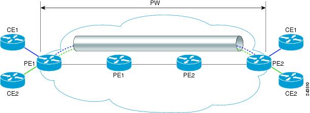
L2VPN Pseudowire Defined
An L2VPN pseudowire (PW) is a tunnel established between two provider edge (PE) routers across the core carrying the Layer 2 payload encapsulated as MPLS data, as shown in Figure 1. This helps carriers migrate from traditional Layer 2 networks such as Frame Relay and ATM to an MPLS core. The PWs between two PE routers are located within the same autonomous system (AS). Routers PE1 and PE2 are called terminating PE routers (T-PEs). Attachment circuits are bounded to the PW on these PE routers.
Figure 1 An L2VPN Pseudowire
L2VPN Multisegment Pseudowire Defined
An L2VPN multisegment pseudowire (MS-PW) is a set of two or more PW segments that function as a single PW, as shown in Figure 2. It is also known as switched PW. MS-PWs span multiple cores or autonomous systems of the same or different carrier networks. An L2VPN MS-PW can include up to 254 PW segments.
Figure 2 A Multisegment Pseudowire

The end routers are called terminating PE routers (T-PEs), and the switching routers are called S-PE routers. The S-PE router terminates the tunnels of the preceding and succeeding PW segments in an MS-PW. The S-PE router can switch the control and data planes of the preceding and succeeding PW segments of the MS-PW. An MS-PW is declared to be up when all the single-segment PWs are up. For more information, see the L2VPN Pseudowire Switching document.
With the L2VPN Multisegment Pseudowire feature introduced in Cisco IOS Release 12.2(33)SRE, the pseudowires are created statically, and FEC 128 information is used to exchange the information about each AS.
MPLS OAM Support for Multisegment Pseudowires
You can use the ping mpls and trace mpls commands to verify that all the segments of the MPLS multisegment pseudowire are operating.
You can use the ping mpls command to verify connectivity at the following pseudowire points:
•![]() From one end of the pseudowire to the other
From one end of the pseudowire to the other
•![]() From one of the pseudowires to a specific segment
From one of the pseudowires to a specific segment
•![]() The segment between two adjacent S-PE routers
The segment between two adjacent S-PE routers
You can use the trace mpls command to verify connectivity at the following pseudowire points:
•![]() From one end of the pseudowire to the other
From one end of the pseudowire to the other
•![]() From one of the pseudowires to a specific segment
From one of the pseudowires to a specific segment
•![]() The segment between two adjacent S-PE routers
The segment between two adjacent S-PE routers
•![]() A range of segments
A range of segments
MPLS OAM Support for L2VPN VPLS Inter-AS Option B
The L2VPN VPLS Inter-AS Option B feature introduced in Cisco IOS Release 15.1(1)S uses multisegment pseudowires to connect Autonomous System Border Routers (ASBRs) in different autonomous systems. With this feature, the pseudowires are created dynamically, and FEC 129 information is used to exchange the information about each ASBR.
The differences between static multisegment pseudowires and dynamic multisegment pseudowires are listed in Table 1.
For more information about the L2VPN VPLS Inter-AS Option B feature, see L2VPN VPLS Inter-AS Option B.
How to Configure L2VPN Multisegment Pseudowires
The following sections outline the tasks for configuring and verifying L2VPN multisegment pseudowires:
•![]() Configuring L2VPN Multisegment Pseudowires (required)
Configuring L2VPN Multisegment Pseudowires (required)
•![]() Displaying Information About the L2VPN Multisegment Pseudowires (optional)
Displaying Information About the L2VPN Multisegment Pseudowires (optional)
•![]() Verifying Multisegment Pseudowires with ping mpls and trace mpls Commands (optional)
Verifying Multisegment Pseudowires with ping mpls and trace mpls Commands (optional)
Configuring L2VPN Multisegment Pseudowires
Perform the following steps on the S-PE routers to create L2VPN multisegment pseudowires.
Cisco 7600 Router-Specific Instructions
If the Cisco 7600 router is the penultimate hop router connected to the S-PE or T-PE router, issue the following commands on the S-PE or T-PE routers:
•![]() mpls ldp explicit-null
mpls ldp explicit-null
•![]() no mls mpls explicit-null propagate-ttl
no mls mpls explicit-null propagate-ttl
SUMMARY STEPS
1. ![]() enable
enable
2. ![]() configure terminal
configure terminal
3. ![]() mpls label protocol ldp
mpls label protocol ldp
4. ![]() mpls ldp router-id interface force
mpls ldp router-id interface force
5. ![]() pseudowire-class name
pseudowire-class name
6. ![]() encapsulation mpls
encapsulation mpls
7. ![]() switching tlv
switching tlv
8. ![]() exit
exit
9. ![]() l2 vfi name point-to-point
l2 vfi name point-to-point
10. ![]() description string
description string
11. ![]() neighbor ip-address vcid {encapsulation mpls | pw-class pw-class-name}
neighbor ip-address vcid {encapsulation mpls | pw-class pw-class-name}
DETAILED STEPS
Displaying Information About the L2VPN Multisegment Pseudowires
Perform the following task to display the status of L2VPN multisegment pseudowires.
SUMMARY STEPS
1. ![]() show mpls l2transport binding
show mpls l2transport binding
2. ![]() show mpls l2transport vc detail
show mpls l2transport vc detail
DETAILED STEPS
Step 1 ![]() show mpls l2transport binding
show mpls l2transport binding
Use the show mpls l2transport binding command to display information about the pseudowire switching point, as shown in bold in the output. (In the following examples PE1 and PE4 are the T-PE routers.)
Router# show mpls l2transport binding
Destination Address: 10.1.1.1, VC ID: 102
Local Label: 17
Cbit: 1, VC Type: Ethernet, GroupID: 0
MTU: 1500, Interface Desc: n/a
VCCV: CC Type: CW [1], RA [2], TTL [3]
CV Type: LSPV [2]
Remote Label: 16
Cbit: 1, VC Type: Ethernet, GroupID: 0
MTU: 1500, Interface Desc: n/a
VCCV: CC Type: CW [1], RA [2], TTL [3]
CV Type: LSPV [2]
PW Switching Point:
Vcid local IP addr remote IP addr Description
101 10.11.11.11 10.20.20.20 PW Switching Point PE3
100 10.20.20.20 10.11.11.11 PW Switching Point PE2
Step 2 ![]() show mpls l2transport vc detail
show mpls l2transport vc detail
Use the show mpls l2transport vc detail command to display status of the pseudowire switching point. In the following example, the output (shown in bold) displays the segment that is the source of the fault of the multisegment pseudowire:
Router# show mpls l2transport vc detail
Local interface: Se3/0 up, line protocol up, HDLC up
Destination address: 12.1.1.1, VC ID: 100, VC status: down
Output interface: Se2/0, imposed label stack {23}
Preferred path: not configured
Default path: active
Next hop: point2point
Create time: 00:03:02, last status change time: 00:01:41
Signaling protocol: LDP, peer 10.1.1.1:0 up
Targeted Hello: 10.1.1.4(LDP Id) -> 10.1.1.1, LDP is UP
Status TLV support (local/remote) : enabled/supported
LDP route watch : enabled
Label/status state machine : established, LruRrd
Last local dataplane status rcvd: No fault
Last local SSS circuit status rcvd: No fault
Last local SSS circuit status sent: DOWN(PW-tx-fault)
Last local LDP TLV status sent: No fault
Last remote LDP TLV status rcvd: DOWN(PW-tx-fault)
PW Switching Point:
Fault type Vcid local IP addr remote IP addr Description
PW-tx-fault 101 10.1.1.1 10.1.1.1 S-PE2
Last remote LDP ADJ status rcvd: No fault
MPLS VC labels: local 19, remote 23
Group ID: local 0, remote 0
MTU: local 1500, remote 1500
Remote interface description:
Sequencing: receive disabled, send disabled
VC statistics:
packet totals: receive 16, send 27
byte totals: receive 2506, send 3098
packet drops: receive 0, seq error 0, send 0
Verifying Multisegment Pseudowires with ping mpls and trace mpls Commands
You can use ping mpls and trace mpls commands to verify connectivity in multisegment pseudowires.
Restrictions
Some ping mpls and trace mpls keywords that are available with IPv4 LDP or traffic engineering (TE) are not available with pseudowire.
The following keywords are not available with the ping mpls pseudowire command:
•![]() dsmap
dsmap
•![]() flags
flags
•![]() force-explicit-null
force-explicit-null
•![]() output
output
•![]() revision
revision
•![]() ttl
ttl
The following keywords are not available with the trace mpls pseudowire command:
•![]() flags
flags
•![]() force-explicit-null
force-explicit-null
•![]() output
output
•![]() revision
revision
•![]() ttl
ttl
SUMMARY STEPS
1. ![]() ping mpls pseudowire destination-address vc-id [segment segment-number]
ping mpls pseudowire destination-address vc-id [segment segment-number]
2. ![]() trace mpls pseudowire destination-address vc-id segment segment-number [segment-number]
trace mpls pseudowire destination-address vc-id segment segment-number [segment-number]
DETAILED STEPS
Step 1 ![]() ping mpls pseudowire destination-address vc-id [segment segment-number]
ping mpls pseudowire destination-address vc-id [segment segment-number]
Where:
•![]() destination-address is the address of the S-PE router, which is the end of the segment from the direction of the source.
destination-address is the address of the S-PE router, which is the end of the segment from the direction of the source.
•![]() vc-id is the VC ID of the segment from the source to the next PE router.
vc-id is the VC ID of the segment from the source to the next PE router.
•![]() segment segment-number is optional and specifies the segment you want to ping.
segment segment-number is optional and specifies the segment you want to ping.
The following examples use the topology shown in Figure 2:
•![]() To perform an end-to-end ping operation from T-PE1 to T-PE2, enter the following command. destination-address is S-PE1 and vc-id is the VC between T-PE1 and S-PE1.
To perform an end-to-end ping operation from T-PE1 to T-PE2, enter the following command. destination-address is S-PE1 and vc-id is the VC between T-PE1 and S-PE1.
ping mpls pseudowire destination-address vc-id
•![]() To perform a ping operation from T-PE1 to segment 2, enter the following command. destination-address is S-PE1 and vc-id is the VC between T-PE1 and S-PE1.
To perform a ping operation from T-PE1 to segment 2, enter the following command. destination-address is S-PE1 and vc-id is the VC between T-PE1 and S-PE1.
ping mpls pseudowire destination-address vc-id segment 2
Step 2 ![]() trace mpls pseudowire destination-address vc-id segment segment-number [segment-number]
trace mpls pseudowire destination-address vc-id segment segment-number [segment-number]
Where:
•![]() destination-address is the address of the next S-PE router from the origin of the trace.
destination-address is the address of the next S-PE router from the origin of the trace.
•![]() vc-id is the VC ID of the segment from which the trace command is issued.
vc-id is the VC ID of the segment from which the trace command is issued.
•![]() segment-number indicates the segment upon which the trace operation will act. If you enter two segment numbers, the traceroute operation will perform a trace on that range of routers.
segment-number indicates the segment upon which the trace operation will act. If you enter two segment numbers, the traceroute operation will perform a trace on that range of routers.
The following examples use the topology shown in Figure 2:
•![]() To perform a trace operation from T-PE1 to segment 2 of the multisegment pseudowire, enter the following command. destination-address is S-PE1 and vc-id is the VC between T-PE1 and S-PE1.
To perform a trace operation from T-PE1 to segment 2 of the multisegment pseudowire, enter the following command. destination-address is S-PE1 and vc-id is the VC between T-PE1 and S-PE1.
trace mpls pseudowire destination-address vc-id segment 2
This example performs a trace from T-PE1 to S-PE2.
•![]() To perform a trace operation on a range of segments, enter the following command. This example performs a trace from S-PE2 to T-PE2. destination-address is S-PE1 and vc-id is the VC between T-PE1 and S-PE1.
To perform a trace operation on a range of segments, enter the following command. This example performs a trace from S-PE2 to T-PE2. destination-address is S-PE1 and vc-id is the VC between T-PE1 and S-PE1.
trace mpls pseudowire destination-address vc-id segment 2 4
The following commands perform trace operations on S-PE router 10.10.10.9, first on segment 1, then on segment 2.
Segment 1 trace:
Router# trace mpls pseudowire 10.10.10.9 220 segment 1
Tracing MS-PW segments within range [1-1] peer address 10.10.10.9 and timeout 2 seconds
Codes: '!' - success, 'Q' - request not sent, '.' - timeout,
'L' - labeled output interface, 'B' - unlabeled output interface,
'D' - DS Map mismatch, 'F' - no FEC mapping, 'f' - FEC mismatch,
'M' - malformed request, 'm' - unsupported tlvs, 'N' - no label entry,
'P' - no rx intf label prot, 'p' - premature termination of LSP,
'R' - transit router, 'I' - unknown upstream index,
'X' - unknown return code, 'x' - return code 0
Type escape sequence to abort.
L 1 10.10.9.9 0 ms [Labels: 18 Exp: 0]
local 10.10.10.22 remote 10.10.10.9 vc id 220
Segment 2 trace:
Router# trace mpls pseudowire 10.10.10.9 220 segment 2
Tracing MS-PW segments within range [1-2] peer address 10.10.10.9 and timeout 2 seconds
Codes: '!' - success, 'Q' - request not sent, '.' - timeout,
'L' - labeled output interface, 'B' - unlabeled output interface,
'D' - DS Map mismatch, 'F' - no FEC mapping, 'f' - FEC mismatch,
'M' - malformed request, 'm' - unsupported tlvs, 'N' - no label entry,
'P' - no rx intf label prot, 'p' - premature termination of LSP,
'R' - transit router, 'I' - unknown upstream index,
'X' - unknown return code, 'x' - return code 0
Type escape sequence to abort.
L 1 10.10.9.9 4 ms [Labels: 18 Exp: 0]
local 10.10.10.22 remote 10.10.10.9 vc id 220
! 2 10.10.3.3 4 ms [Labels: 16 Exp: 0]
local 10.10.10.9 remote 10.10.10.3 vc id 220
Verifying L2VPN VPLS Inter-AS Option B with ping mpls and trace mpls Commands
You can use ping mpls and trace mpls commands to verify connectivity in configurations using the L2VPN VPLS Inter-AS Option B feature. For end-to-end ping and trace operations, you enter the destination address of the T-PE router at the other end of the pseudowire.
Restrictions
Some ping mpls and trace mpls keywords that are available with IPv4 LDP or traffic engineering (TE) are not available with pseudowire.
The following keywords are not available with the ping mpls pseudowire command:
•![]() dsmap
dsmap
•![]() flags
flags
•![]() force-explicit-null
force-explicit-null
•![]() output
output
•![]() revision
revision
•![]() ttl
ttl
The following keywords are not available with the trace mpls pseudowire command:
•![]() flags
flags
•![]() force-explicit-null
force-explicit-null
•![]() output
output
•![]() revision
revision
•![]() ttl
ttl
SUMMARY STEPS
1. ![]() ping mpls pseudowire destination-address vc-id [segment segment-number]
ping mpls pseudowire destination-address vc-id [segment segment-number]
2. ![]() trace mpls pseudowire destination-address vc-id segment segment-number [segment-number]
trace mpls pseudowire destination-address vc-id segment segment-number [segment-number]
DETAILED STEPS
Step 1 ![]() ping mpls pseudowire destination-address vc-id [segment segment-number]
ping mpls pseudowire destination-address vc-id [segment segment-number]
Where:
•![]() destination-address is the address of the T-PE2 router at the other end of the pseudowire.
destination-address is the address of the T-PE2 router at the other end of the pseudowire.
•![]() vc-id is the VC ID between T-PE1 and S-PE1.
vc-id is the VC ID between T-PE1 and S-PE1.
•![]() segment segment-number is optional and specifies the segment you want to ping.
segment segment-number is optional and specifies the segment you want to ping.
The following examples use the topology shown in Figure 2:
•![]() To perform an end-to-end ping operation from T-PE1 to T-PE2, enter the following command. destination-address is T-PE2 and vc-id is the VC between T-PE1 and S-PE1.
To perform an end-to-end ping operation from T-PE1 to T-PE2, enter the following command. destination-address is T-PE2 and vc-id is the VC between T-PE1 and S-PE1.
ping mpls pseudowire destination-address vc-id
Step 2 ![]() trace mpls pseudowire destination-address vc-id segment segment-number [segment-number]
trace mpls pseudowire destination-address vc-id segment segment-number [segment-number]
Where:
•![]() destination-address is the address of the T-PE2 router at the other end of the pseudowire.
destination-address is the address of the T-PE2 router at the other end of the pseudowire.
•![]() vc-id is the VC ID between T-PE1 and S-PE1.
vc-id is the VC ID between T-PE1 and S-PE1.
•![]() segment-number indicates the segment upon which the trace operation will act. If you enter two segment numbers, the traceroute operation will perform a trace on that range of routers.
segment-number indicates the segment upon which the trace operation will act. If you enter two segment numbers, the traceroute operation will perform a trace on that range of routers.
The following examples use the topology shown in Figure 2:
•![]() To perform a trace operation from T-PE1 to T-PE2, enter the following command. destination-address is T-PE2 and vc-id is the VC between T-PE1 and S-PE1.
To perform a trace operation from T-PE1 to T-PE2, enter the following command. destination-address is T-PE2 and vc-id is the VC between T-PE1 and S-PE1.
trace mpls pseudowire destination-address vc-id segment 2
This example performs a trace from T-PE1 to T-PE2.
•![]() To perform a trace operation on a range of segments, enter the following command. This example performs a trace from S-PE2 to T-PE2. destination-address is S-PE1 and vc-id is the VC between T-PE1 and S-PE1.
To perform a trace operation on a range of segments, enter the following command. This example performs a trace from S-PE2 to T-PE2. destination-address is S-PE1 and vc-id is the VC between T-PE1 and S-PE1.
trace mpls pseudowire destination-address vc-id segment 2 4
Configuration Examples for L2VPN Multisegment Pseudowires
This section contains a configuration example for a network similar to the one shown in Figure 2.
•![]() Example: Configuring an L2VPN Multisegment Pseudowire
Example: Configuring an L2VPN Multisegment Pseudowire
Example: Configuring an L2VPN Multisegment Pseudowire
The following example does not include all the commands. Unconfigured interfaces are not shown. Portions of the example relevant to L2VPN Multisegment Pseudowires are shown in bold.
T-PE1 Configuration
no ipv6 cef
multilink bundle-name authenticated
frame-relay switching
mpls traffic-eng tunnels
mpls ldp discovery targeted-hello accept
no mpls ip propagate-ttl forwarded
mpls label protocol ldp
!
policy-map exp2
!
interface Loopback0
ip address 10.131.191.252 255.255.255.255
no clns route-cache
!
interface Ethernet0/0
ip address 10.131.191.230 255.255.255.252
mpls label protocol ldp
mpls ip
no clns route-cache
ip rsvp bandwidth 1500 1500
ip rsvp signalling dscp 0
!
interface Ethernet1/0
ip address 10.131.159.246 255.255.255.252
shutdown
no clns route-cache
!
interface Ethernet2/0
no ip address
no cdp enable
!
interface Ethernet2/0.1
encapsulation dot1Q 1000
xconnect 10.131.191.251 333 encapsulation mpls
!
router ospf 1
log-adjacency-changes
passive-interface Loopback0
network 10.131.159.244 0.0.0.3 area 0
network 10.131.191.228 0.0.0.3 area 0
network 10.131.191.232 0.0.0.3 area 0
network 10.131.191.252 0.0.0.0 area 0
network 11.0.0.0 0.0.0.3 area 0
mpls traffic-eng router-id Loopback0
mpls traffic-eng area 0
!
ip classless
!
no ip http server
!
mpls ldp router-id Loopback0 force
end
S-PE1 Configuration
no ipv6 cef
multilink bundle-name authenticated
mpls traffic-eng tunnels
no mpls traffic-eng auto-bw timers
mpls ldp discovery targeted-hello accept
no mpls ip propagate-ttl forwarded
mpls label protocol ldp
!
policy-map exp2
!
l2 vfi sam-sp point-to-point
neighbor 10.131.191.252 333 encapsulation mpls
neighbor 10.131.159.251 222 encapsulation mpls
!
interface Tunnel3
ip unnumbered Loopback0
shutdown
mpls label protocol ldp
mpls accounting experimental input
mpls ip
tunnel mode mpls traffic-eng
tunnel destination 10.131.159.252
tunnel mpls traffic-eng autoroute announce
tunnel mpls traffic-eng priority 2 2
tunnel mpls traffic-eng bandwidth 512
tunnel mpls traffic-eng path-option 1 dynamic
no clns route-cache
service-policy output exp2
!
interface Loopback0
ip address 10.131.191.251 255.255.255.255
no clns route-cache
!
interface Ethernet0/0
ip address 10.131.191.229 255.255.255.252
mpls traffic-eng tunnels
mpls label protocol ldp
mpls ip
no clns route-cache
ip rsvp bandwidth 1500 1500
ip rsvp signalling dscp 0
!
interface Ethernet1/0
ip address 10.131.159.226 255.255.255.252
mpls traffic-eng tunnels
mpls ip
no clns route-cache
service-policy output exp2
ip rsvp bandwidth 1500 1500
ip rsvp signalling dscp 0
!
interface Serial2/0
ip unnumbered Loopback0
mpls ip
no fair-queue
no keepalive
serial restart-delay 0
no clns route-cache
!
router ospf 1
log-adjacency-changes
passive-interface Loopback0
network 10.131.159.224 0.0.0.3 area 0
network 10.131.191.228 0.0.0.3 area 0
network 10.131.191.251 0.0.0.0 area 0
mpls traffic-eng router-id Loopback0
mpls traffic-eng area 0
!
ip classless
!
end
T-PE2 Configuration
no ipv6 cef
no l2tp congestion-control
multilink bundle-name authenticated
frame-relay switching
mpls traffic-eng tunnels
no mpls traffic-eng auto-bw timers frequency 0
mpls ldp discovery targeted-hello accept
no mpls ip propagate-ttl forwarded
mpls label protocol ldp
!
interface Loopback0
ip address 10.131.159.252 255.255.255.255
no clns route-cache
!
interface Ethernet0/0
ip address 10.131.159.230 255.255.255.252
interface Ethernet0/0
ip address 10.131.159.230 255.255.255.252
mpls traffic-eng tunnels
mpls ip
no clns route-cache
ip rsvp bandwidth 1500 1500
ip rsvp signalling dscp 0
!
interface Ethernet1/0
ip address 10.131.159.245 255.255.255.252
shutdown
mpls ip
no clns route-cache
!
interface Ethernet3/0.1
encapsulation dot1Q 1000
xconnect 10.131.159.251 111 encapsulation mpls
!
router ospf 1
log-adjacency-changes
passive-interface Loopback0
network 10.131.122.0 0.0.0.3 area 0
network 10.131.159.228 0.0.0.3 area 0
network 10.131.159.232 0.0.0.3 area 0
network 10.131.159.244 0.0.0.3 area 0
network 10.131.159.252 0.0.0.0 area 0
network 11.0.0.0 0.0.0.3 area 0
network 19.0.0.0 0.0.0.255 area 0
mpls traffic-eng router-id Loopback0
mpls traffic-eng area 0
end
S-PE2 configuration
no ipv6 cef
no l2tp congestion-control
multilink bundle-name authenticated
mpls traffic-eng tunnels
no mpls traffic-eng auto-bw timers frequency 0
mpls ldp discovery targeted-hello accept
no mpls ip propagate-ttl forwarded
mpls label protocol ldp
!
l2 vfi sam-sp point-to-point
neighbor 10.131.159.252 111 encapsulation mpls
neighbor 10.131.191.251 222 encapsulation mpls
!
!
interface Loopback0
ip address 10.131.159.251 255.255.255.255
!
interface Ethernet0/0
interface Ethernet0/0
ip address 10.131.159.229 255.255.255.252
mpls traffic-eng tunnels
mpls accounting experimental input
mpls ip
ip rsvp bandwidth 1500 1500
ip rsvp signalling dscp 0
!
interface Ethernet1/0
ip address 10.131.159.225 255.255.255.252
mpls traffic-eng tunnels
mpls ip
ip rsvp bandwidth 1500 1500
ip rsvp signalling dscp 0
!
router ospf 1
log-adjacency-changes
passive-interface Loopback0
network 10.131.159.224 0.0.0.3 area 0
network 10.131.159.228 0.0.0.3 area 0
network 10.131.159.251 0.0.0.0 area 0
network 19.0.0.0 0.0.0.255 area 0
mpls traffic-eng router-id Loopback0
mpls traffic-eng area 0
!
end
Additional References
Related Documents
|
|
|
|---|---|
Cisco IOS commands |
|
MPLS commands |
|
Layer 2 VPNS |
|
L2VPN VPLS Inter-AS Option B |
Standards
|
|
|
|---|---|
No new or modified standards are supported by this feature, and support for existing standards has not been modified by this feature. |
— |
MIBs
RFCs
|
|
|
|---|---|
RFC 4379 |
Detecting Multi-Protocol Label Switched (MPLS) Data Plane Failures |
RFC 4447 |
Pseudowire Setup and Maintenance Using the Label Distribution Protocol (LDP) |
RFC 5085 |
Technical Assistance
Feature Information for L2VPN Multisegment Pseudowires
Table 2 lists the release history for this feature.
Use Cisco Feature Navigator to find information about platform support and software image support. Cisco Feature Navigator enables you to determine which software images support a specific software release, feature set, or platform. To access Cisco Feature Navigator, go to http://www.cisco.com/go/cfn. An account on Cisco.com is not required.

Note ![]() Table 2 lists only the software release that introduced support for a given feature in a given software release train. Unless noted otherwise, subsequent releases of that software release train also support that feature.
Table 2 lists only the software release that introduced support for a given feature in a given software release train. Unless noted otherwise, subsequent releases of that software release train also support that feature.
 Feedback