-
- MPLS Traffic Engineering - LSP Attributes
- MPLS Traffic Engineering (TE) - Autotunnel Primary and Backup
- MPLS Traffic Engineering - AutoTunnel Mesh Groups
- MPLS Traffic Engineering - Verbatim Path Support
- MPLS Traffic Engineering - RSVP Hello State Timer
- MPLS Traffic Engineering Forwarding Adjacency
- MPLS Traffic Engineering (TE) - Class-based Tunnel Selection
- MPLS Traffic Engineering - Interarea Tunnels
- MPLS TE - Bundled Interface Support
- MPLS Traffic Engineering�Automatic Bandwidth Adjustment for TE Tunnels
- MPLS Point-to-Multipoint Traffic Engineering
- MPLS Traffic Engineering�Tunnel Source
-
- MPLS Traffic Engineering - Inter-AS TE
- MPLS Traffic Engineering - Shared Risk Link Groups
- MPLS Traffic Engineering (TE) - Autotunnel Primary and Backup
- MPLS Traffic Engineering (TE) - Path Protection
- MPLS Traffic Engineering (TE) - Fast Reroute (FRR) Link and Node Protection
- MPLS TE: Link and Node Protection, with RSVP Hellos Support (with Fast Tunnel Interface Down Detection)
- MPLS Traffic Engineering: BFD-triggered Fast Reroute (FRR)
-
- MPLS MTU Command Changes
- AToM Static Pseudowire Provisioning
- MPLS Pseudowire Status Signaling
- L2VPN Interworking
- L2VPN Pseudowire Redundancy
- L2VPN Pseudowire Switching
- VPLS Autodiscovery: BGP Based
- H-VPLS N-PE Redundancy for QinQ and MPLS Access
- L2VPN Multisegment Pseudowires
- QOS Policy Support on L2VPN ATM PVPs
- L2VPN: Pseudowire Preferential Forwarding
-
- Configuring MPLS Layer 3 VPNs
- MPLS VPN Half-Duplex VRF
- MPLS VPN�Show Running VRF
- MPLS VPN�VRF CLI for IPv4 and IPv6 VPNs
- MPLS VPN--BGP Local Convergence
- MPLS VPN�Route Target Rewrite
- MPLS VPN�Per VRF Label
- MPLS VPN 6VPE per VRF Label
- MPLS Multi-VRF (VRF Lite) Support
- BGP Best External
- BGP PIC Edge for IP and MPLS-VPN
- MPLS VPN - L3VPN over GRE
- Dynamic Layer-3 VPNs with Multipoint GRE Tunnels
- MPLS VPN over mGRE
-
- MPLS LSP Ping/Traceroute for LDP/TE, and LSP Ping for VCCV
- MPLS EM�MPLS LSP Multipath Tree Trace
- Pseudowire Emulation Edge-to-Edge MIBs for Ethernet, Frame Relay, and ATM Services
- MPLS Enhancements to Interfaces MIB
- MPLS Label Distribution Protocol MIB Version 8 Upgrade
- MPLS EM�MPLS LDP MIB - RFC 3815
- MPLS Label Switching Router MIB
- MPLS EM�MPLS LSR MIB - RFC 3813
- MPLS Traffic Engineering MIB
- MPLS Traffic Engineering - Fast Reroute MIB
- MPLS EM - TE MIB RFC 3812
- MPLS VPN�MIB Support
- MPLS EM - MPLS VPN MIB RFC4382 Upgrade
-
- MPLS High Availability: Overview
- MPLS High Availability: Command Changes
- MPLS LDP Graceful Restart
- NSF/SSO - MPLS LDP and LDP Graceful Restart
- NSF/SSO: MPLS VPN
- AToM Graceful Restart
- NSF/SSO�Any Transport over MPLS and AToM Graceful Restart
- NSF/SSO - MPLS TE and RSVP Graceful Restart
- ISSU MPLS Clients
- NSF/SSO/ISSU Support for VPLS
- NSF/SSO and ISSU - MPLS VPN 6VPE and 6PE
Cisco IOS Multiprotocol Label Switching Configuration Guide, Release 12.2SR
Bias-Free Language
The documentation set for this product strives to use bias-free language. For the purposes of this documentation set, bias-free is defined as language that does not imply discrimination based on age, disability, gender, racial identity, ethnic identity, sexual orientation, socioeconomic status, and intersectionality. Exceptions may be present in the documentation due to language that is hardcoded in the user interfaces of the product software, language used based on RFP documentation, or language that is used by a referenced third-party product. Learn more about how Cisco is using Inclusive Language.
- Updated:
- February 12, 2008
Chapter: NSF/SSO: MPLS VPN
- Contents
- Prerequisites for NSF/SSO—MPLS VPN
- Restrictions for NSF/SSO—MPLS VPN
- Information About NSF/SSO—MPLS VPN
- How to Configure NSF/SSO—MPLS VPN
- Configuration Examples for NSF/SSO—MPLS VPN
- NSF/SSO—MPLS VPN for a Basic MPLS VPN: Example
- NSF/SSO—MPLS VPN for a CSC Network with a Customer Carrier Who Is an ISP: Example
- NSF/SSO—MPLS VPN for a CSC Network with a Customer Who Is an MPLS VPN Provider: Example
- NSF/SSO—MPLS VPN for a CSC Network That Uses BGP to Distribute MPLS Labels: Example
- NSF/SSO—MPLS VPN for an Inter-AS Network Using BGP to Distribute Routes and MPLS Labels: Example
- NSF/SSO—MPLS VPN for an Inter-AS Network That Uses BGP to Distribute Routes and MPLS Labels over a Non-MPLS VPN Service Provider: Example
NSF/SSO—MPLS VPN
The NSF/SSO—MPLS VPN feature allows a provider edge (PE) router or Autonomous System Border Router (ASBR) (with redundant Route Processors) to preserve data forwarding information in a Multiprotocol Label Switching (MPLS) Virtual Private Network (VPN) when the primary Route Processor (RP) restarts. This feature module describes how to enable Nonstop Forwarding in MPLS VPN networks, including the following types of VPNs:
•![]() Basic MPLS VPNs
Basic MPLS VPNs
•![]() MPLS VPN—Carrier Supporting Carrier
MPLS VPN—Carrier Supporting Carrier
•![]() MPLS VPN—Carrier Supporting Carrier—IPv4 BGP Label Distribution
MPLS VPN—Carrier Supporting Carrier—IPv4 BGP Label Distribution
•![]() MPLS VPN—Interautonomous Systems
MPLS VPN—Interautonomous Systems
•![]() MPLS VPN—Inter-AS—IPv4 BGP Label Distribution
MPLS VPN—Inter-AS—IPv4 BGP Label Distribution
Finding Feature Information in This Module
Your Cisco IOS software release may not support all of the features documented in this module. To reach links to specific feature documentation in this module and to see a list of the releases in which each feature is supported, use the "Feature Information for NSF/SSO—MPLS VPN" section.
Finding Support Information for Platforms and Cisco IOS and Catalyst OS Software Images
Use Cisco Feature Navigator to find information about platform support and Cisco IOS and Catalyst OS software image support. To access Cisco Feature Navigator, go to http://www.cisco.com/go/cfn. An account on Cisco.com is not required.
Contents
•![]() Prerequisites for NSF/SSO—MPLS VPN
Prerequisites for NSF/SSO—MPLS VPN
•![]() Restrictions for NSF/SSO—MPLS VPN
Restrictions for NSF/SSO—MPLS VPN
•![]() Information About NSF/SSO—MPLS VPN
Information About NSF/SSO—MPLS VPN
•![]() How to Configure NSF/SSO—MPLS VPN
How to Configure NSF/SSO—MPLS VPN
•![]() Configuration Examples for NSF/SSO—MPLS VPN
Configuration Examples for NSF/SSO—MPLS VPN
•![]() Feature Information for NSF/SSO—MPLS VPN
Feature Information for NSF/SSO—MPLS VPN
Prerequisites for NSF/SSO—MPLS VPN
The NSF/SSO—MPLS VPN feature has the following prerequisites:
For information about supported hardware, see the release notes for your platform.
Before enabling Stateful Switchover (SSO), you must enable MPLS Label Distrbution Protocol (LDP) Graceful Restart if you use LDP in the core or in the MPLS VPN routing and forwarding instance in an MPLS VPN Carrier Supporting Carrier configuration. See the NSF/SSO-MPLS LDP and MPLS LDP Graceful Restart feature module for more information.
You must enable NSF on the routing protocols running between the provider (P) routers , PE routers, and customer edge (CE) routers. The routing protocols are:
•![]() Border Gateway Protocol (BGP)
Border Gateway Protocol (BGP)
•![]() Open Shortest Path First (OSPF)
Open Shortest Path First (OSPF)
•![]() Intermediate System-to-Intermediate System (IS-IS)
Intermediate System-to-Intermediate System (IS-IS)
Cisco nonstop forwarding support must be configured on the routers for Cisco Express Forwarding. See the Cisco Nonstop Forwarding feature module for more information.
Before enabling the NSF/SSO—MPLS VPN feature, you must have a supported MPLS VPN network configuration. Configuration information is included in the Configuring MPLS VPNs feature module.
Restrictions for NSF/SSO—MPLS VPN
The NSF/SSO—MPLS VPN feature has the following restrictions:
•![]() Tag Distribution Protocol (TDP) sessions are not supported. Only LDP sessions are supported.
Tag Distribution Protocol (TDP) sessions are not supported. Only LDP sessions are supported.
•![]() The NSF/SSO—MPLS VPN feature requires that neighbor networking devices be NSF-aware. Peer routers must support the graceful restart of the protocol used to communicate with the NSF/SSO—MPLS VPN-capable router.
The NSF/SSO—MPLS VPN feature requires that neighbor networking devices be NSF-aware. Peer routers must support the graceful restart of the protocol used to communicate with the NSF/SSO—MPLS VPN-capable router.
•![]() The NSF/SSO—MPLS VPN feature cannot be configured on label-controlled ATM (LC-ATM) interfaces.
The NSF/SSO—MPLS VPN feature cannot be configured on label-controlled ATM (LC-ATM) interfaces.
Information About NSF/SSO—MPLS VPN
To configure NSF/SSO—MPLS VPN, you need to understand the following concepts:
•![]() Elements That Enable NSF/SSO—MPLS VPN to Work
Elements That Enable NSF/SSO—MPLS VPN to Work
•![]() How VPN Prefix Information Is Checkpointed to the Backup Route Processor
How VPN Prefix Information Is Checkpointed to the Backup Route Processor
•![]() How BGP Graceful Restart Preserves Prefix Information During a Restart
How BGP Graceful Restart Preserves Prefix Information During a Restart
•![]() What Happens If a Router Does Not Have NSF/SSO—MPLS VPN Enabled
What Happens If a Router Does Not Have NSF/SSO—MPLS VPN Enabled
Elements That Enable NSF/SSO—MPLS VPN to Work
VPN NSF requires several elements to work:
•![]() VPN NSF uses the BGP Graceful Restart mechanisms defined in the Graceful Restart Internet Engineering Task Force (IETF) specifications and in the Cisco Nonstop Forwarding feature module. BGP Graceful Restart allows a router to create MPLS forwarding entries for VPNv4 prefixes in NSF mode. The forwarding entries are preserved during a restart. BGP also saves prefix and corresponding label information and recovers the information after a restart.
VPN NSF uses the BGP Graceful Restart mechanisms defined in the Graceful Restart Internet Engineering Task Force (IETF) specifications and in the Cisco Nonstop Forwarding feature module. BGP Graceful Restart allows a router to create MPLS forwarding entries for VPNv4 prefixes in NSF mode. The forwarding entries are preserved during a restart. BGP also saves prefix and corresponding label information and recovers the information after a restart.
•![]() The NSF/SSO—MPLS VPN feature also uses NSF for the label distribution protocol in the core network (either MPLS Label Distribution Protocol, traffic engineering, or static labeling).
The NSF/SSO—MPLS VPN feature also uses NSF for the label distribution protocol in the core network (either MPLS Label Distribution Protocol, traffic engineering, or static labeling).
•![]() The NSF/SSO—MPLS VPN feature uses NSF for the Interior Gateway Protocol (IGP) used in the core (OSPF or IS-IS).
The NSF/SSO—MPLS VPN feature uses NSF for the Interior Gateway Protocol (IGP) used in the core (OSPF or IS-IS).
•![]() The NSF/SSO—MPLS VPN feature uses NSF for the routing protocols between the PE and customer CE routers.
The NSF/SSO—MPLS VPN feature uses NSF for the routing protocols between the PE and customer CE routers.
How VPN Prefix Information Is Checkpointed to the Backup Route Processor
When BGP allocates local labels for prefixes, it checkpoints the local label binding in the backup Route Processor. The checkpointing function copies state information from the active Route Processor to the backup Route Processor, thereby ensuring that the backup Route Processor has an identical copy of the latest information. If the active Route Processor fails, the backup Route Processor can take over with no interruption in service. Checkpointing begins when the active Route Processor does a bulk synchronization, which copies all of the local label bindings to the backup Route Processor. After that, the active Route Processor dynamically checkpoints individual prefix label bindings when a label is allocated or freed. This allows forwarding of labeled packets to continue before BGP reconverges.
How BGP Graceful Restart Preserves Prefix Information During a Restart
When a router that is capable of BGP Graceful Restart loses connectivity, the following happens to the restarting router:
1. ![]() The router establishes BGP sessions with other routers and relearns the BGP routes from other routers that are also capable of Graceful Restart. The restarting router waits to receive updates from the neighboring routers. When the neighboring routers send end-of-Routing Information Base (RIB) markers to indicate that they are done sending updates, the restarting router starts sending its own updates.
The router establishes BGP sessions with other routers and relearns the BGP routes from other routers that are also capable of Graceful Restart. The restarting router waits to receive updates from the neighboring routers. When the neighboring routers send end-of-Routing Information Base (RIB) markers to indicate that they are done sending updates, the restarting router starts sending its own updates.
2. ![]() The restarting router accesses the checkpoint database to find the label that was assigned for each prefix. If it finds the label, it advertises it to the neighboring router. If it does not find the label, it allocates a new label and advertises it.
The restarting router accesses the checkpoint database to find the label that was assigned for each prefix. If it finds the label, it advertises it to the neighboring router. If it does not find the label, it allocates a new label and advertises it.
3. ![]() The restarting router removes any stale prefixes after a timer for stale entries expires.
The restarting router removes any stale prefixes after a timer for stale entries expires.
When a peer router that is capable of BGP Graceful Restart encounters a restarting router, it does the following:
1. ![]() The peer router sends all of the routing updates to the restarting router. When it has finished sending updates, the peer router sends an end-of RIB marker to the restarting router.
The peer router sends all of the routing updates to the restarting router. When it has finished sending updates, the peer router sends an end-of RIB marker to the restarting router.
2. ![]() The peer router does not immediately remove the BGP routes learned from the restarting router from its BGP routing table. As it learns the prefixes from the restarting router, the peer refreshes the stale routes if the new prefix and label information matches the old information.
The peer router does not immediately remove the BGP routes learned from the restarting router from its BGP routing table. As it learns the prefixes from the restarting router, the peer refreshes the stale routes if the new prefix and label information matches the old information.
What Happens If a Router Does Not Have NSF/SSO—MPLS VPN Enabled
If a router is not configured for the NSF/SSO—MPLS VPN feature and it attempts to establish a BGP session with a router that is configured with the NSF/SSO—MPLS VPN feature, the two routers create a normal BGP session but do not have the ability to perform the NSF/SSO—MPLS VPN feature.
How to Configure NSF/SSO—MPLS VPN
This section contains the following procedures:
•![]() Configuring NSF Support for Basic VPNs (required)
Configuring NSF Support for Basic VPNs (required)
•![]() Configuring NSF Support for MPLS VPN Interfaces That Use BGP as the Label Distribution Protocol (required)
Configuring NSF Support for MPLS VPN Interfaces That Use BGP as the Label Distribution Protocol (required)
•![]() Verifying the NSF/SSO—MPLS VPN Configuration (optional)
Verifying the NSF/SSO—MPLS VPN Configuration (optional)
Configuring NSF Support for Basic VPNs
Perform this task to configure NSF support for basic VPNs.
Prerequisites
Route Processors must be configured for SSO. See the Stateful Switchover feature module for more information.
If you use LDP in the core or in the virtual routing and forwarding (VRF) instances for MPLS VPN Carrier Supporting Carrier configurations, you must enable the MPLS LDP: NSF/SSO Support and Graceful Restart feature. See the NSF/SSO-MPLS LDP and MPLS LDP Graceful Restart feature module for more information.
You must enable Nonstop Forwarding on the routing protocols running between the P, PE, and CE routers. The routing protocols are OSPF, IS-IS, and BGP. See the Cisco Nonstop Forwarding feature module for more information.
Before enabling the NSF/SSO—MPLS VPN feature, you must have a supported MPLS VPN network configuration. Configuration information is included in the Configuring MPLS VPNs feature module.
SUMMARY STEPS
1. ![]() enable
enable
2. ![]() configure terminal
configure terminal
3. ![]() ip cef [distributed]
ip cef [distributed]
4. ![]() router bgp as-number
router bgp as-number
5. ![]() bgp graceful-restart restart-time secs
bgp graceful-restart restart-time secs
6. ![]() bgp graceful-restart stalepath-time secs
bgp graceful-restart stalepath-time secs
7. ![]() bgp graceful-restart
bgp graceful-restart
8. ![]() end
end
DETAILED STEPS
|
|
|
|
|---|---|---|
Step 1 |
enable Router> enable |
Enables privileged EXEC mode. • |
Step 2 |
configure terminal Router# configure terminal |
Enters global configuration mode. |
Step 3 |
ip cef [distributed] Router(config)# ip cef distributed |
Enables Cisco Express Forwarding • |
Step 4 |
router bgp as-number Router(config)# router bgp 1 |
Configures a BGP routing process and enters router configuration mode. • Valid numbers are from 0 to 65535. Private autonomous system numbers that can be used in internal networks range from 64512 to 65535. |
Step 5 |
bgp graceful-restart restart-time secs
Router(config-router)# bgp graceful-restart restart-time 200 |
(Optional) Specifies the maximum time to wait for a graceful-restart-capable neighbor to come back up after a restart. The default is 120 seconds. The valid range is from 1 to 3600 seconds. |
Step 6 |
bgp graceful-restart stalepath-time secs
Router(config-router)# bgp graceful-restart stalepath-time 400 |
(Optional) Specifies the maximum time to hold on to the stale paths of a gracefully restarted peer. All stale paths are deleted after the expiration of this timer. The default is 360 seconds. The valid range is from 1 to 3600 seconds. |
Step 7 |
bgp graceful-restart Router(config-router)# bgp graceful-restart |
Enables BGP Graceful Restart on the router. See Cisco Nonstop Forwarding for more information about the bgp graceful-restart command. |
Step 8 |
end Router(config-router)# end |
(Optional) Exits to privileged EXEC mode. |
Configuring NSF Support for MPLS VPN Interfaces That Use BGP as the Label Distribution Protocol
The following VPN features require special configuration for the NSF/SSO—MPLS VPN feature:
•![]() MPLS VPN—Carrier Supporting Carrier—IPv4 BGP Label Distribution
MPLS VPN—Carrier Supporting Carrier—IPv4 BGP Label Distribution
•![]() MPLS VPN—Inter-AS—IPv4 BGP Label Distribution
MPLS VPN—Inter-AS—IPv4 BGP Label Distribution
You must issue an extra command, mpls forwarding bgp, on the interfaces that use BGP to distribute MPLS labels and routes. Use the following procedure to configure the NSF/SSO—MPLS VPN feature in these MPLS VPNs.
Prerequisites
•![]() Make sure your MPLS VPN is configured for Carrier Supporting Carrier (CSC) or Inter-AS with BGP as the label distribution protocol.
Make sure your MPLS VPN is configured for Carrier Supporting Carrier (CSC) or Inter-AS with BGP as the label distribution protocol.
•![]() Configure NSF/SSO—MPLS VPN first, as described in "Configuring NSF Support for Basic VPNs" section.
Configure NSF/SSO—MPLS VPN first, as described in "Configuring NSF Support for Basic VPNs" section.
SUMMARY STEPS
1. ![]() enable
enable
2. ![]() configure terminal
configure terminal
3. ![]() ip cef [distributed]
ip cef [distributed]
4. ![]() interface slot/port
interface slot/port
5. ![]() mpls forwarding bgp
mpls forwarding bgp
DETAILED STEPS
Verifying the NSF/SSO—MPLS VPN Configuration
This section explains how to verify a configuratin that has the the NSF/SSO—MPLS VPN feature.
•![]() See the Cisco Nonstop Forwarding feature module for verification procedures for BGP, OSPF, and IS-IS.
See the Cisco Nonstop Forwarding feature module for verification procedures for BGP, OSPF, and IS-IS.
•![]() See the NSF/SSO-MPLS LDP and MPLS LDP Graceful Restart feature module for verification procedures for the MPLS LDP: NSF/SSO feature
See the NSF/SSO-MPLS LDP and MPLS LDP Graceful Restart feature module for verification procedures for the MPLS LDP: NSF/SSO feature
•![]() See the verification information included in the Configuring MPLS VPNs feature module.
See the verification information included in the Configuring MPLS VPNs feature module.
SUMMARY STEPS
1. ![]() show ip bgp vpnv4 all labels
show ip bgp vpnv4 all labels
2. ![]() show ip bgp vpnv4 all neighbors
show ip bgp vpnv4 all neighbors
3. ![]() show ip bgp labels
show ip bgp labels
4. ![]() show ip bgp neighbors
show ip bgp neighbors
DETAILED STEPS
Step 1 ![]() show ip bgp vpnv4 all labels
show ip bgp vpnv4 all labels
This command displays incoming and outgoing BGP labels for each route distinguisher. The following is sample output from the command:
Router# show ip bgp vpnv4 all labels
Network Next Hop In label/Out label
Route Distinguisher: 100:1 (vpn1)
10.3.0.0/16 10.0.0.5 25/20
10.0.0.1 25/23
10.0.0.2 25/imp-null
10.0.0.9/32 10.0.0.1 24/22
10.0.0.2 24/imp-null
Step 2 ![]() show ip bgp vpnv4 all neighbors
show ip bgp vpnv4 all neighbors
This command displays whether the BGP peers are capable of Graceful Restart. The following is sample output from the command:
Router# show ip bgp vpnv4 all neighbors
BGP neighbor is 10.0.0.1, remote AS 100, internal link
BGP version 4, remote router ID 10.0.0.1
BGP state = Established, up for 02:49:47
Last read 00:00:47, hold time is 180, keepalive interval is 60 seconds
Neighbor capabilities:
Route refresh: advertised and received(new)
Address family VPNv4 Unicast: advertised and received
Graceful Restart Capabilty: advertised and received
Remote Restart timer is 120 seconds
Address families preserved by peer:
VPNv4 Unicast
.
.
.
Step 3 ![]() show ip bgp labels
show ip bgp labels
This command displays information about MPLS labels in the Exterior Border Gateway Protocol (EBGP) route table. The following is sample output from the command:
Router# show ip bgp labels
Network Next Hop In label/Out label
10.3.0.0/16 10.0.0.1 imp-null/imp-null
0.0.0.0 imp-null/nolabel
10.0.0.9/32 10.0.0.1 21/29
10.0.0.11/32 10.0.0.1 24/38
10.0.0.13/32 0.0.0.0 imp-null/nolabel
10.0.0.15/32 10.0.0.1 29/nolabel
10.0.0.1 29/21
Step 4 ![]() show ip bgp neighbors
show ip bgp neighbors
This command displays whether the BGP peers are capable of Graceful Restart. The following is sample output from the command:
Router# show ip bgp neighbors
BGP neighbor is 10.0.0.1, remote AS 100, external link
BGP version 4, remote router ID 10.0.0.5
BGP state = Established, up for 02:54:19
Last read 00:00:18, hold time is 180, keepalive interval is 60 seconds
Neighbor capabilities:
Route refresh: advertised and received(new)
Address family IPv4 Unicast: advertised and received
ipv4 MPLS Label capability: advertised and received
Graceful Restart Capabilty: advertised and received
Remote Restart timer is 120 seconds
Address families preserved by peer:
IPv4 Unicast
.
.
.
Configuration Examples for NSF/SSO—MPLS VPN
This section includes six configuration examples. The first configuration example shows the most simple configuration, a basic VPN configuration. The second, third, and fourth examples show different CSC VPN configurations. The fourth example hows a CSC VPN configuration that uses BGP as the MPLS label distribution method and therefore requires the mpls forwarding bgp command. The last two examples show Inter-AS configurations.
•![]() NSF/SSO—MPLS VPN for a Basic MPLS VPN: Example
NSF/SSO—MPLS VPN for a Basic MPLS VPN: Example
•![]() NSF/SSO—MPLS VPN for a CSC Network with a Customer Carrier Who Is an ISP: Example
NSF/SSO—MPLS VPN for a CSC Network with a Customer Carrier Who Is an ISP: Example
•![]() NSF/SSO—MPLS VPN for a CSC Network with a Customer Who Is an MPLS VPN Provider: Example
NSF/SSO—MPLS VPN for a CSC Network with a Customer Who Is an MPLS VPN Provider: Example
•![]() NSF/SSO—MPLS VPN for a CSC Network That Uses BGP to Distribute MPLS Labels: Example
NSF/SSO—MPLS VPN for a CSC Network That Uses BGP to Distribute MPLS Labels: Example
•![]() NSF/SSO—MPLS VPN for an Inter-AS Network Using BGP to Distribute Routes and MPLS Labels: Example
NSF/SSO—MPLS VPN for an Inter-AS Network Using BGP to Distribute Routes and MPLS Labels: Example
NSF/SSO—MPLS VPN for a Basic MPLS VPN: Example
In this example, the NSF/SSO—MPLS VPN feature is enabled on the existing MPLS VPN configuration.
Enabling SSO on a Cisco 7500 Series Router
The following commands are used to enable SSO on the Cisco 7500 series routers:
•![]() hw-module slot
hw-module slot
•![]() redundancy
redundancy
•![]() mode sso
mode sso
The configuration examples are the same for both platforms with the exception that the following configuration boot commands are seen in the beginning of a Cisco 7500 series router configuration (and not in a Cisco 10000 series router configuration):
boot system slot0:rsp-pv-mz
hw-module slot 2 image slot0:rsp-pv-mz
hw-module slot 3 image slot0:rsp-pv-mz
Enabling SSO on a Cisco 10000 Series Router
The SSO mode is enabled by default.
Enabling NSF on Both the Cisco 7500 Series and Cisco 10000 Series Routers
The following commands are used to enable NSF for the routing protocols, such as BGP and OSPF, and for the label distribution protocols, such as BGP and LDP:
•![]() bgp graceful-restart restart-time
bgp graceful-restart restart-time
•![]() bgp graceful-restart stalepath-time
bgp graceful-restart stalepath-time
•![]() bgp graceful-restart
bgp graceful-restart
•![]() nsf enforce global
nsf enforce global

Note ![]() In the configuration example, the NSF/SSO commands are bold-faced and any platform-specific commands are highlighted by arrows.
In the configuration example, the NSF/SSO commands are bold-faced and any platform-specific commands are highlighted by arrows.
Figure 1 shows the configuration of the NSF/SSO—MPLS VPN feature on the PE and CE routers.
Figure 1 MPLS VPN Configuration with MPLS VPN: NSF/SSO
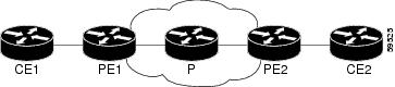
Note ![]() LDP is the default MPLS label protocol.
LDP is the default MPLS label protocol.
The following configuration examples show the configuration of the NSF/SSO—MPLS VPN feature on the CE and PE routers.
CE1 Router
ip cef
no ip domain-lookup
!
interface Loopback0
ip address 10.10.10.10 255.255.255.255
!
interface Ethernet4
ip address 10.0.0.1 255.0.0.0
media-type 10BaseT
!
router ospf 100
redistribute bgp 101
nsf enforce global
passive-interface Ethernet4
network 10.0.0.0 0.255.255.255 area 100
!
router bgp 101
no synchronization
bgp graceful-restart restart-time 120
bgp graceful-restart stalepath-time 360
bgp graceful-restart network 10.0.0.0
network 10.0.0.0
neighbor 10.0.0.2 remote-as 100
PE1 Router
redundancy
mode sso
!
ip cef distributed
mpls ldp graceful-restart
mpls label protocol ldp
ip vrf vpn1
rd 100:1
route-target export 100:1
route-target import 100:1
no mpls aggregate-statistics
!
interface Loopback0
ip address 10.12.12.12 255.255.255.255
!
interface Ethernet1/4 =====> interface FastEthernet1/1/4 on a Cisco 10000 series router
ip vrf forwarding vpn1
ip address 10.0.0.2 255.0.0.0
!
mpls ip
interface ATM3/0 =====> interface ATM3/0/0 on a Cisco 10000 series router
no ip address
!
interface ATM3/0.1 point-to-point ==> interface ATM3/0/0.1 point-to-point on a Cisco 10000
ip unnumbered Loopback0
mpls ip
!
router ospf 100
passive-interface Ethernet1/4 ===> passive-interface FastEthernet1/1/4 on a Cisco 10000
nsf enforce global
network 10.0.0.0 0.255.255.255 area 100
!
router bgp 100
no synchronization
bgp graceful-restart restart-time 120
bgp graceful-restart stalepath-time 360
bgp graceful-restart
no bgp default ipv4-unicast
neighbor 10.14.14.14 remote-as 100
neighbor 10.14.14.14 update-source Loopback0
!
address-family ipv4 vrf vpn1
neighbor 10.0.0.1 remote-as 101
neighbor 10.0.0.1 activate
exit-address-family
!
address-family vpnv4
neighbor 10.14.14.14 activate
neighbor 10.14.14.14 send-community extended
exit-address-family
PE2 Router
redundancy
mode sso
!
ip cef distributed
mpls ldp graceful-restart
mpls label protocol ldp
!
ip vrf vpn1
rd 100:1
route-target export 100:1
route-target import 100:1
no mpls aggregate-statistics
!
!
interface Loopback0
ip address 10.14.14.14 255.255.255.255
!
interface ATM1/0 =====> interface ATM1/0/0 on a Cisco 10000 series router
no ip address
!
interface ATM1/0.1 point-to-point ==> interface ATM1/0/0.1 point-to-point on a Cisco 10000
ip unnumbered Loopback0
mpls ip
!
interface FastEthernet3/0/0
ip vrf forwarding vpn1
ip address 10.0.0.1 255.0.0.0
ip route-cache distributed
mpls ip
!
router ospf 100
nsf enforce global
passive-interface FastEthernet3/0/0
network 10.0.0.0 0.255.255.255 area 100
!
router bgp 100
no synchronization
bgp graceful-restart restart-time 120
bgp graceful-restart stalepath-time 360
bgp graceful-restart
no bgp default ipv4-unicast
neighbor 10.12.12.12 remote-as 100
neighbor 10.12.12.12 update-source Loopback0
!
address-family ipv4 vrf vpn1
neighbor 10.0.0.2 remote-as 102
neighbor 10.0.0.2 activate
exit-address-family
!
address-family vpnv4
neighbor 10.12.12.12 activate
neighbor 10.12.12.12 send-community extended
exit-address-family
CE2 Router
ip cef
!
interface Loopback0
ip address 10.13.13.13 255.255.255.255
!
interface FastEthernet0
ip address 10.0.0.2 255.0.0.0
no ip mroute-cache
!
router ospf 100
redistribute bgp 102
nsf enforce global
passive-interface FastEthernet0
network 10.0.0.0 0.255.255.255 area 100
!
router bgp 102
no synchronization
bgp graceful-restart restart-time 120
bgp graceful-restart stalepath-time 360
bgp graceful-restart
network 10.0.0.0
network 10.0.0.0
neighbor 10.0.0.1 remote-as 100
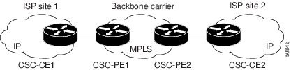
NSF/SSO—MPLS VPN for a CSC Network with a Customer Carrier Who Is an ISP: Example
In this example, MPLS VPN SSO and NSF are configured on the existing MPLS CSC VPN configuration. In the CSC network configuration, the customer carrier is an Internet Service Provider (ISP), as shown in Figure 2.
Enabling SSO on a Cisco 7500 Series Router
The following commands are used to enable SSO on the Cisco 7500 series routers:
•![]() hw-module slot
hw-module slot
•![]() redundancy
redundancy
•![]() mode sso
mode sso
The configuration examples are the same for both platforms with the exception that the following configuration boot commands are seen in the beginning of a Cisco 7500 series router configuration (and not in a Cisco 10000 series router configuration):
boot system slot0:rsp-pv-mz
hw-module slot 2 image slot0:rsp-pv-mz
hw-module slot 3 image slot0:rsp-pv-mz
Enabling SSO on a Cisco 10000 Series Router
The SSO mode is enabled by default.
Enabling NSF on Both the Cisco 7500 Series and Cisco 10000 Series Routers
The following commands are used to enable NSF for the routing protocols, such as BGP and OSPF, and for the label distribution protocols, such as BGP and LDP:
•![]() bgp graceful-restart restart-time
bgp graceful-restart restart-time
•![]() bgp graceful-restart stalepath-time
bgp graceful-restart stalepath-time
•![]() bgp graceful-restart
bgp graceful-restart
•![]() nsf enforce global
nsf enforce global
Note ![]() In the configuration example, the NSF/SSO commands are bold-faced and any platform-specific commands are highlighted by arrows.
In the configuration example, the NSF/SSO commands are bold-faced and any platform-specific commands are highlighted by arrows.
Figure 2 MPLS VPN CSC Configuration with MPLS VPN: NSF and SSO
CSC-CE1 Configuration
mpls ldp graceful-restart
mpls label protocol ldp
!
interface Loopback0
ip address 10.14.14.14 255.255.255.255
!
no ip route-cache
no ip mroute-cache
!
interface ATM1/0
no ip address
!
interface ATM1/0.1 point-to-point
ip address 10.0.0.2 255.0.0.0
!
atm pvc 101 0 51 aal5snap
no atm enable-ilmi-trap
mpls label protocol ldp
mpls ip
!
interface ATM2/0
no ip address
!
interface ATM2/0.1 point-to-point
ip address 10.0.0.2 255.0.0.0
!
atm pvc 100 0 50 aal5snap
no atm enable-ilmi-trap
mpls label protocol ldp
mpls ip
!
router ospf 200
log-adjacency-changes
redistribute connected subnets
nsf enforce global
network 10.14.14.14 0.0.0.0 area 200
network 10.0.0.0 0.255.255.255 area 200
network 10.0.0.0 0.255.255.255 area 200
CSC-PE1 Configuration
redundancy
mode sso
ip cef distributed
mpls ldp graceful-restart
mpls label protocol ldp
!
ip vrf vpn1
rd 100:0
route-target export 100:0
route-target import 100:0
no mpls aggregate-statistics
!
interface Loopback0
ip address 10.11.11.11 255.255.255.255
!
no ip route-cache
no ip mroute-cache
!
interface Loopback100
ip vrf forwarding vpn1
ip address 10.19.19.19 255.255.255.255
!
interface ATM1/1/0
no ip address
!
interface ATM1/1/0.1 point-to-point
ip address 10.0.0.1 255.0.0.0
!
atm pvc 100 0 50 aal5snap
no atm enable-ilmi-trap
mpls label protocol ldp
mpls ip
!
interface ATM3/0/0
no ip address
!
interface ATM3/0/0.1 point-to-point
ip vrf forwarding vpn1
ip address 10.0.0.1 255.0.0.0
atm pvc 101 0 51 aal5snap
no atm enable-ilmi-trap
mpls label protocol ldp
mpls ip
!
router ospf 100
log-adjacency-changes
nsf enforce global
passive-interface ATM3/0/0.1
passive-interface Loopback100
network 10.11.11.11 0.0.0.0 area 100
network 10.0.0.0 0.255.255.255 area 100
!
router ospf 200 vrf vpn1
log-adjacency-changes
nsf enforce global
redistribute bgp 100 metric-type 1 subnets
network 10.19.19.19 0.0.0.0 area 200
network 10.0.0.0 0.255.255.255 area 200
!
router bgp 100
bgp log-neighbor-changes
bgp graceful-restart restart-time 120
bgp graceful-restart stalepath-time 360
bgp graceful-restart
timers bgp 10 30
neighbor 10.12.12.12 remote-as 100
neighbor 10.12.12.12 update-source Loopback0
!
address-family ipv4
neighbor 10.12.12.12 activate
neighbor 10.12.12.12 send-community extended
no synchronization
exit-address-family
!
address-family vpnv4
neighbor 10.12.12.12 activate
neighbor 10.12.12.12 send-community extended
exit-address-family
!
address-family ipv4 vrf vpn1
redistribute ospf 200 match internal external 1 external 2
no auto-summary
no synchronization
exit-address-family
CSC-PE2 Configuration
redundancy
mode sso
ip cef distributed
!
ip vrf vpn1
rd 100:0
route-target export 100:0
route-target import 100:0
mpls ldp graceful-restart
mpls label protocol ldp
no mpls aggregate-statistics
!
interface Loopback0
ip address 10.12.12.12 255.255.255.255
no ip route-cache
no ip mroute-cache
!
interface Loopback100
ip vrf forwarding vpn1
ip address 10.20.20.20 255.255.255.255
!
interface ATM0/1/0
no ip address
!
interface ATM0/1/0.1 point-to-point
ip address 10.0.0.2 255.0.0.0
atm pvc 100 0 50 aal5snap
no atm enable-ilmi-trap
mpls label protocol ldp
mpls ip
!
interface ATM3/0/0
no ip address
!
interface ATM3/0/0.1 point-to-point
ip vrf forwarding vpn1
ip address 10.0.0.1 255.0.0.0
atm pvc 100 0 50 aal5snap
no atm enable-ilmi-trap
mpls label protocol ldp
mpls ip
!
router ospf 100
log-adjacency-changes
nsf enforce global
passive-interface ATM3/0/0.1
passive-interface Loopback100
network 10.12.12.12 0.0.0.0 area 100
network 10.0.0.0 0.255.255.255 area 100
!
router ospf 200 vrf vpn1
log-adjacency-changes
nsf enforce global
redistribute bgp 100 metric-type 1 subnets
network 10.20.20.20 0.0.0.0 area 200
network 10.0.0.0 0.255.255.255 area 200
!
router bgp 100
bgp log-neighbor-changes
bgp graceful-restart restart-time 120
bgp graceful-restart stalepath-time 360
bgp graceful-restart
timers bgp 10 30
neighbor 10.11.11.11 remote-as 100
neighbor 10.11.11.11 update-source Loopback0
!
address-family ipv4
neighbor 10.11.11.11 activate
neighbor 10.11.11.11 send-community extended
no synchronization
exit-address-family
!
address-family vpnv4
neighbor 10.11.11.11 activate
neighbor 10.11.11.11 send-community extended
exit-address-family
!
address-family ipv4 vrf vpn1
redistribute ospf 200 match internal external 1 external 2
no auto-summary
no synchronization
exit-address-family
CSC-CE2 Configuration
ip cef
!
mpls label protocol ldp
mpls ldp graceful-restart
!
interface Loopback0
ip address 10.16.16.16 255.255.255.255
no ip route-cache
no ip mroute-cache
!
interface ATM1/0
no ip address
!
interface ATM1/0.1 point-to-point
ip address 10.0.0.2 255.0.0.0
atm pvc 100 0 50 aal5snap
no atm enable-ilmi-trap
mpls label protocol ldp
mpls ip
!
interface ATM5/0
no ip address
!
interface ATM5/0.1 point-to-point
ip address 10.0.0.2 255.0.0.0
atm pvc 100 0 50 aal5snap
no atm enable-ilmi-trap
mpls label protocol ldp
mpls ip
!
router ospf 200
log-adjacency-changes
nsf enforce global
redistribute connected subnets
network 10.16.16.16 0.0.0.0 area 200
network 10.0.0.0 0.255.255.255 area 200
network 10.0.0.0 0.255.255.255 area 200
NSF/SSO—MPLS VPN for a CSC Network with a Customer Who Is an MPLS VPN Provider: Example
In the CSC network configuration shown in Figure 3, the customer carrier is an MPLS VPN provider. The customer carrier has two sites. The backbone carrier and the customer carrier use MPLS. The internal BGP (iBGP) sessions exchange the external routing information of the ISP.
Figure 3 MPLS VPN CSC Configuration 2 with MPLS VPN: NSF and SSO

The following configuration example shows the configuration of each router in the CSC network. OSPF is the protocol used to connect the customer carrier to the backbone carrier. The NSF/SSO—MPLS VPN feature is enabled on the existing MPLS VPN configuration.
Enabling SSO on a Cisco 7500 Series Router
The following commands are used to enable SSO on the routers:
•![]() hw-module slot
hw-module slot
•![]() redundancy
redundancy
•![]() mode sso
mode sso
The configuration examples are the same for both platforms with the exception that the following configuration boot commands are seen in the beginning of a Cisco 7500 series router configuration (and not in a Cisco 10000 series router configuration):
boot system slot0:rsp-pv-mz
hw-module slot 2 image slot0:rsp-pv-mz
hw-module slot 3 image slot0:rsp-pv-mz
Enabling SSO on a Cisco 10000 Series Router
The SSO mode is enabled by default.
Enabling NSF on Both the Cisco 7500 Series and Cisco 10000 Series Routers
The following commands are used to enable NSF for the routing protocols, such as BGP and OSPF, and for the label distribution protocols, such as BGP and LDP:
•![]() bgp graceful-restart restart-time
bgp graceful-restart restart-time
•![]() bgp graceful-restart stalepath-time
bgp graceful-restart stalepath-time
•![]() bgp graceful-restart
bgp graceful-restart
•![]() nsf enforce global
nsf enforce global
Note ![]() In the configuration examples, the NSF/SSO commands are bold-faced and any platform-specific commands are highlighted with arrows.
In the configuration examples, the NSF/SSO commands are bold-faced and any platform-specific commands are highlighted with arrows.
CE1 Configuration
ip cef
!
interface Loopback0
ip address 10.17.17.17 255.255.255.255
!
interface Ethernet0/1
ip address 10.0.0.2 255.0.0.0
!
router ospf 300
log-adjacency-changes
nsf enforce global
redistribute bgp 300 subnets
passive-interface Ethernet0/1
network 10.17.17.17 0.0.0.0 area 300
!
router bgp 300
no synchronization
bgp log-neighbor-changes
bgp graceful-restart restart-time 120
bgp graceful-restart stalepath-time 360
bgp graceful-restart
timers bgp 10 30
redistribute connected
redistribute ospf 300 match internal external 1 external 2
neighbor 10.0.0.1 remote-as 200
neighbor 10.0.0.1 advertisement-interval 5
no auto-summary
PE1 Configuration
redundancy
mode sso
ip cef distributed
mpls ldp graceful-restart
mpls label protocol ldp
!
ip vrf vpn2
rd 200:1
route-target export 200:1
route-target import 200:1
!
interface Loopback0
ip address 10.13.13.13 255.255.255.255
!
interface ATM1/0 =====> interface ATM1/0/0 on a Cisco 10000 series router
no ip address
!
interface ATM1/0.1 point-to-point ===> interface ATM1/0/0 point-to-point on a Cisco 10000
ip address 10.0.0.1 255.0.0.0
atm pvc 100 0 50 aal5snap
no atm enable-ilmi-trap
mpls label protocol ldp
mpls ip
!
interface Ethernet3/0 =====> interface FastEthernet3/0/0 on a Cisco 10000 series router
ip vrf forwarding vpn2
ip address 10.0.0.1 255.0.0.0
no ip mroute-cache
!
router ospf 200
log-adjacency-changes
redistribute connected subnets
nsf enforce global
passive-interface Ethernet3/0 ===> passive-interface FastEthernet3/0/0 on a Cisco 10000
network 10.13.13.13 0.0.0.0 area 200
network 10.0.0.0 0.255.255.255 area 200
!
router bgp 200
no bgp default ipv4-unicast
bgp log-neighbor-changes
bgp graceful-restart restart-time 120
bgp graceful-restart stalepath-time 360
bgp graceful-restart
timers bgp 10 30
neighbor 10.15.15.15 remote-as 200
neighbor 10.15.15.15 update-source Loopback0
!
address-family ipv4
neighbor 10.15.15.15 activate
neighbor 10.15.15.15 send-community extended
no synchronization
exit-address-family
!
address-family vpnv4
neighbor 10.15.15.15 activate
neighbor 10.15.15.15 send-community extended
exit-address-family
!
address-family ipv4 vrf vpn2
neighbor 10.0.0.2 remote-as 300
neighbor 10.0.0.2 activate
neighbor 10.0.0.2 as-override
neighbor 10.0.0.2 advertisement-interval 5
no auto-summary
no synchronization
exit-address-family
CSC-CE1 Configuration
mpls label protocol ldp
mpls ldp graceful-restart
!
interface Loopback0
ip address 10.14.14.14 255.255.255.255
no ip route-cache
no ip mroute-cache
!
interface ATM1/0
no ip address
!
interface ATM1/0.1 point-to-point
ip address 10.0.0.2 255.0.0.0
atm pvc 101 0 51 aal5snap
no atm enable-ilmi-trap
mpls label protocol ldp
mpls ip
!
interface ATM2/0
no ip address
!
interface ATM2/0.1 point-to-point
ip address 10.0.0.2 255.0.0.0
atm pvc 100 0 50 aal5snap
no atm enable-ilmi-trap
mpls label protocol ldp
mpls ip
!
router ospf 200
log-adjacency-changes
redistribute connected subnets
nsf enforce global
network 10.14.14.14 0.0.0.0 area 200
network 10.0.0.0 0.255.255.255 area 200
network 10.0.0.0 0.255.255.255 area 200
CSC-PE1 Configuration
redundancy
mode sso
ip cef distributed
!
ip vrf vpn1
rd 100:0
route-target export 100:0
route-target import 100:0
mpls label protocol ldp
mpls ldp graceful-restart
no mpls aggregate-statistics
!
interface Loopback0
ip address 10.11.11.11 255.255.255.255
no ip route-cache
no ip mroute-cache
!
interface Loopback100
ip vrf forwarding vpn1
ip address 10.19.19.19 255.255.255.255
!
interface ATM1/1/0
no ip address
!
interface ATM1/1/0.1 point-to-point
ip address 10.0.0.1 255.0.0.0
atm pvc 100 0 50 aal5snap
no atm enable-ilmi-trap
mpls label protocol ldp
mpls ip
!
interface ATM3/0/0
no ip address
!
interface ATM3/0/0.1 point-to-point
ip vrf forwarding vpn1
ip address 10.0.0.1 255.0.0.0
atm pvc 101 0 51 aal5snap
no atm enable-ilmi-trap
mpls label protocol ldp
mpls ip
!
router ospf 100
log-adjacency-changes
passive-interface ATM3/0/0.1
nsf enforce global
passive-interface Loopback100
network 10.11.11.11 0.0.0.0 area 100
network 10.0.0.0 0.255.255.255 area 100
!
router ospf 200 vrf vpn1
log-adjacency-changes
nsf enforce global
redistribute bgp 100 metric-type 1 subnets
network 10.19.19.19 0.0.0.0 area 200
network 10.0.0.0 0.255.255.255 area 200
!
router bgp 100
bgp log-neighbor-changes
timers bgp 10 30
bgp graceful-restart restart-time 120
bgp graceful-restart stalepath-time 360
bgp graceful-restart
neighbor 10.12.12.12 remote-as 100
neighbor 10.12.12.12 update-source Loopback0
!
address-family ipv4
neighbor 10.12.12.12 activate
neighbor 10.12.12.12 send-community extended
no synchronization
exit-address-family
!
address-family vpnv4
neighbor 10.12.12.12 activate
neighbor 10.12.12.12 send-community extended
exit-address-family
!
address-family ipv4 vrf vpn1
redistribute ospf 200 match internal external 1 external 2
no auto-summary
no synchronization
exit-address-family
CSC-PE2 Configuration
redundancy
mode sso
ip cef distributed
!
ip vrf vpn1
rd 100:0
route-target export 100:0
route-target import 100:0
mpls label protocol ldp
mpls ldp graceful-restart
no mpls aggregate-statistics
!
interface Loopback0
ip address 10.12.12.12 255.255.255.255
no ip route-cache
no ip mroute-cache
!
interface Loopback100
ip vrf forwarding vpn1
ip address 10.20.20.20 255.255.255.255
!
interface ATM0/1/0
no ip address
!
interface ATM0/1/0.1 point-to-point
ip address 10.0.0.2 255.0.0.0
atm pvc 100 0 50 aal5snap
no atm enable-ilmi-trap
mpls label protocol ldp
mpls ip
!
interface ATM3/0/0
no ip address
!
interface ATM3/0/0.1 point-to-point
ip vrf forwarding vpn1
ip address 10.0.0.1 255.0.0.0
atm pvc 100 0 50 aal5snap
no atm enable-ilmi-trap
mpls label protocol ldp
mpls ip
!
router ospf 100
log-adjacency-changes
nsf enforce global
passive-interface ATM3/0/0.1
passive-interface Loopback100
network 10.12.12.12 0.0.0.0 area 100
network 10.0.0.0 0.255.255.255 area 100
!
router ospf 200 vrf vpn1
log-adjacency-changes
nsf enforce global
redistribute bgp 100 metric-type 1 subnets
network 10.20.20.20 0.0.0.0 area 200
network 10.0.0.0 0.255.255.255 area 200
!
router bgp 100
bgp log-neighbor-changes
timers bgp 10 30
bgp graceful-restart restart-time 120
bgp graceful-restart stalepath-time 360
bgp graceful-restart
neighbor 10.11.11.11 remote-as 100
neighbor 10.11.11.11 update-source Loopback0
!
address-family ipv4
neighbor 10.11.11.11 activate
neighbor 10.11.11.11 send-community extended
no synchronization
exit-address-family
!
address-family vpnv4
neighbor 10.11.11.11 activate
neighbor 10.11.11.11 send-community extended
exit-address-family
!
address-family ipv4 vrf vpn1
redistribute ospf 200 match internal external 1 external 2
no auto-summary
no synchronization
exit-address-family
CSC-CE2 Configuration
ip cef
!
mpls ldp graceful-restart
mpls label protocol ldp
!
interface Loopback0
ip address 10.16.16.16 255.255.255.255
no ip route-cache
no ip mroute-cache
!
interface ATM1/0
no ip address
!
interface ATM1/0.1 point-to-point
ip address 10.0.0.2 255.0.0.0
atm pvc 100 0 50 aal5snap
no atm enable-ilmi-trap
mpls label protocol ldp
mpls ip
!
interface ATM5/0
no ip address
!
interface ATM5/0.1 point-to-point
ip address 10.0.0.2 255.0.0.0
atm pvc 100 0 50 aal5snap
no atm enable-ilmi-trap
mpls label protocol ldp
mpls ip
!
router ospf 200
log-adjacency-changes
redistribute connected subnets
nsf enforce global
network 10.16.16.16 0.0.0.0 area 200
network 10.0.0.0 0.255.255.255 area 200
network 10.0.0.0 0.255.255.255 area 200
PE2 Configuration
redundancy
mode sso
ip cef distributed
ip cef accounting non-recursive
!
ip vrf vpn2
rd 200:1
route-target export 200:1
route-target import 200:1
mpls ldp graceful-restart
mpls label protocol ldp
!
interface Loopback0
ip address 10.15.15.15 255.255.255.255
!
interface Ethernet3/0 =====> interface FastEthernet3/0/0 on a Cisco 10000 series router
ip vrf forwarding vpn2
ip address 10.0.0.1 255.0.0.0
!
interface ATM5/0 =====> interface ATM5/0/0 on a Cisco 10000 series router
no ip address
!
interface ATM5/0.1 point-to-point ==> interface ATM5/0/0.1 point-to-point on a Cisco 10000
ip address 10.0.0.1 255.0.0.0
atm pvc 100 0 50 aal5snap
no atm enable-ilmi-trap
mpls label protocol ldp
mpls ip
!
router ospf 200
log-adjacency-changes
redistribute connected subnets
nsf enforce global
passive-interface Ethernet3/0 ===> passive-interface FastEthernet3/0/0 on a Cisco 10000
network 10.15.15.15 0.0.0.0 area 200
network 10.0.0.0 0.255.255.255 area 200
!
router bgp 200
no bgp default ipv4-unicast
bgp log-neighbor-changes
bgp graceful-restart restart-time 120
bgp graceful-restart stalepath-time 360
bgp graceful-restart
timers bgp 10 30
neighbor 10.13.13.13 remote-as 200
neighbor 10.13.13.13 update-source Loopback0
!
address-family ipv4
neighbor 10.13.13.13 activate
neighbor 10.13.13.13 send-community extended
no synchronization
exit-address-family
!
address-family vpnv4
neighbor 10.13.13.13 activate
neighbor 10.13.13.13 send-community extended
exit-address-family
!
address-family ipv4 vrf vpn2
neighbor 10.0.0.2 remote-as 300
neighbor 10.0.0.2 activate
neighbor 10.0.0.2 as-override
neighbor 10.0.0.2 advertisement-interval 5
no auto-summary
no synchronization
exit-address-family
CE2 Configuration
ip cef
!
interface Loopback0
ip address 10.18.18.18 255.255.255.255
!
interface Ethernet0/1
ip address 10.0.0.2 255.0.0.0
!
router ospf 300
log-adjacency-changes
nsf enforce global
redistribute bgp 300 subnets
passive-interface Ethernet0/1
network 10.18.18.18 0.0.0.0 area 300
!
router bgp 300
no synchronization
bgp log-neighbor-changes
bgp graceful-restart restart-time 120
bgp graceful-restart stalepath-time 360
bgp graceful-restart
timers bgp 10 30
redistribute connected
redistribute ospf 300 match internal external 1 external 2
neighbor 10.0.0.1 remote-as 200
neighbor 10.0.0.1 advertisement-interval 5
no auto-summary
NSF/SSO—MPLS VPN for a CSC Network That Uses BGP to Distribute MPLS Labels: Example
In the following example and in Figure 4, the NSF/SSO—MPLS VPN feature is configured on an existing MPLS VPN.
Enabling SSO on a Cisco 7500 Series Router
The following commands are used to enable SSO on the routers:
•![]() hw-module slot
hw-module slot
•![]() redundancy
redundancy
•![]() mode sso
mode sso
The configuration examples are the same for both platforms with the exception that the following configuration boot commands are seen in the beginning of a Cisco 7500 series router configuration (and not in a Cisco 10000 series router configuration):
boot system slot0:rsp-pv-mz
hw-module slot 2 image slot0:rsp-pv-mz
hw-module slot 3 image slot0:rsp-pv-mz
Enabling SSO on a Cisco 10000 Series Router
The SSO mode is enabled by default.
Enabling NSF on Both the Cisco 7500 Series and Cisco 10000 Series Routers
The following commands are used to enable NSF for the routing protocols, such as BGP and OSPF, and for the label distribution protocols, such as BGP and LDP:
•![]() bgp graceful-restart restart-time
bgp graceful-restart restart-time
•![]() bgp graceful-restart stalepath-time
bgp graceful-restart stalepath-time
•![]() bgp graceful-restart
bgp graceful-restart
•![]() nsf enforce global
nsf enforce global
•![]() mpls forwarding bgp
mpls forwarding bgp
Note ![]() In the configuration examples, the NSF/SSO commands are bold-faced and arrows highlight any platform-specific commands.
In the configuration examples, the NSF/SSO commands are bold-faced and arrows highlight any platform-specific commands.
This section and Figure 4 provide an example of a backbone carrier and a customer carrier who are both BGP/MPLS VPN service providers. The example shows how BGP is enabled to distribute routes and MPLS labels between PE and CE routers.
Figure 4 MPLS VPN CSC Configuration 3 with MPLS VPN: NSF and SSO

In Figure 4, the subnet mask is 255.255.255.252.
The routers have the following characteristics:
•![]() CE1 and CE2 belong to an end customer. CE1 and CE2 routers exchange routes learned from PE routers. The end customer is purchasing VPN services from a customer carrier.
CE1 and CE2 belong to an end customer. CE1 and CE2 routers exchange routes learned from PE routers. The end customer is purchasing VPN services from a customer carrier.
•![]() PE1 and PE2 are part of a customer carrier network that is configured to provide MPLS VPN services. PE1 and PE2 are peering with a VPNv4 IBGP session to form an MPLS VPN network.
PE1 and PE2 are part of a customer carrier network that is configured to provide MPLS VPN services. PE1 and PE2 are peering with a VPNv4 IBGP session to form an MPLS VPN network.
•![]() CSC-CE1 and CSC-CE2 are part of a customer carrier network. CSC-CE1 and CSC-CE2 routers exchange IPv4 BGP updates with MPLS labels and redistribute PE loopback addressees that are sent to and received from the IGP (OSPF in this example). The customer carrier is purchasing Carrier Supporting Carrier VPN services from a backbone carrier.
CSC-CE1 and CSC-CE2 are part of a customer carrier network. CSC-CE1 and CSC-CE2 routers exchange IPv4 BGP updates with MPLS labels and redistribute PE loopback addressees that are sent to and received from the IGP (OSPF in this example). The customer carrier is purchasing Carrier Supporting Carrier VPN services from a backbone carrier.
•![]() CSC-PE1 and CSC-PE2 are part of the backbone carrier's network configured to provide Carrier Supporting Carrier VPN services. CSC-PE1 and CSC-PE2 peer with a VPNv4 IP BGP session to form the MPLS VPN network. In the VRF, CSC-PE1 and CSC-PE2 peer with the CSC-CE routers, which are configured to carry MPLS labels with the routes, within an IPv4 EBGP session.
CSC-PE1 and CSC-PE2 are part of the backbone carrier's network configured to provide Carrier Supporting Carrier VPN services. CSC-PE1 and CSC-PE2 peer with a VPNv4 IP BGP session to form the MPLS VPN network. In the VRF, CSC-PE1 and CSC-PE2 peer with the CSC-CE routers, which are configured to carry MPLS labels with the routes, within an IPv4 EBGP session.
CE1 Configuration
ip cef
interface Loopback0
ip address aa.aa.aa.aa 255.255.255.255
!
interface Ethernet3/3
ip address mm.0.0.1 255.0.0.0
!
router bgp 300
no synchronization
bgp log-neighbor-changes
bgp graceful-restart restart-time 120
bgp graceful-restart stalepath-time 360
bgp graceful-restart
timers bgp 10 30
redistribute connected !Exchange routes
neighbor mm.0.0.2 remote-as 200 !learned from PE1.
neighbor mm.0.0.2 advertisement-interval 5
no auto-summary
PE1 Configuration
redundancy
mode sso
ip cef distributed
!
ip vrf vpn2
rd 200:1
route-target export 200:1
route-target import 200:1
mpls ldp graceful-restart
mpls label protocol ldp
!
interface Loopback0
ip address bb.bb.bb.bb 255.255.255.255
!
interface Ethernet3/0 =====> interface FastEthernet3/0/0 on a Cisco 10000 series router
ip address nn.0.0.1 255.0.0.0
no ip mroute-cache
mpls label protocol ldp
mpls ip
!
interface Ethernet3/3 =====> interface FastEthernet3/0/3 on a Cisco 10000 series router
ip vrf forwarding vpn2
ip address mm.0.0.2 255.0.0.0
no ip mroute-cache
!
router ospf 200
log-adjacency-changes
auto-cost reference-bandwidth 1000
nsf enforce global
redistribute connected subnets
passive-interface Ethernet3/3 ===> passive-interface FastEthernet3/0/3 on a Cisco 10000
network bb.bb.bb.bb 0.0.0.0 area 200
network nn.0.0.0 0.255.255.255 area 200
!
router bgp 200
no bgp default ipv4-unicast
bgp log-neighbor-changes
bgp graceful-restart restart-time 120
bgp graceful-restart stalepath-time 360
bgp graceful-restart
timers bgp 10 30
neighbor hh.hh.hh.hh remote-as 200
neighbor hh.hh.hh.hh update-source Loopback0
!
address-family vpnv4 !VPNv4 session with PE2.
neighbor hh.hh.hh.hh activate
neighbor hh.hh.hh.hh send-community extended
bgp dampening 30
exit-address-family
!
address-family ipv4 vrf vpn2
neighbor mm.0.0.1 remote-as 300
neighbor mm.0.0.1 activate
neighbor mm.0.0.1 as-override
neighbor mm.0.0.1 advertisement-interval 5
no auto-summary
no synchronization
bgp dampening 30
exit-address-family
CSC-CE1 Configuration
ip cef
!
mpls ldp graceful-restart
mpls label protocol ldp
!
interface Loopback0
ip address cc.cc.cc.cc 255.255.255.255
!
interface Ethernet3/0
ip address pp.0.0.1 255.0.0.0
mpls forwarding bgp
!
interface Ethernet4/0
ip address nn.0.0.2 255.0.0.0
no ip mroute-cache
mpls label protocol ldp
mpls ip
!
router ospf 200
log-adjacency-changes
auto-cost reference-bandwidth 1000
nsf enforce global
redistribute connected subnets !Exchange routes
redistribute bgp 200 metric 3 subnets !learned from PE1.
passive-interface ATM1/0
passive-interface Ethernet3/0
network cc.cc.cc.cc 0.0.0.0 area 200
network nn.0.0.0 0.255.255.255 area 200
!
router bgp 200
no bgp default ipv4-unicast
bgp log-neighbor-changes
bgp graceful-restart restart-time 120
bgp graceful-restart stalepath-time 360
bgp graceful-restart
timers bgp 10 30
neighbor pp.0.0.2 remote-as 100
neighbor pp.0.0.2 update-source Ethernet3/0
no auto-summary
!
address-family ipv4
redistribute connected
redistribute ospf 200 metric 4 match internal
neighbor pp.0.0.2 activate
neighbor pp.0.0.2 send-label
no auto-summary
no synchronization
bgp dampening 30
exit-address-family
CSC-PE1 Configuration
redundancy
mode sso
ip cef distributed
!
ip vrf vpn1
rd 100:1
route-target export 100:1
route-target import 100:1
mpls ldp graceful-restart
mpls label protocol ldp
!
interface Loopback0
ip address dd.dd.dd.dd 255.255.255.255
!
interface Ethernet3/1 =====> interface FastEthernet3/0/1 on a Cisco 10000 series router
ip vrf forwarding vpn1
ip address pp.0.0.2 255.0.0.0
mpls forwarding bgp
!
interface ATM0/1/0
no ip address
!
interface ATM0/1/0.1 point-to-point
ip unnumbered Loopback0
no atm enable-ilmi-trap
mpls label protocol ldp
mpls ip
!
router ospf 100
log-adjacency-changes
auto-cost reference-bandwidth 1000
nsf enforce global
redistribute connected subnets
passive-interface Ethernet3/1
network dd.dd.dd.dd 0.0.0.0 area 100
!
router bgp 100
no bgp default ipv4-unicast
bgp log-neighbor-changes
bgp graceful-restart restart-time 120
bgp graceful-restart stalepath-time 360
bgp graceful-restart
timers bgp 10 30
neighbor ee.ee.ee.ee remote-as 100
neighbor ee.ee.ee.ee update-source Loopback0
!
address-family vpnv4 !VPNv4 session with CSC-PE2.
neighbor ee.ee.ee.ee activate
neighbor ee.ee.ee.ee send-community extended
bgp dampening 30
exit-address-family
!
address-family ipv4 vrf vpn1
neighbor pp.0.0.1 remote-as 200
neighbor pp.0.0.1 activate
neighbor pp.0.0.1 as-override
neighbor pp.0.0.1 advertisement-interval 5
neighbor pp.0.0.1 send-label
no auto-summary
no synchronization
bgp dampening 30
exit-address-family
CSC-PE2 Configuration
redundancy
mode sso
ip cef distributed
!
ip vrf vpn1
rd 100:1
route-target export 100:1
route-target import 100:1
mpls ldp graceful-restart
mpls label protocol ldp
!
interface Loopback0
ip address ee.ee.ee.ee 255.255.255.255
!
interface Ethernet5/0 =====> interface FastEthernet5/0/0 on a Cisco 10000 series router
ip vrf forwarding vpn1
ip address ss.0.0.2 255.0.0.0
mpls forwarding bgp
no ip route-cache distributed
clock source internal
!
interface ATM2/1/0
no ip address
!
interface ATM2/1/0.1 point-to-point
ip unnumbered Loopback0
no atm enable-ilmi-trap
mpls label protocol ldp
mpls ip
!
router ospf 100
log-adjacency-changes
auto-cost reference-bandwidth 1000
nsf enforce global
redistribute connected subnets
passive-interface Ethernet5/0 ====> passive-interface FastEthernet5/0/0 on a Cisco 10000
passive-interface ATM3/0/0
network ee.ee.ee.ee 0.0.0.0 area 100
!
router bgp 100
no bgp default ipv4-unicast
bgp log-neighbor-changes
bgp graceful-restart restart-time 120
bgp graceful-restart stalepath-time 360
bgp graceful-restart
timers bgp 10 30
neighbor dd.dd.dd.dd remote-as 100
neighbor dd.dd.dd.dd update-source Loopback0
!
address-family vpnv4 !VPNv4 session with CSC-PE1.
neighbor dd.dd.dd.dd activate
neighbor dd.dd.dd.dd send-community extended
bgp dampening 30
exit-address-family
!
address-family ipv4 vrf vpn1
neighbor ss.0.0.1 remote-as 200
neighbor ss.0.0.1 activate
neighbor ss.0.0.1 as-override
neighbor ss.0.0.1 advertisement-interval 5
neighbor ss.0.0.1 send-label
no auto-summary
no synchronization
bgp dampening 30
exit-address-family
CSC-CE2 Configuration
ip cef
!
mpls ldp graceful-restart
mpls label protocol ldp
!
interface Loopback0
ip address gg.gg.gg.gg 255.255.255.255
!
interface Ethernet2/2
ip address ss.0.0.2 255.0.0.0
no ip mroute-cache
mpls forwarding bgp
!
interface ATM3/1/0.1 point-to-point
ip address yy.0.0.1 255.0.0.0
mpls label protocol ldp
mpls ip
!
router ospf 200
log-adjacency-changes
auto-cost reference-bandwidth 1000
nsf enforce global
redistribute connected subnets !Exchange routes
redistribute bgp 200 metric 3 subnets !learned from PE2.
passive-interface ATM3/1/0.1
network gg.gg.gg.gg 0.0.0.0 area 200
network ss.0.0.0 0.255.255.255 area 200
!
router bgp 200
no bgp default ipv4-unicast
bgp log-neighbor-changes
bgp graceful-restart restart-time 120
bgp graceful-restart stalepath-time 360
bgp graceful-restart
timers bgp 10 30
neighbor yy.0.0.2 remote-as 100
neighbor yy.0.0.2 update-source ATM3/1/0.1
no auto-summary
!
address-family ipv4
redistribute connected
redistribute ospf 200 metric 4 match internal
neighbor yy.0.0.2 activate
neighbor yy.0.0.2 send-label
no auto-summary
no synchronization
bgp dampening 30
exit-address-family
PE2 Configuration
redundancy
mode sso
ip cef distributed
!
ip vrf vpn2
rd 200:1
route-target export 200:1
route-target import 200:1
!
mpls ldp graceful-restart
mpls label protocol ldp
!
interface Loopback0
ip address hh.hh.hh.hh 255.255.255.255
!
interface Ethernet3/6 =====> interface FastEthernet3/0/6 on a Cisco 10000 series router
ip vrf forwarding vpn2
ip address tt.0.0.2 255.0.0.0
!
interface ATM5/0.1 point2point
ip address qq.0.0.1 255.0.0.0
no atm enable-ilmi-trap
no ip mroute-cache
mpls label protocol ldp
mpls ip
!
router bgp 200
no bgp default ipv4-unicast
bgp log-neighbor-changes
bgp graceful-restart restart-time 120
bgp graceful-restart stalepath-time 360
bgp graceful-restart
timers bgp 10 30
neighbor bb.bb.bb.bb remote-as 200
neighbor bb.bb.bb.bb update-source Loopback0
!
address-family vpnv4 !VPNv4 session with PE1.
neighbor bb.bb.bb.bb activate
neighbor bb.bb.bb.bb send-community extended
bgp dampening 30
exit-address-family
!
address-family ipv4 vrf vpn2
neighbor tt.0.0.1 remote-as 300
neighbor tt.0.0.1 activate
neighbor tt.0.0.1 as-override
neighbor tt.0.0.1 advertisement-interval 5
no auto-summary
no synchronization
bgp dampening 30
exit-address-family
CE2 Configuration
ip cef
!
interface Loopback0
ip address jj.jj.jj.jj 255.255.255.255
!
interface Ethernet3/6
ip address tt.0.0.1 255.0.0.0
!
router bgp 300
bgp graceful-restart restart-time 120
bgp graceful-restart stalepath-time 360
bgp graceful-restart
no synchronization
bgp log-neighbor-changes
timers bgp 10 30 !Exchange routes
redistribute connected !learned from PE2.
redistribute ospf 300 match internal external 1 external 2
neighbor tt.0.0.2 remote-as 200
neighbor tt.0.0.2 advertisement-interval 5
no auto-summary
NSF/SSO—MPLS VPN for an Inter-AS Network Using BGP to Distribute Routes and MPLS Labels: Example
In Figure 5 and in the following example, the NSF/SSO—MPLS VPN feature is configured on the existing MPLS VPN Inter-AS configuration.
Enabling SSO on a Cisco 7500 Series Router
The following commands are used to enable SSO on the routers:
•![]() hw-module slot
hw-module slot
•![]() redundancy
redundancy
•![]() mode sso
mode sso
The configuration examples are the same for both platforms with the exception that the following configuration boot commands are seen in the beginning of a Cisco 7500 series router configuration (and not in a Cisco 10000 series router configuration):
boot system slot0:rsp-pv-mz
hw-module slot 2 image slot0:rsp-pv-mz
hw-module slot 3 image slot0:rsp-pv-mz
Enabling SSO on a Cisco 10000 Series Router
The SSO mode is enabled by default.
Enabling NSF on Both the Cisco 7500 Series and Cisco 10000 Series Routers
The following commands are used to enable NSF for the routing protocols, such as BGP and OSPF, and for the label distribution protocols, such as BGP and LDP:
•![]() bgp graceful-restart restart-time
bgp graceful-restart restart-time
•![]() bgp graceful-restart stalepath-time
bgp graceful-restart stalepath-time
•![]() bgp graceful-restart
bgp graceful-restart
•![]() nsf enforce global
nsf enforce global
•![]() mpls forwarding bgp
mpls forwarding bgp
Inter-AS with IPv4 BGP Label Distribution enables you to set up a VPN so that the ASBRs exchange IPv4 routes with MPLS labels of the PE routers. Route reflectors (RRs) exchange VPNv4 routes by using Multihop, Multiprotocol EBGP. This configuration saves the ASBRs from having to store all of the VPNv4 routes. Using the RRs to store the VPNv4 routes and forward them to the PE routers improves scalability.
Figure 5 shows two MPLS VPN service providers. They distribute VPNv4 addresses between the RRs and IPv4 routes and MPLS labels between ASBRs.
Figure 5 MPLS VPN Inter-AS Configuration with MPLS VPN: NSF/SSO

Figure 5 shows the two techniques you can use to distribute the VPNv4 routes and the IPv4 routes and MPLS labels of remote PEs and RRs to local PEs and RRs:
•![]() AS 100 uses the route reflectors to distribute the IPv4 routes and MPLS labels and the VPNv4 routes from the ASBR to the PE.
AS 100 uses the route reflectors to distribute the IPv4 routes and MPLS labels and the VPNv4 routes from the ASBR to the PE.
•![]() In AS 200, the IPv4 routes that ASBR2 learned are redistributed into IGP.
In AS 200, the IPv4 routes that ASBR2 learned are redistributed into IGP.
Note ![]() In the configuration examples, the NSF/SSO commands are bold-faced and arrows highlight any platform-specific commands.
In the configuration examples, the NSF/SSO commands are bold-faced and arrows highlight any platform-specific commands.
RR1 Configuration
The configuration example for RR1 specifies the following:
•![]() RR1 exchanges VPNv4 routes with RR2, using Multihop, Multiprotocol EBGP.
RR1 exchanges VPNv4 routes with RR2, using Multihop, Multiprotocol EBGP.
•![]() The VPNv4 next hop information and the VPN label are preserved across the autonomous systems.
The VPNv4 next hop information and the VPN label are preserved across the autonomous systems.
•![]() RR1 reflects to PE1 the VPNv4 routes learned from RR2 and the IPv4 routes and MPLS labels learned from ASBR1.
RR1 reflects to PE1 the VPNv4 routes learned from RR2 and the IPv4 routes and MPLS labels learned from ASBR1.
redundancy
mode sso
ip subnet-zero
ip cef distributed
!
interface Loopback0
ip address aa.aa.aa.aa 255.255.255.255
!
interface Serial1/2 =======> Serial1/0/2 on a Cisco 10000 series router
ip address dd.0.0.2 255.0.0.0
clockrate 124061
!
router ospf 10
log-adjacency-changes
auto-cost reference-bandwidth 1000
network aa.aa.aa.aa 0.0.0.0 area 100
network dd.0.0.0 0.255.255.255 area 100
!
router bgp 100
bgp cluster-id 1
bgp log-neighbor-changes
bgp graceful-restart restart-time 120
bgp graceful-restart stalepath-time 360
bgp graceful-restart
timers bgp 10 30
neighbor ee.ee.ee.ee remote-as 100
neighbor ee.ee.ee.ee update-source Loopback0
neighbor ww.ww.ww.ww remote-as 100
neighbor ww.ww.ww.ww update-source Loopback0
neighbor bb.bb.bb.bb remote-as 200
neighbor bb.bb.bb.bb ebgp-multihop 255
neighbor bb.bb.bb.bb update-source Loopback0
no auto-summary
!
address-family ipv4
neighbor ee.ee.ee.ee activate
neighbor ee.ee.ee.ee route-reflector-client !IPv4+labels session to PE1
neighbor ee.ee.ee.ee send-label
neighbor ww.ww.ww.ww activate
neighbor ww.ww.ww.ww route-reflector-client !IPv4+labels session to ASBR1
neighbor ww.ww.ww.ww send-label
no neighbor bb.bb.bb.bb activate
no auto-summary
no synchronization
exit-address-family
!
address-family vpnv4
neighbor ee.ee.ee.ee activate
neighbor ee.ee.ee.ee route-reflector-client !VPNv4 session with PE1
neighbor ee.ee.ee.ee send-community extended
neighbor bb.bb.bb.bb activate
neighbor bb.bb.bb.bb next-hop-unchanged
!MH-VPNv4 session with RR2 with next hop unchanged
neighbor bb.bb.bb.bb send-community extended
exit-address-family
!
ip default-gateway 10.3.0.1
no ip classless
!
end
ASBR1 Configuration
ASBR1 exchanges IPv4 routes and MPLS labels with ASBR2.
redundancy
mode sso
ip cef distributed
ip subnet-zero
mpls ldp graceful-restart
mpls label protocol ldp
!
interface Loopback0
ip address ww.ww.ww.ww 255.255.255.255
no ip route-cache
no ip mroute-cache
!
interface Ethernet0/2 =====> interface FastEthernet1/0/2 on a Cisco 10000 series router
ip address hh.0.0.2 255.0.0.0
no ip mroute-cache
mpls forwarding bgp
!
interface Ethernet0/3 =====> interface FastEthernet1/0/3 on a Cisco 10000 series router
ip address dd.0.0.1 255.0.0.0
no ip mroute-cache
mpls label protocol ldp
mpls ip
!
router ospf 10
log-adjacency-changes
auto-cost reference-bandwidth 1000
nsf enforce global
redistribute connected subnets
passive-interface Ethernet0/2 =====> passive-interface FastEthernet1/0/2 on a Cisco 10000
network ww.ww.ww.ww 0.0.0.0 area 100
network dd.0.0.0 0.255.255.255 area 100
!
router bgp 100
bgp log-neighbor-changes
bgp graceful-restart restart-time 120
bgp graceful-restart stalepath-time 360
bgp graceful-restart
timers bgp 10 30
neighbor aa.aa.aa.aa remote-as 100
neighbor aa.aa.aa.aa update-source Loopback0
neighbor hh.0.0.1 remote-as 200
no auto-summary
! Redistributing IGP into BGP
! so that PE1 & RR1 loopbacks
! get into the BGP table.
address-family ipv4
redistribute ospf 10
neighbor aa.aa.aa.aa activate
neighbor aa.aa.aa.aa send-label
neighbor hh.0.0.1 activate
neighbor hh.0.0.1 advertisement-interval 5
neighbor hh.0.0.1 send-label
no auto-summary
no synchronization
exit-address-family
!
ip default-gateway 10.3.0.1
ip classless
end
RR2 Configuration
RR2 exchanges VPNv4 routes with RR1 through Multihop, Multiprotocol EBGP. In this configuration, the next hop information and the VPN label are preserved across the autonomous systems.
ip subnet-zero
ip cef
!
interface Loopback0
ip address bb.bb.bb.bb 255.255.255.255
!
interface Serial1/1
ip address ii.0.0.2 255.0.0.0
no ip mroute-cache
!
router ospf 20
log-adjacency-changes
network bb.bb.bb.bb 0.0.0.0 area 200
network ii.0.0.0 0.255.255.255 area 200
!
router bgp 200
bgp cluster-id 1
bgp log-neighbor-changes
bgp graceful-restart restart-time 120
bgp graceful-restart stalepath-time 360
bgp graceful-restart
timers bgp 10 30
neighbor aa.aa.aa.aa remote-as 100
neighbor aa.aa.aa.aa ebgp-multihop 255
neighbor aa.aa.aa.aa update-source Loopback0
neighbor ff.ff.ff.ff remote-as 200
neighbor ff.ff.ff.ff update-source Loopback0
no auto-summary
!
address-family vpnv4
neighbor aa.aa.aa.aa activate
neighbor aa.aa.aa.aa next-hop-unchanged
!Multihop VPNv4 session with RR1 with next-hop unchanged
neighbor aa.aa.aa.aa send-community extended
neighbor ff.ff.ff.ff activate
neighbor ff.ff.ff.ff route-reflector-client !VPNv4 session with PE2
neighbor ff.ff.ff.ff send-community extended
exit-address-family
!
ip default-gateway 10.3.0.1
no ip classless
end
ASBR2 Configuration
ASBR2 exchanges IPv4 routes and MPLS labels with ASBR1. However, in contrast to ASBR1, ASBR2 does not use the RR to reflect IPv4 routes and MPLS labels to PE2. ASBR2 redistributes the IPv4 routes and MPLS labels learned from ASBR1 into IGP. PE2 can reach these prefixes.
ip subnet-zero
ip cef
!
mpls ldp graceful-restart
mpls label protocol ldp
!
interface Loopback0
ip address xx.xx.xx.xx 255.255.255.255
!
interface Ethernet1/0
ip address hh.0.0.1 255.0.0.0
no ip mroute-cache
mpls forwarding bgp
!
interface Ethernet1/2
ip address jj.0.0.1 255.0.0.0
no ip mroute-cache
mpls label protocol ldp
mpls ip
!
router ospf 20
log-adjacency-changes
auto-cost reference-bandwidth 1000
nsf enforce global
redistribute connected subnets
redistribute bgp 200 subnets
passive-interface Ethernet1/0
! redistributing the routes learned from ASBR1
!(EBGP+labels session) into IGP so that PE2
! will learn them
network xx.xx.xx.xx 0.0.0.0 area 200
network jj..0.0 0.255.255.255 area 200
!
router bgp 200
bgp log-neighbor-changes
bgp graceful-restart restart-time 120
bgp graceful-restart stalepath-time 360
bgp graceful-restart
timers bgp 10 30
neighbor bb.bb.bb.bb remote-as 200
neighbor bb.bb.bb.bb update-source Loopback0
neighbor hh.0.0.2 remote-as 100
no auto-summary
!
address-family ipv4
redistribute ospf 20
! Redistributing IGP into BGP
! so that PE2 & RR2 loopbacks
! will get into the BGP-4 table
neighbor hh.0.0.2 activate
neighbor hh.0.0.2 advertisement-interval 5
neighbor hh.0.0.2 send-label
no auto-summary
no synchronization
exit-address-family
!
address-family vpnv4
neighbor bb.bb.bb.bb activate
neighbor bb.bb.bb.bb send-community extended
exit-address-family
!
ip default-gateway 10.3.0.1
ip classless
!
end
NSF/SSO—MPLS VPN for an Inter-AS Network That Uses BGP to Distribute Routes and MPLS Labels over a Non-MPLS VPN Service Provider: Example
In this example, the NSF/SSO—MPLS VPN feature is configured on an existing MPLS VPN.
Enabling SSO on a Cisco 7500 Series Router
The following commands are used to enable SSO on the routers:
•![]() hw-module slot
hw-module slot
•![]() redundancy
redundancy
•![]() mode sso
mode sso
The configuration examples are the same for both platforms with the exception that the following configuration boot commands are seen in the beginning of a Cisco 7500 series router configuration (and not in a Cisco 10000 series router configuration):
boot system slot0:rsp-pv-mz
hw-module slot 2 image slot0:rsp-pv-mz
hw-module slot 3 image slot0:rsp-pv-mz
Enabling SSO on a Cisco 10000 Series Router
The SSO mode is enabled by default.
Enabling NSF on Both the Cisco 7500 Series and Cisco 10000 Series Routers
The following commands are used to enable NSF for the routing protocols, such as BGP and OSPF, and for the label distribution protocols, such as BGP and LDP:
•![]() bgp graceful-restart restart-time
bgp graceful-restart restart-time
•![]() bgp graceful-restart stalepath-time
bgp graceful-restart stalepath-time
•![]() bgp graceful-restart
bgp graceful-restart
•![]() nsf enforce global
nsf enforce global
•![]() mpls forwarding bgp
mpls forwarding bgp
Figure 6 shows two MPLS VPN service providers that are connected through a non-MPLS VPN service provider. The autonomous system in the middle of the network is configured as a backbone autonomous system that uses LDP to distribute MPLS labels. You can also use traffic engineering tunnels instead of LDP to build the LSP across the non-MPLS VPN service provider.
Figure 6 MPLS VPN Inter-AS Configuration 2 with MPLS VPN: NSF/SSO

Note ![]() In the configuration examples, the NSF/SSO commands are bold-faced and arrows highlight any platform-specific commands.
In the configuration examples, the NSF/SSO commands are bold-faced and arrows highlight any platform-specific commands.
RR1 Configuration
The configuration example for RR1 specifies the following:
•![]() RR1 exchanges VPNv4 routes with RR2, using Multihop, Multiprotocol EBGP.
RR1 exchanges VPNv4 routes with RR2, using Multihop, Multiprotocol EBGP.
•![]() The VPNv4 next hop information and the VPN label are preserved across the autonomous systems.
The VPNv4 next hop information and the VPN label are preserved across the autonomous systems.
•![]() RR1 reflects to PE1 the VPNv4 routes learned from RR2 and the IPv4 routes and MPLS labels learned from ASBR1.
RR1 reflects to PE1 the VPNv4 routes learned from RR2 and the IPv4 routes and MPLS labels learned from ASBR1.
ip subnet-zero
ip cef
!
interface Loopback0
ip address aa.aa.aa.aa 255.255.255.255
!
interface Serial1/2
ip address dd.0.0.2 255.0.0.0
clockrate 124061
!
router ospf 10
log-adjacency-changes
auto-cost reference-bandwidth 1000
network aa.aa.aa.aa 0.0.0.0 area 100
network dd.dd.0.0.0 0.255.255.255 area 100
!
router bgp 100
bgp cluster-id 1
bgp log-neighbor-changes
bgp graceful-restart restart-time 120
bgp graceful-restart stalepath-time 360
bgp graceful-restart
timers bgp 10 30
neighbor ee.ee.ee.ee remote-as 100
neighbor ee.ee.ee.ee update-source Loopback0
neighbor ww.ww.ww.ww remote-as 100
neighbor ww.ww.ww.ww update-source Loopback0
neighbor bb.bb.bb.bb remote-as 200
neighbor bb.bb.bb.bb ebgp-multihop 255
neighbor bb.bb.bb.bb update-source Loopback0
no auto-summary
!
address-family ipv4
neighbor ee.ee.ee.ee activate
neighbor ee.ee.ee.ee route-reflector-client !IPv4+labels session to PE1
neighbor ee.ee.ee.ee send-label
neighbor ww.ww.ww.ww activate
neighbor ww.ww.ww.ww route-reflector-client !IPv4+labels session to ASBR1
neighbor ww.ww.ww.ww send-label
no neighbor bb.bb.bb.bb activate
no auto-summary
no synchronization
exit-address-family
!
address-family vpnv4
neighbor ee.ee.ee.ee activate
neighbor ee.ee.ee.ee route-reflector-client !VPNv4 session with PE1
neighbor ee.ee.ee.ee send-community extended
neighbor bb.bb.bb.bb activate
neighbor bb.bb.bb.bb next-hop-unchanged
!MH-VPNv4 session with RR2 with next-hop-unchanged
neighbor bb.bb.bb.bb send-community extended
exit-address-family
!
ip default-gateway 10.3.0.1
no ip classless
!
snmp-server engineID local 00000009020000D0584B25C0
snmp-server community public RO
snmp-server community write RW
no snmp-server ifindex persist
snmp-server packetsize 2048
!
end
ASBR1 Configuration
ASBR1 exchanges IPv4 routes and MPLS labels with ASBR2.
redundancy
mode sso
ip subnet-zero
ip cef distributed
mpls ldp graceful-restart
mpls label protocol ldp
!
interface Loopback0
ip address ww.ww.ww.ww 255.255.255.255
no ip route-cache
no ip mroute-cache
!
interface Serial3/0/0
ip address kk.0.0.2 255.0.0.0
mpls forwarding bgp
ip route-cache distributed
!
interface Ethernet0/3
ip address dd.0.0.1 255.0.0.0
no ip mroute-cache
mpls label protocol ldp
mpls ip
!
router ospf 10
log-adjacency-changes
nsf enforce global
auto-cost reference-bandwidth 1000
redistribute connected subnets
passive-interface Serial3/0/0
network ww.ww.ww.ww 0.0.0.0 area 100
network dd.0.0.0 0.255.255.255 area 100
!
router bgp 100
bgp log-neighbor-changes
bgp graceful-restart restart-time 120
bgp graceful-restart stalepath-time 360
bgp graceful-restart
timers bgp 10 30
neighbor aa.aa.aa.aa remote-as 100
neighbor aa.aa.aa.aa update-source Loopback0
neighbor kk.0.0.1 remote-as 200
no auto-summary
!
address-family ipv4
redistribute ospf 10 ! Redistributing IGP into BGP
neighbor aa.aa.aa.aa activate ! so that PE1 & RR1 loopbacks
neighbor aa.aa.aa.aa send-label ! get into BGP table
neighbor kk.0.0.1 activate
neighbor kk.0.0.1 advertisement-interval 5
neighbor kk.0.0.1 send-label
no auto-summary
no synchronization
exit-address-family
!
ip default-gateway 10.3.0.1
ip classless
!
end
RR2 Configuration
RR2 exchanges VPNv4 routes with RR1, using Multihop, Multiprotocol EBGP. This configuration also preserves the next hop information and the VPN label across the autonomous systems.
ip subnet-zero
ip cef
!
interface Loopback0
ip address bb.bb.bb.bb 255.255.255.255
!
interface Serial1/1
ip address ii.0.0.2 255.0.0.0
no ip mroute-cache
!
router ospf 20
log-adjacency-changes
network bb.bb.bb.bb 0.0.0.0 area 200
network ii.0.0.0 0.255.255.255 area 200
!
router bgp 200
bgp cluster-id 1
bgp log-neighbor-changes
bgp graceful-restart restart-time 120
bgp graceful-restart stalepath-time 360
bgp graceful-restart
timers bgp 10 30
neighbor aa.aa.aa.aa remote-as 100
neighbor aa.aa.aa.aa ebgp-multihop 255
neighbor aa.aa.aa.aa update-source Loopback0
neighbor ff.ff.ff.ff remote-as 200
neighbor ff.ff.ff.ff update-source Loopback0
no auto-summary
!
address-family vpnv4
neighbor aa.aa.aa.aa activate
neighbor aa.aa.aa.aa next-hop-unchanged
!MH Vpnv4 session with RR1 with next-hop-unchanged
neighbor aa.aa.aa.aa send-community extended
neighbor ff.ff.ff.ff activate
neighbor ff.ff.ff.ff route-reflector-client !Vpnv4 session with PE2
neighbor ff.ff.ff.ff send-community extended
exit-address-family
!
ip default-gateway 10.3.0.1
no ip classless
!
end
ASBR2 Configuration
ASBR2 exchanges IPv4 routes and MPLS labels with ASBR1. However, in contrast to ASBR1, ASBR2 does not use the RR to reflect IPv4 routes and MPLS labels to PE2. Instead, ASBR2 redistributes the IPv4 routes and MPLS labels learned from ASBR1 into IGP. PE2 can now reach these prefixes.
redundancy
mode sso
ip subnet-zero
ip cef distributed
!
mpls ldp graceful-restart
mpls label protocol ldp
!
interface Loopback0
ip address xx.xx.xx.xx 255.255.255.255
!
interface Ethernet0/1 =====> interface FastEthernet1/0/1 on a Cisco 10000 series router
ip address qq.0.0.2 255.0.0.0
mpls forwarding bgp
!
interface Ethernet1/2 =====> interface FastEthernet1/1/2 on a Cisco 10000 series router
ip address jj.0.0.1 255.0.0.0
no ip mroute-cache
mpls label protocol ldp
mpls ip
!
router ospf 20
log-adjacency-changes
auto-cost reference-bandwidth 1000
nsf enforce global
redistribute connected subnets
redistribute bgp 200 subnets
!redistributing the routes learned from ASBR4
!(EBGP+labels session) into IGP so that PE2
!will learn them
passive-interface Ethernet0/1 ====> passive-interface FastEthernet1/0/1 on a Cisco 10000
network xx.xx.xx.xx 0.0.0.0 area 200
network jj.0.0.0 0.255.255.255 area 200
!
router bgp 200
bgp log-neighbor-changes
bgp graceful-restart restart-time 120
bgp graceful-restart stalepath-time 360
bgp graceful-restart
timers bgp 10 30
neighbor bb.bb.bb.bb remote-as 200
neighbor bb.bb.bb.bb update-source Loopback0
neighbor qq.0.0.1 remote-as 100
no auto-summary
!
address-family ipv4
! Redistributing IGP into BGP redistribute ospf 20
! so that PE2 & RR2 loopbacks
! will get into the BGP-4 table
neighbor qq.0.0.1 activate
neighbor qq.0.0.1 advertisement-interval 5
neighbor qq.0.0.1 send-label
no auto-summary
no synchronization
exit-address-family
!
address-family vpnv4
neighbor bb.bb.bb.bb activate
neighbor bb.bb.bb.bb send-community extended
exit-address-family
!
ip default-gateway 10.3.0.1
ip classless
!
end
ASBR3 Configuration
ASBR3 belongs to a non-MPLS VPN service provider. ASBR3 exchanges IPv4 routes and MPLS labels with ASBR1. ASBR3 also passes the routes learned from ASBR1 to ASBR3 through RR3.
Note ![]() Do not redistribute EBGP routes learned into internal BGP if you are using IBGP to distribute the routes and labels. This is not a supported configuration.
Do not redistribute EBGP routes learned into internal BGP if you are using IBGP to distribute the routes and labels. This is not a supported configuration.
ip subnet-zero
ip cef
!
interface Loopback0
ip address yy.yy.yy.yy 255.255.255.255
no ip route-cache
no ip mroute-cache
!
interface Hssi4/0 ========> only on a Cisco 7500 series router
ip address mm.0.0.0.1 255.0.0.0 ========> only on a Cisco 7500 series router
no ip mroute-cache ========> only on a Cisco 7500 series router
mpls ip ========> only on a Cisco 7500 series router
hssi internal-clock ========> only on a Cisco 7500 series router
!
interface Serial5/0 ========> Serial5/0/0 on a Cisco 10000 series router
ip address kk.0.0.1 255.0.0.0
no ip mroute-cache
load-interval 30
clockrate 124061
mpls forwarding bgp
!
router ospf 30
log-adjacency-changes
auto-cost reference-bandwidth 1000
redistribute connected subnets
network yy.yy.yy.yy 0.0.0.0 area 300
network mm.0.0.0 0.255.255.255 area 300 ========> only on a Cisco 7500 series router
!
router bgp 300
bgp log-neighbor-changes
bgp graceful-restart restart-time 120
bgp graceful-restart stalepath-time 360
bgp graceful-restart
timers bgp 10 30
neighbor cc.cc.cc.cc remote-as 300
neighbor cc.cc.cc.cc update-source Loopback0
neighbor kk.0.0.2 remote-as 100
no auto-summary
!
address-family ipv4
neighbor cc.cc.cc.cc activate ! IBGP+labels session with RR3
neighbor cc.cc.cc.cc send-label
neighbor kk.0.0.2 activate ! EBGP+labels session with ASBR1
neighbor kk.0.0.2 advertisement-interval 5
neighbor kk.0.0.2 send-label
no auto-summary
no synchronization
exit-address-family
!
end
RR3 Configuration
RR3 is a non-MPLS VPN RR that reflects IPv4 routes with MPLS labels to ASBR3 and ASBR4.
ip subnet-zero
!
interface Loopback0
ip address cc.cc.cc.cc 255.255.255.255
!
interface POS0/2 =========> interface POS1/0/2 on a Cisco 10000 series router
ip address pp.0.0.1 255.0.0.0
no ip route-cache cef
no ip route-cache
no ip mroute-cache
crc 16
clock source internal
!
router ospf 30
log-adjacency-changes
network cc.cc.cc.cc 0.0.0.0 area 300
network pp.0.0.0 0.255.255.255 area 300
!
router bgp 300
bgp log-neighbor-changes
bgp graceful-restart restart-time 120
bgp graceful-restart stalepath-time 360
bgp graceful-restart
neighbor zz.zz.zz.zz remote-as 300
neighbor zz.zz.zz.zz update-source Loopback0
neighbor yy.yy.yy.yy remote-as 300
neighbor yy.yy.yy.yy update-source Loopback0
no auto-summary
!
address-family ipv4
neighbor zz.zz.zz.zz activate
neighbor zz.zz.zz.zz route-reflector-client
neighbor zz.zz.zz.zz send-label ! IBGP+labels session with ASBR3
neighbor yy.yy.yy.yy activate
neighbor yy.yy.yy.yy route-reflector-client
neighbor yy.yy.yy.yy send-label ! IBGP+labels session with ASBR4
no auto-summary
no synchronization
exit-address-family
!
ip default-gateway 10.3.0.1
ip classless
!
end
ASBR4 Configuration
ASBR4 belongs to a non-MPLS VPN service provider. ASBR4 and ASBR3 exchange IPv4 routes and MPLS labels by means of RR3.
Note ![]() If you use IBGP to distribute the routes and labels, do not redistribute EBGP learned routes into IBGP. This is not a supported configuration.
If you use IBGP to distribute the routes and labels, do not redistribute EBGP learned routes into IBGP. This is not a supported configuration.
redundancy
mode sso
mpls ldp graceful-restart
ip subnet-zero
ip cef distributed
!
interface Loopback0
ip address zz.zz.zz.zz 255.255.255.255
no ip route-cache
no ip mroute-cache
!
interface Ethernet0/2 =====> interface FastEthernet1/0/2 on a Cisco 10000 series router
ip address qq.0.0.1 255.0.0.0
no ip mroute-cache
mpls forwarding bgp
!
interface POS1/1/0
ip address pp.0.0.2 255.0.0.0
ip route-cache distributed
!
interface Hssi2/1/1 ========> only on a Cisco 7500 series router
ip address mm.0.0.2 255.0.0.0 ========> only on a Cisco 7500 series router
ip route-cache distributed ========> only on a Cisco 7500 series router
no ip mroute-cache ========> only on a Cisco 7500 series router
mpls label protocol ldp ========> only on a Cisco 7500 series router
mpls ip ========> only on a Cisco 7500 series router
hssi internal-clock ========> only on a Cisco 7500 series router
!
router ospf 30
log-adjacency-changes
nsf enforce global
auto-cost reference-bandwidth 1000
redistribute connected subnets
passive-interface Ethernet0/2 ====> passive-interface FastEthernet1/0/2 on a Cisco 10000
network zz.zz.zz.zz 0.0.0.0 area 300
network pp.0.0.0 0.255.255.255 area 300
network mm.0.0.0 0.255.255.255 area 300
!
router bgp 300
bgp log-neighbor-changes
bgp graceful-restart restart-time 120
bgp graceful-restart stalepath-time 360
bgp graceful-restart
timers bgp 10 30
neighbor cc.cc.cc.cc remote-as 300
neighbor cc.cc.cc.cc update-source Loopback0
neighbor qq.0.0.2 remote-as 200
no auto-summary
!
address-family ipv4
neighbor cc.cc.cc.cc activate
neighbor cc.cc.cc.cc send-label
neighbor qq.0.0.2 activate
neighbor qq.0.0.2 advertisement-interval 5
neighbor qq.0.0.2 send-label
no auto-summary
no synchronization
exit-address-family
!
ip classless
end
Additional References
The following sections provide additional information related to the NSF/SSO—MPLS VPN feature.
Related Documents
Standards
|
|
|
|---|---|
draft-ietf-mpls-bgp-mpls-restart.txt |
Graceful Restart Mechanism for BGP with MPLS |
draft-ietf-mpls-idr-restart.txt |
Graceful Restart Mechanism for BGP |
MIBs
|
|
|
|---|---|
MPLS VPN MIB |
To locate and download MIBs for selected platforms, Cisco IOS releases, and feature sets, use Cisco MIB Locator found at the following URL: |
RFCs
|
|
|
|---|---|
RFC 1163 |
A Border Gateway Protocol |
RFC 1164 |
Application of the Border Gateway Protocol in the Internet |
RFC 2283 |
Multiprotocol Extensions for BGP-4 |
RFC 2547 |
BGP/MPLS VPNs |
Technical Assistance
Command Reference
The following commands are introduced or modified in the feature or features documented in this module. For information about these commands, see the Cisco IOS Multiprotocol Label Switching Command Reference at http://www.cisco.com/en/US/docs/ios/mpls/command/reference/mp_book.html. For information about all Cisco IOS commands, go to the Command Lookup Tool at http://tools.cisco.com/Support/CLILookup or to the Cisco IOS Master Commands List.
•![]() mpls forwarding bgp
mpls forwarding bgp
•![]() show ip bgp labels
show ip bgp labels
•![]() show ip bgp vpnv4
show ip bgp vpnv4
Feature Information for NSF/SSO—MPLS VPN
Table 1 lists the release history for this feature.
Not all commands may be available in your Cisco IOS software release. For release information about a specific command, see the command reference documentation.
Cisco IOS software images are specific to a Cisco IOS software release, a feature set, and a platform. Use Cisco Feature Navigator to find information about platform support and Cisco IOS software image support. Access Cisco Feature Navigator at http://www.cisco.com/go/fn. You must have an account on Cisco.com. If you do not have an account or have forgotten your username or password, click Cancel at the login dialog box and follow the instructions that appear.
Note ![]() Table 1 lists only the Cisco IOS software release that introduced support for a given feature in a given Cisco IOS software release train. Unless noted otherwise, subsequent releases of that Cisco IOS software release train also support that feature.
Table 1 lists only the Cisco IOS software release that introduced support for a given feature in a given Cisco IOS software release train. Unless noted otherwise, subsequent releases of that Cisco IOS software release train also support that feature.
 Feedback