-
- MPLS Traffic Engineering - LSP Attributes
- MPLS Traffic Engineering (TE) - Autotunnel Primary and Backup
- MPLS Traffic Engineering - AutoTunnel Mesh Groups
- MPLS Traffic Engineering - Verbatim Path Support
- MPLS Traffic Engineering - RSVP Hello State Timer
- MPLS Traffic Engineering Forwarding Adjacency
- MPLS Traffic Engineering (TE) - Class-based Tunnel Selection
- MPLS Traffic Engineering - Interarea Tunnels
- MPLS TE - Bundled Interface Support
- MPLS Traffic Engineering�Automatic Bandwidth Adjustment for TE Tunnels
- MPLS Point-to-Multipoint Traffic Engineering
- MPLS Traffic Engineering�Tunnel Source
-
- MPLS Traffic Engineering - Inter-AS TE
- MPLS Traffic Engineering - Shared Risk Link Groups
- MPLS Traffic Engineering (TE) - Autotunnel Primary and Backup
- MPLS Traffic Engineering (TE) - Path Protection
- MPLS Traffic Engineering (TE) - Fast Reroute (FRR) Link and Node Protection
- MPLS TE: Link and Node Protection, with RSVP Hellos Support (with Fast Tunnel Interface Down Detection)
- MPLS Traffic Engineering: BFD-triggered Fast Reroute (FRR)
-
- MPLS MTU Command Changes
- AToM Static Pseudowire Provisioning
- MPLS Pseudowire Status Signaling
- L2VPN Interworking
- L2VPN Pseudowire Redundancy
- L2VPN Pseudowire Switching
- VPLS Autodiscovery: BGP Based
- H-VPLS N-PE Redundancy for QinQ and MPLS Access
- L2VPN Multisegment Pseudowires
- QOS Policy Support on L2VPN ATM PVPs
- L2VPN: Pseudowire Preferential Forwarding
-
- Configuring MPLS Layer 3 VPNs
- MPLS VPN Half-Duplex VRF
- MPLS VPN�Show Running VRF
- MPLS VPN�VRF CLI for IPv4 and IPv6 VPNs
- MPLS VPN--BGP Local Convergence
- MPLS VPN�Route Target Rewrite
- MPLS VPN�Per VRF Label
- MPLS VPN 6VPE per VRF Label
- MPLS Multi-VRF (VRF Lite) Support
- BGP Best External
- BGP PIC Edge for IP and MPLS-VPN
- MPLS VPN - L3VPN over GRE
- Dynamic Layer-3 VPNs with Multipoint GRE Tunnels
- MPLS VPN over mGRE
-
- MPLS LSP Ping/Traceroute for LDP/TE, and LSP Ping for VCCV
- MPLS EM�MPLS LSP Multipath Tree Trace
- Pseudowire Emulation Edge-to-Edge MIBs for Ethernet, Frame Relay, and ATM Services
- MPLS Enhancements to Interfaces MIB
- MPLS Label Distribution Protocol MIB Version 8 Upgrade
- MPLS EM�MPLS LDP MIB - RFC 3815
- MPLS Label Switching Router MIB
- MPLS EM�MPLS LSR MIB - RFC 3813
- MPLS Traffic Engineering MIB
- MPLS Traffic Engineering - Fast Reroute MIB
- MPLS EM - TE MIB RFC 3812
- MPLS VPN�MIB Support
- MPLS EM - MPLS VPN MIB RFC4382 Upgrade
-
- MPLS High Availability: Overview
- MPLS High Availability: Command Changes
- MPLS LDP Graceful Restart
- NSF/SSO - MPLS LDP and LDP Graceful Restart
- NSF/SSO: MPLS VPN
- AToM Graceful Restart
- NSF/SSO�Any Transport over MPLS and AToM Graceful Restart
- NSF/SSO - MPLS TE and RSVP Graceful Restart
- ISSU MPLS Clients
- NSF/SSO/ISSU Support for VPLS
- NSF/SSO and ISSU - MPLS VPN 6VPE and 6PE
Cisco IOS Multiprotocol Label Switching Configuration Guide, Release 12.2SR
Bias-Free Language
The documentation set for this product strives to use bias-free language. For the purposes of this documentation set, bias-free is defined as language that does not imply discrimination based on age, disability, gender, racial identity, ethnic identity, sexual orientation, socioeconomic status, and intersectionality. Exceptions may be present in the documentation due to language that is hardcoded in the user interfaces of the product software, language used based on RFP documentation, or language that is used by a referenced third-party product. Learn more about how Cisco is using Inclusive Language.
- Updated:
- February 12, 2008
Chapter: MPLS VPN Inter-AS with ASBRs Exchanging VPN-IPv4 Addresses
- Finding Feature Information
- Contents
- Prerequisites for MPLS VPN Inter-AS with ASBRs Exchanging VPN-IPv4 Addresses
- Restrictions for MPLS VPN Inter-AS with ASBRs Exchanging VPN-IPv4 Addresses
- Information About MPLS VPN Inter-AS with ASBRs Exchanging VPN-IPv4 Addresses
- MPLS VPN Inter-AS Introduction
- Benefits of MPLS VPN Inter-AS
- Use of Inter-AS with ASBRs Exchanging VPN-IPv4 Addresses
- Information Exchange in an MPLS VPN Inter-AS with ASBRs Exchanging VPN-IPv4 Addresses
- Transmission of Information in an MPLS VPN Inter-AS with ASBRs Exchanging VPN-IPv4 Addresses
- Exchange of VPN Routing Information in an MPLS VPN Inter-AS with ASBRs Exchanging VPN-IPv4 Addresses
- Packet Forwarding Between MPLS VPN Inter-AS Systems with ASBRs Exchanging VPN-IPv4 Addresses
- Use of a Confederation for MPLS VPN Inter-AS with ASBRs Exchanging VPN-IPv4 Addresses
- Configuring MPLS VPN Inter-AS with ASBRs Exchanging VPN-IPv4 Addresses: Example
- Configuration for Autonomous System 1, CE1: Example
- Configuration for Autonomous System 1, PE1: Example
- Configuration for Autonomous System 1, P1: Example
- Configuration for Autonomous System 1, EBGP1: Example
- Configuration for Autonomous System 2, EBGP2: Example
- Configuration for Autonomous System 2, P2: Example
- Configuration for Autonomous System 2, PE2: Example
- Configuration for Autonomous System 2, CE2: Example
- Configuring MPLS VPN Inter-AS with ASBRs Exchanging VPN-IPv4 Addresses in a Confederation: Example
- Configuration for Autonomous System 1, CE1: Example
- Configuration for Autonomous System 1, PE1: Example
- Configuration for Autonomous System 1, P1 Example
- Configuration for Autonomous System 1, ASBR1: Example
- Configuration for Autonomous System 2, ASBR2: Example
- Configuration for Autonomous System 2, P2: Example
- Configuration for Autonomous System 2, PE2: Example
- Configuration for Autonomous System 2, CE2: Example
MPLS VPN Inter-AS with ASBRs Exchanging VPN-IPv4 Addresses
The MPLS VPN Inter-AS with ASBRs Exchanging VPN-IPv4 Addresses feature allows a Multiprotocol Label Switching (MPLS) Virtual Private Network (VPN) to span service providers and autonomous systems. This module explains how to enable Autonomous System Boundary Routers (ASBRs) to use Exterior Border Gateway Protocol (EBGP) to exchange IPv4 Network Layer Reachability Information (NLRI) in the form of VPN-IPv4 addresses.
Finding Feature Information
Your software release may not support all the features documented in this module. For the latest feature information and caveats, see the release notes for your platform and software release. To find information about the features documented in this module, and to see a list of the releases in which each feature is supported, see the "Feature Information for MPLS VPN Inter-AS with ASBRs Exchanging VPN-IPv4 Addresses" section.
Use Cisco Feature Navigator to find information about platform support and Cisco IOS and Catalyst OS software image support. To access Cisco Feature Navigator, go to http://www.cisco.com/go/cfn. An account on Cisco.com is not required.
Contents
•![]() Prerequisites for MPLS VPN Inter-AS with ASBRs Exchanging VPN-IPv4 Addresses
Prerequisites for MPLS VPN Inter-AS with ASBRs Exchanging VPN-IPv4 Addresses
•![]() Restrictions for MPLS VPN Inter-AS with ASBRs Exchanging VPN-IPv4 Addresses
Restrictions for MPLS VPN Inter-AS with ASBRs Exchanging VPN-IPv4 Addresses
•![]() Information About MPLS VPN Inter-AS with ASBRs Exchanging VPN-IPv4 Addresses
Information About MPLS VPN Inter-AS with ASBRs Exchanging VPN-IPv4 Addresses
•![]() How to Configure MPLS VPN Inter-AS with ASBRs Exchanging VPN-IPv4 Addresses
How to Configure MPLS VPN Inter-AS with ASBRs Exchanging VPN-IPv4 Addresses
•![]() Configuration Examples for MPLS VPN Inter-AS with ASBRs Exchanging VPN-IPv4 Addresses
Configuration Examples for MPLS VPN Inter-AS with ASBRs Exchanging VPN-IPv4 Addresses
•![]() Feature Information for MPLS VPN Inter-AS with ASBRs Exchanging VPN-IPv4 Addresses
Feature Information for MPLS VPN Inter-AS with ASBRs Exchanging VPN-IPv4 Addresses
Prerequisites for MPLS VPN Inter-AS with ASBRs Exchanging VPN-IPv4 Addresses
•![]() Before you configure EBGP routing between autonomous systems or subautonomous systems in an MPLS VPN, ensure that you have properly configured all MPLS VPN routing instances and sessions. The configuration tasks outlined in this section build from those configuration tasks. Perform the following tasks as described in the Configuring MPLS Layer 3 VPNs module:
Before you configure EBGP routing between autonomous systems or subautonomous systems in an MPLS VPN, ensure that you have properly configured all MPLS VPN routing instances and sessions. The configuration tasks outlined in this section build from those configuration tasks. Perform the following tasks as described in the Configuring MPLS Layer 3 VPNs module:
–![]() Define VPN routing instances
Define VPN routing instances
–![]() Configure BGP routing sessions in the MPLS core
Configure BGP routing sessions in the MPLS core
–![]() Configure PE-to-PE routing sessions in the MPLS core
Configure PE-to-PE routing sessions in the MPLS core
–![]() Configure BGP PE-to-CE routing sessions
Configure BGP PE-to-CE routing sessions
–![]() Configure a VPN-IPv4 EBGP session between directly connected ASBRs
Configure a VPN-IPv4 EBGP session between directly connected ASBRs
•![]() This feature is supported on the Cisco 12000 series router line cards listed in Table 1.
This feature is supported on the Cisco 12000 series router line cards listed in Table 1.
Restrictions for MPLS VPN Inter-AS with ASBRs Exchanging VPN-IPv4 Addresses
Multihop VPN-IPv4 EBGP is not supported.
Information About MPLS VPN Inter-AS with ASBRs Exchanging VPN-IPv4 Addresses
Before configuring this feature, you should understand the following concepts:
•![]() MPLS VPN Inter-AS Introduction
MPLS VPN Inter-AS Introduction
•![]() Benefits of MPLS VPN Inter-AS
Benefits of MPLS VPN Inter-AS
•![]() Use of Inter-AS with ASBRs Exchanging VPN-IPv4 Addresses
Use of Inter-AS with ASBRs Exchanging VPN-IPv4 Addresses
•![]() Information Exchange in an MPLS VPN Inter-AS with ASBRs Exchanging VPN-IPv4 Addresses
Information Exchange in an MPLS VPN Inter-AS with ASBRs Exchanging VPN-IPv4 Addresses
MPLS VPN Inter-AS Introduction
An autonomous system is a single network or group of networks that is controlled by a common system administration group and that uses a single, clearly defined routing protocol.
As VPNs grow, their requirements expand. In some cases, VPNs need to reside on different autonomous systems in different geographic areas. Also, some VPNs need to extend across multiple service providers (overlapping VPNs). Regardless of the complexity and location of the VPNs, the connection between autonomous systems must be seamless to the customer.
Benefits of MPLS VPN Inter-AS
An MPLS VPN Inter-AS provides the following benefits:
•![]() Allows a VPN to cross more than one service provider backbone
Allows a VPN to cross more than one service provider backbone
Service providers running separate autonomous systems can jointly offer MPLS VPN services to the same customer. A VPN can begin at one customer site and traverse different VPN service provider backbones before arriving at another site of the same customer. Previously, MPLS VPN could travers only e a single BGP autonomous system service provider backbone. This feature allows multiple autonomous systems to form a continuous (and seamless) network between customer sites of a service provider.
•![]() Allows a VPN to exist in different areas
Allows a VPN to exist in different areas
A service provider can create a VPN in different geographic areas. Having all VPN traffic flow through one point (between the areas) allows for better rate control of network traffic between the areas.
•![]() Allows confederations to optimize IBGP meshing
Allows confederations to optimize IBGP meshing
Internal Border Gateway Protocol (IBGP) meshing in an autonomous system is more organized and manageable. An autonomous system can be divided into multiple, separate subautonomous systems and then classify them into a single confederation (even though the entire VPN backbone appears as a single autonomous system). This capability allows a service provider to offer MPLS VPNs across the confederation because it supports the exchange of labeled VPN-IPv4 NLRI between the subautonomous systems that form the confederation.
Use of Inter-AS with ASBRs Exchanging VPN-IPv4 Addresses
Separate autonomous systems from different service providers can communicate by exchanging IPv4 NLRI in the form of VPN-IPv4 addresses. The ASBRs use EBGP to exchange that information. Then an Interior Gateway Protocol (IGP) distributes the network layer information for VPN-IPv4 prefixes throughout each VPN and each autonomous system. Routing information uses the following protocols:
•![]() Within an autonomous system, routing information is shared using an IGP.
Within an autonomous system, routing information is shared using an IGP.
•![]() Between autonomous systems, routing information is shared using an EBGP. An EBGP allows a service provider to set up an interdomain routing system that guarantees the loop-free exchange of routing information between separate autonomous systems.
Between autonomous systems, routing information is shared using an EBGP. An EBGP allows a service provider to set up an interdomain routing system that guarantees the loop-free exchange of routing information between separate autonomous systems.
The primary function of an EBGP is to exchange network reachability information between autonomous systems, including information about the list of autonomous system routes. The autonomous systems use EGBP border edge routers to distribute the routes, which include label switching information. Each border edge router rewrites the next hop and labels. See the "Information Exchange in an MPLS VPN Inter-AS with ASBRs Exchanging VPN-IPv4 Addresses" section for more information.
Interautonomous system configurations supported in an MPLS VPN are as follows:
•![]() Interprovider VPN—MPLS VPNs that include two or more autonomous systems, connected by separate border edge routers. The autonomous systems exchange routes using EBGP. No IGP or routing information is exchanged between the autonomous systems.
Interprovider VPN—MPLS VPNs that include two or more autonomous systems, connected by separate border edge routers. The autonomous systems exchange routes using EBGP. No IGP or routing information is exchanged between the autonomous systems.
•![]() BGP confederations—MPLS VPNs that divide a single autonomous system into multiple subautonomous systems, and classify them as a single, designated confederation. The network recognizes the confederation as a single autonomous system. The peers in the different autonomous systems communicate over EBGP sessions; however, they can exchange route information as if they were IBGP peers.
BGP confederations—MPLS VPNs that divide a single autonomous system into multiple subautonomous systems, and classify them as a single, designated confederation. The network recognizes the confederation as a single autonomous system. The peers in the different autonomous systems communicate over EBGP sessions; however, they can exchange route information as if they were IBGP peers.
Information Exchange in an MPLS VPN Inter-AS with ASBRs Exchanging VPN-IPv4 Addresses
This section contains the following topics:
•![]() Transmission of Information in an MPLS VPN Inter-AS with ASBRs Exchanging VPN-IPv4 Addresses
Transmission of Information in an MPLS VPN Inter-AS with ASBRs Exchanging VPN-IPv4 Addresses
•![]() Exchange of VPN Routing Information in an MPLS VPN Inter-AS with ASBRs Exchanging VPN-IPv4 Addresses
Exchange of VPN Routing Information in an MPLS VPN Inter-AS with ASBRs Exchanging VPN-IPv4 Addresses
•![]() Packet Forwarding Between MPLS VPN Inter-AS Systems with ASBRs Exchanging VPN-IPv4 Addresses
Packet Forwarding Between MPLS VPN Inter-AS Systems with ASBRs Exchanging VPN-IPv4 Addresses
•![]() Use of a Confederation for MPLS VPN Inter-AS with ASBRs Exchanging VPN-IPv4 Addresses
Use of a Confederation for MPLS VPN Inter-AS with ASBRs Exchanging VPN-IPv4 Addresses
Transmission of Information in an MPLS VPN Inter-AS with ASBRs Exchanging VPN-IPv4 Addresses
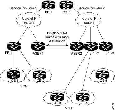
Figure 1 illustrates one MPLS VPN consisting of two separate autonomous systems. Each autonomous system operates under different administrative control and runs a different IGP. Service providers exchange routing information through EBGP border edge routers (ASBR1, ASBR2).
Figure 1 EBGP Connection Between Two MPLS VPN Inter-AS Systems with ASBRs Exchanging VPN-IPv4 Addresses
This configuration uses the following process to transmit information:
Step 1 ![]() The provider edge router (PE-1) assigns a label for a route before distributing that route. The PE router uses the multiprotocol extensions of BGP to transmit label mapping information. The PE router distributes the route as a VPN-IPv4 address. The address label and the VPN identifier are encoded as part of the NLRI.
The provider edge router (PE-1) assigns a label for a route before distributing that route. The PE router uses the multiprotocol extensions of BGP to transmit label mapping information. The PE router distributes the route as a VPN-IPv4 address. The address label and the VPN identifier are encoded as part of the NLRI.
Step 2 ![]() The two route reflectors (RR-1 and RR-2) reflect VPN-IPv4 internal routes within the autonomous system. The autonomous systems' border edge routers (ASBR1 and ASBR2) advertise the VPN-IPv4 external routes.
The two route reflectors (RR-1 and RR-2) reflect VPN-IPv4 internal routes within the autonomous system. The autonomous systems' border edge routers (ASBR1 and ASBR2) advertise the VPN-IPv4 external routes.
Step 3 ![]() The EBGP border edge router (ASBR1) redistributes the route to the next autonomous system (ASBR2). ASBR1 specifies its own address as the value of the EBGP next-hop attribute and assigns a new label. The address ensures the following:
The EBGP border edge router (ASBR1) redistributes the route to the next autonomous system (ASBR2). ASBR1 specifies its own address as the value of the EBGP next-hop attribute and assigns a new label. The address ensures the following:
•![]() That the next-hop router is always reachable in the service provider (P) backbone network.
That the next-hop router is always reachable in the service provider (P) backbone network.
•![]() That the label assigned by the distributing router is properly interpreted. (The label associated with a route must be assigned by the corresponding next-hop router.)
That the label assigned by the distributing router is properly interpreted. (The label associated with a route must be assigned by the corresponding next-hop router.)
Step 4 ![]() The EBGP border edge router (ASBR2) redistributes the route in one of the following ways, depending on its configuration:
The EBGP border edge router (ASBR2) redistributes the route in one of the following ways, depending on its configuration:
•![]() If the IBGP neighbors are configured with the neighbor next-hop-self command, ASBR2 changes the next-hop address of updates received from the EBGP peer, then forwards it.
If the IBGP neighbors are configured with the neighbor next-hop-self command, ASBR2 changes the next-hop address of updates received from the EBGP peer, then forwards it.
•![]() If the IBGP neighbors are not configured with the neighbor next-hop-self command, the next-hop address does not get changed. ASBR2 must propagate a host route for the EBGP peer through the IGP. To propagate the EBGP VPN-IPv4 neighbor host route, use the redistribute connected subnets command. The EBGP VPN-IPv4 neighbor host route is automatically installed in the routing table when the neighbor comes up. This is essential to establish the label switched path between PE routers in different autonomous systems.
If the IBGP neighbors are not configured with the neighbor next-hop-self command, the next-hop address does not get changed. ASBR2 must propagate a host route for the EBGP peer through the IGP. To propagate the EBGP VPN-IPv4 neighbor host route, use the redistribute connected subnets command. The EBGP VPN-IPv4 neighbor host route is automatically installed in the routing table when the neighbor comes up. This is essential to establish the label switched path between PE routers in different autonomous systems.
Exchange of VPN Routing Information in an MPLS VPN Inter-AS with ASBRs Exchanging VPN-IPv4 Addresses
Autonomous systems exchange VPN routing information (routes and labels) to establish connections. To control connections between autonomous systems, the PE routers and EBGP border edge routers maintain a Label Forwarding Information Base (LFIB). The LFIB manages the labels and routes that the PE routers and EBGP border edge routers receive during the exchange of VPN information.
Figure 2 illustrates the exchange of VPN route and label information between autonomous systems. The autonomous systems use the following conditions to exchange VPN routing information:
•![]() Routing information includes:
Routing information includes:
–![]() The destination network (N)
The destination network (N)
–![]() The next-hop field associated with the distributing router
The next-hop field associated with the distributing router
–![]() A local MPLS label (L)
A local MPLS label (L)
•![]() An RD1: route distinguisher is part of a destination network address. It makes the VPN-IPv4 route globally unique in the VPN service provider environment.
An RD1: route distinguisher is part of a destination network address. It makes the VPN-IPv4 route globally unique in the VPN service provider environment.
•![]() The ASBRs are configured to change the next-hop (next hop-self) when sending VPN-IPv4 NLRIs to the IBGP neighbors. Therefore, the ASBRs must allocate a new label when they forward the NLRI to the IBGP neighbors.
The ASBRs are configured to change the next-hop (next hop-self) when sending VPN-IPv4 NLRIs to the IBGP neighbors. Therefore, the ASBRs must allocate a new label when they forward the NLRI to the IBGP neighbors.
Figure 2 Exchanging Routes and Labels Between MPLS VPN Inter-AS Systems with ASBRs Exchanging VPN-IPv4 Addresses

Figure 3 illustrates the exchange of VPN route and label information between autonomous systems. The only difference is that ASBR2 is configured with the redistribute connected command, which propagates the host routes to all PEs. The redistribute connected command is necessary because ASBR2 is not configured to change the next-hop address.
Figure 3 Exchanging Routes and Labels with the redistribute connected Command in an MPLS VPN Inter-AS with ASBRs Exchanging VPN-IPv4 Addresses

Packet Forwarding Between MPLS VPN Inter-AS Systems with ASBRs Exchanging VPN-IPv4 Addresses
Figure 4 illustrates how packets are forwarded between autonomous systems in an interprovider network using the following packet forwarding method.
Packets are forwarded to their destination by means of MPLS. Packets use the routing information stored in the LFIB of each PE router and EBGP border edge router.
The service provider VPN backbone uses dynamic label switching to forward labels.
Each autonomous system uses standard multilevel labeling to forward packets between the edges of the autonomous system routers (for example, from CE-5 to PE-3). Between autonomous systems, only a single level of labeling is used, corresponding to the advertised route.
A data packet carries two levels of labels when traversing the VPN backbone:
•![]() The first label (IGP route label) directs the packet to the correct PE router or EBGP border edge router. (For example, the IGP label of ASBR2 points to the ASBR2 border edge router.)
The first label (IGP route label) directs the packet to the correct PE router or EBGP border edge router. (For example, the IGP label of ASBR2 points to the ASBR2 border edge router.)
•![]() The second label (VPN route label) directs the packet to the appropriate PE router or EBGP border edge router.
The second label (VPN route label) directs the packet to the appropriate PE router or EBGP border edge router.
Figure 4 Forwarding Packets Between MPLS VPN Inter-AS Systems with ASBRs Exchanging VPN-IPv4 Addresses

Figure 5 shows the same packet forwarding method as described in Figure 4, except the EBGP router (ASBR1) forwards the packet without reassigning it a new label.
Figure 5 Forwarding Packets Without a New Label Assignment Between MPLS VPN Inter-AS Systems with ASBRs Exchanging VPN-IPv4 Addresses

Use of a Confederation for MPLS VPN Inter-AS with ASBRs Exchanging VPN-IPv4 Addresses
A confederation is multiple subautonomous systems grouped together. A confederation reduces the total number of peer devices in an autonomous system. A confederation divides an autonomous system into subautonomous systems and assigns a confederation identifier to the autonomous systems. A VPN can span service providers running in separate autonomous systems or in multiple subautonomous systems that form a confederation.
In a confederation, each subautonomous system is fully meshed with other subautonomous systems. The subautonomous systems communicate using an IGP, such as Open Shortest Path First (OSPF) or Intermediate System-to-Intermediate System (IS-IS). Each subautonomous system also has an EBGP connection to the other subautonomous systems. The confederation EBGP (CEBGP) border edge routers forward next-hop-self addresses between the specified subautonomous systems. The next-hop-self address forces the BGP to use a specified address as the next hop rather than letting the protocol choose the next hop.
You can configure a confederation with separate subautonomous systems in either of two ways:
•![]() You can configure a router to forward next-hop-self addresses between only the CEBGP border edge routers (both directions). The subautonomous systems (IBGP peers) at the subautonomous system border do not forward the next-hop-self address. Each subautonomous system runs as a single IGP domain. However, the CEBGP border edge router addresses are known in the IGP domains.
You can configure a router to forward next-hop-self addresses between only the CEBGP border edge routers (both directions). The subautonomous systems (IBGP peers) at the subautonomous system border do not forward the next-hop-self address. Each subautonomous system runs as a single IGP domain. However, the CEBGP border edge router addresses are known in the IGP domains.
•![]() You can configure a router to forward next-hop-self addresses between the CEBGP border edge routers (both directions) and within the IBGP peers at the subautonomous system border. Each subautonomous system runs as a single IGP domain but also forwards next-hop-self addresses between the PE routers in the domain. The CEBGP border edge router addresses are known in the IGP domains.
You can configure a router to forward next-hop-self addresses between the CEBGP border edge routers (both directions) and within the IBGP peers at the subautonomous system border. Each subautonomous system runs as a single IGP domain but also forwards next-hop-self addresses between the PE routers in the domain. The CEBGP border edge router addresses are known in the IGP domains.

Note ![]() Figure 2 and Figure 3 illustrate how two autonomous systems exchange routes and forward packets. Subautonomous systems in a confederation use a similar method of exchanging routes and forwarding packets.
Figure 2 and Figure 3 illustrate how two autonomous systems exchange routes and forward packets. Subautonomous systems in a confederation use a similar method of exchanging routes and forwarding packets.
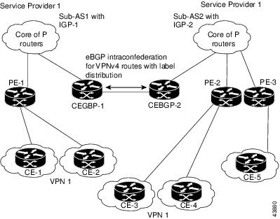
Figure 6 illustrates a typical MPLS VPN confederation configuration. In this confederation configuration:
•![]() The two CEBGP border edge routers exchange VPN-IPv4 addresses with labels between the two subautonomous systems.
The two CEBGP border edge routers exchange VPN-IPv4 addresses with labels between the two subautonomous systems.
•![]() The distributing router changes the next-hop addresses and labels and uses a next-hop-self address.
The distributing router changes the next-hop addresses and labels and uses a next-hop-self address.
•![]() IGP-1 and IGP-2 know the addresses of CEBGP-1 and CEBGP-2.
IGP-1 and IGP-2 know the addresses of CEBGP-1 and CEBGP-2.
Figure 6 EBGP Connection Between Two Subautonomous Systems in a Confederation
In this confederation configuration:
•![]() CEBGP border edge routers function as neighboring peers between the subautonomous systems. The subautonomous systems use EBGP to exchange route information.
CEBGP border edge routers function as neighboring peers between the subautonomous systems. The subautonomous systems use EBGP to exchange route information.
•![]() Each CEBGP border edge router (CEBGP-1, CEBGP-2) assigns a label for the route before distributing the route to the next subautonomous system. The CEBGP border edge router distributes the route as a VPN-IPv4 address by using the multiprotocol extensions of BGP. The label and the VPN identifier are encoded as part of the NLRI.
Each CEBGP border edge router (CEBGP-1, CEBGP-2) assigns a label for the route before distributing the route to the next subautonomous system. The CEBGP border edge router distributes the route as a VPN-IPv4 address by using the multiprotocol extensions of BGP. The label and the VPN identifier are encoded as part of the NLRI.
•![]() Each PE and CEBGP border edge router assigns its own label to each VPN-IPv4 address prefix before redistributing the routes. The CEBGP border edge routers exchange VPN-IPv4 addresses with the labels. The next-hop-self address is included in the label (as the value of the EBGP next-hop attribute). Within the subautonomous systems, the CEBGP border edge router address is distributed throughout the IBGP neighbors, and the two CEBGP border edge routers are known to both confederations.
Each PE and CEBGP border edge router assigns its own label to each VPN-IPv4 address prefix before redistributing the routes. The CEBGP border edge routers exchange VPN-IPv4 addresses with the labels. The next-hop-self address is included in the label (as the value of the EBGP next-hop attribute). Within the subautonomous systems, the CEBGP border edge router address is distributed throughout the IBGP neighbors, and the two CEBGP border edge routers are known to both confederations.
How to Configure MPLS VPN Inter-AS with ASBRs Exchanging VPN-IPv4 Addresses
To configure MPLS VPN Inter-AS with ASBRs Exchanging VPN-IPv4 Addresses, perform the tasks in the following sections:
•![]() Configuring the ASBRs to Exchange VPN-IPv4 Addresses (required)
Configuring the ASBRs to Exchange VPN-IPv4 Addresses (required)
•![]() Configuring EBGP Routing to Exchange VPN Routes Between Subautonomous Systems in a Confederation (required)
Configuring EBGP Routing to Exchange VPN Routes Between Subautonomous Systems in a Confederation (required)
•![]() Verifying Inter-AS with ASBRs Exchanging VPN-IPv4 Addresses (optional)
Verifying Inter-AS with ASBRs Exchanging VPN-IPv4 Addresses (optional)
Configuring the ASBRs to Exchange VPN-IPv4 Addresses
To configure an EBGP ASBR to exchange VPN-IPv4 routes with another autonomous system, perform this task.
Note ![]() Issue the redistribute connected subnets command in the IGP configuration portion of the router to propagate host routes for VPN-IPv4 EBGP neighbors to other routers and provider edge routers. Alternatively, you can specify the next-hop-self address when you configure IBGP neighbors.
Issue the redistribute connected subnets command in the IGP configuration portion of the router to propagate host routes for VPN-IPv4 EBGP neighbors to other routers and provider edge routers. Alternatively, you can specify the next-hop-self address when you configure IBGP neighbors.
SUMMARY STEPS
1. ![]() enable
enable
2. ![]() configure terminal
configure terminal
3. ![]() router bgp as-number
router bgp as-number
4. ![]() no bgp default route-target filter
no bgp default route-target filter
5. ![]() address-family vpnv4 [unicast]
address-family vpnv4 [unicast]
6. ![]() neighbor peer-group-name remote-as as-number
neighbor peer-group-name remote-as as-number
7. ![]() neighbor peer-group-name activate
neighbor peer-group-name activate
8. ![]() exit-address-family
exit-address-family
9. ![]() end
end
DETAILED STEPS
Configuring EBGP Routing to Exchange VPN Routes Between Subautonomous Systems in a Confederation
Perform this task to configure EBGP routing to exchange VPN routes between subautonomous systems in a confederation.
Note ![]() To ensure that the host routes for VPN-IPv4 EBGP neighbors are propagated (by means of the IGP) to the other routers and provider edge routers, specify the redistribute connected command in the IGP configuration portion of the CEBGP router. If you are using OSPF, make sure that the OSPF process is not enabled on the CEBGP interface where the "redistribute connected" subnet exists.
To ensure that the host routes for VPN-IPv4 EBGP neighbors are propagated (by means of the IGP) to the other routers and provider edge routers, specify the redistribute connected command in the IGP configuration portion of the CEBGP router. If you are using OSPF, make sure that the OSPF process is not enabled on the CEBGP interface where the "redistribute connected" subnet exists.
Note ![]() In this confederation, subautonomous system IGP domains must know the addresses of CEBGP-1 and CEBGP-2. If you do not specify a next-hop-self address as part of the router configuration, ensure that the addresses of all PE routers in the subautonomous system are distributed throughout the network, not just the addresses of CEBGP-1 and CEBGP-2.
In this confederation, subautonomous system IGP domains must know the addresses of CEBGP-1 and CEBGP-2. If you do not specify a next-hop-self address as part of the router configuration, ensure that the addresses of all PE routers in the subautonomous system are distributed throughout the network, not just the addresses of CEBGP-1 and CEBGP-2.
SUMMARY STEPS
1. ![]() enable
enable
2. ![]() configure terminal
configure terminal
3. ![]() router bgp sub-autonomous-system
router bgp sub-autonomous-system
4. ![]() bgp confederation identifier as-number
bgp confederation identifier as-number
5. ![]() bgp confederation peers sub-autonomous-system
bgp confederation peers sub-autonomous-system
6. ![]() no bgp default route-target filter
no bgp default route-target filter
7. ![]() address-family vpnv4 [unicast]
address-family vpnv4 [unicast]
8. ![]() neighbor peer-group-name remote-as as-number
neighbor peer-group-name remote-as as-number
9. ![]() neighbor peer-group-name next-hop-self
neighbor peer-group-name next-hop-self
10. ![]() neighbor peer-group-name activate
neighbor peer-group-name activate
11. ![]() exit-address-family
exit-address-family
12. ![]() end
end
DETAILED STEPS
Verifying Inter-AS with ASBRs Exchanging VPN-IPv4 Addresses
Perform this task to display the VPN-IPv4 LFIB entries.
SUMMARY STEPS
1. ![]() enable
enable
2. ![]() show ip bgp vpnv4 {all | rd route-distinguisher | vrf vrf-name} [summary] [labels]
show ip bgp vpnv4 {all | rd route-distinguisher | vrf vrf-name} [summary] [labels]
3. ![]() show mpls forwarding-table [network {mask | length} | labels label [-label] | interface interface | next-hop address | lsp-tunnel [tunnel-id]] [vrf vrf-name] [detail]
show mpls forwarding-table [network {mask | length} | labels label [-label] | interface interface | next-hop address | lsp-tunnel [tunnel-id]] [vrf vrf-name] [detail]
4. ![]() disable
disable
DETAILED STEPS
Examples
The sample output from the show mpls forwarding-table command shows how the VPN-IPv4 LFIB entries appear:
Router# show mpls forwarding-table
Local Outgoing Prefix Bytes tag Outgoing Next Hop
tag tag or VC or Tunnel Id switched interface
33 33 10.120.4.0/24 0 Hs0/0 point2point
35 27 100:12:10.200.0.1/32 \
0 Hs0/0 point2point
In this example, the Prefix field appears as a VPN-IPv4 RD, plus the prefix. If the value is longer than the width of the Prefix column (as illustrated in the last line of the example), the output automatically wraps onto the next line in the forwarding table, preserving column alignment.
Configuration Examples for MPLS VPN Inter-AS with ASBRs Exchanging VPN-IPv4 Addresses
This section provides the following configuration examples for MPLS VPN Inter-AS:
•![]() Configuring MPLS VPN Inter-AS with ASBRs Exchanging VPN-IPv4 Addresses: Example
Configuring MPLS VPN Inter-AS with ASBRs Exchanging VPN-IPv4 Addresses: Example
•![]() Configuring MPLS VPN Inter-AS with ASBRs Exchanging VPN-IPv4 Addresses in a Confederation: Example
Configuring MPLS VPN Inter-AS with ASBRs Exchanging VPN-IPv4 Addresses in a Confederation: Example
Configuring MPLS VPN Inter-AS with ASBRs Exchanging VPN-IPv4 Addresses: Example
The network topology in Figure 7 shows two autonomous systems, which are configured as follows:
•![]() Autonomous system 1 (AS1) includes PE1, P1, and EBGP1. The IGP is OSPF.
Autonomous system 1 (AS1) includes PE1, P1, and EBGP1. The IGP is OSPF.
•![]() Autonomous system 2 (AS2) includes PE2, P2, and EBGP2. The IGP is IS-IS.
Autonomous system 2 (AS2) includes PE2, P2, and EBGP2. The IGP is IS-IS.
•![]() CE1 and CE2 belong to the same VPN, which is called VPN1.
CE1 and CE2 belong to the same VPN, which is called VPN1.
•![]() The P routers are route reflectors.
The P routers are route reflectors.
•![]() EBGP1 is configured with the redistribute connected subnets command.
EBGP1 is configured with the redistribute connected subnets command.
•![]() EBGP2 is configured with the neighbor next-hop-self command.
EBGP2 is configured with the neighbor next-hop-self command.
Figure 7 Configuring Two Autonomous Systems

Configuration for Autonomous System 1, CE1: Example
The following example shows how to configure CE1 in VPN1 in a topology with two autonomous systems (see Figure 7):
CE1: Burlington
!
interface Loopback1
ip address aa.0.0.6 255.255.255.255
!
interface Serial1/3
description wychmere
no ip address
encapsulation frame-relay
frame-relay intf-type dce
!
interface Serial1/3.1 point-to-point
description wychmere
ip address aa.6.2.1 255.255.255.252
frame-relay interface-dlci 22
!
router ospf 1
network aa.0.0.0 0.255.255.255 area 0
Configuration for Autonomous System 1, PE1: Example
The following example shows how to configure PE1 in AS1 in a topology with two autonomous systems (see Figure 7):
PE1: wychmere
!
ip cef
!
ip vrf V1
rd 1:105
route-target export 1:100
route-target import 1:100
!
interface Serial0/0
description Burlington
no ip address
encapsulation frame-relay
no fair-queue
clockrate 2000000
!
interface Serial0/0.3 point-to-point
description Burlington
ip vrf forwarding V1
ip address aa.6.2.2 255.255.255.252
frame-relay interface-dlci 22
!
interface Ethernet0/1
description Vermont
ip address aa.2.2.5 255.255.255.0
tag-switching ip
!
router ospf 1
log-adjacency-changes
network aa.0.0.0 0.255.255.255 area 0
!
router ospf 10 vrf V1
log-adjacency-changes
redistribute bgp 1 metric 100 subnets
network aa.0.0.0 0.255.255.255 area 0
!
router bgp 1
no synchronization
neighbor 1 peer-group
neighbor 1 remote-as 1
neighbor 1 update-source Loopback0
neighbor aa.0.0.2 peer-group R
no auto-summary
!
address-family ipv4 vrf V1
redistribute ospf 10
no auto-summary
no synchronization
exit-address-family
!
address-family vpnv4
neighbor R activate
neighbor R send-community extended
neighbor aa.0.0.2 peer-group R
no auto-summary
exit-address-family
Configuration for Autonomous System 1, P1: Example
The following example shows how to configure P1 in AS1 in a topology with two autonomous systems (see Figure 7):
P1: Vermont
!
ip cef
!
interface Loopback0
ip address aa.0.0.2 255.255.255.255
!
interface Ethernet0/1
description Ogunquit
ip address aa.2.1.1 255.255.255.0
tag-switching ip
!
interface FastEthernet2/0
description wychmere
ip address aa.2.2.1 255.255.255.0
duplex auto
speed auto
tag-switching ip
!
router ospf 1
log-adjacency-changes
network aa.0.0.0 0.255.255.255 area 0
!
router bgp 1
no synchronization
bgp log-neighbor-changes
neighbor R peer-group
neighbor R remote-as 1
neighbor R update-source Loopback0
neighbor R route-reflector-client
neighbor aa.0.0.4 peer-group R
neighbor aa.0.0.5 peer-group R
!
address-family vpnv4
neighbor R activate
neighbor R route-reflector-client
neighbor R send-community extended
neighbor aa.0.0.4 peer-group R
neighbor aa.0.0.5 peer-group R
exit-address-family
Configuration for Autonomous System 1, EBGP1: Example
The following example shows how to configure EBGP1 in AS1 in a topology with two autonomous systems (see Figure 7):
EBGP1: Ogunquit
!
ip cef
!
interface Loopback0
ip address aa.0.0.4 255.255.255.255
!
EBGP1: Ogunquit
!
ip cef
!
interface Loopback0
ip address aa.0.0.4 255.255.255.255
!
interface Ethernet0/1
description Vermont
ip address aa.2.1.40 255.255.255.0
tag-switching ip
!
interface ATM1/0
description Lowell
no ip address
no atm scrambling cell-payload
no atm ilmi-keepalive
!
interface ATM1/0.1 point-to-point
description Lowell
ip address aa.0.0.1 255.255.255.252
pvc 1/100
!
router ospf 1
log-adjacency-changes
redistribute connected subnets
network aa.0.0.0 0.255.255.255 area 0
!
router bgp 1
no synchronization
no bgp default route-target filter
bgp log-neighbor-changes
neighbor R peer-group
neighbor R remote-as 1
neighbor R update-source Loopback0
neighbor aa.0.0.2 remote-as 2
neighbor aa.0.0.2 peer-group R
no auto-summary
!
address-family vpnv4
neighbor R activate
neighbor R send-community extended
neighbor aa.0.0.2 activate
neighbor aa.0.0.2 send-community extended
neighbor aa.0.0.2 peer-group R
no auto-summary
exit-address-family
Configuration for Autonomous System 2, EBGP2: Example
The following example shows how to configure EBGP2 in AS2 in a topology with two autonomous systems (see Figure 7):
EBGP2: Lowell
!
ip cef
!
ip vrf V1
rd 2:103
route-target export 1:100
route-target import 1:100
!
interface Loopback0
ip address aa.0.0.3 255.255.255.255
ip router isis
!
interface Loopback1
ip vrf forwarding V1
ip address aa.0.0.3 255.255.255.255
!
interface Serial0/0
description Littleton
no ip address
encapsulation frame-relay
load-interval 30
no fair-queue
clockrate 2000000
!
interface Serial0/0.2 point-to-point
description Littleton
ip unnumbered Loopback0
ip router isis
tag-switching ip
frame-relay interface-dlci 23
!
interface ATM1/0
description Ogunquit
no ip address
atm clock INTERNAL
no atm scrambling cell-payload
no atm ilmi-keepalive
!
interface ATM1/0.1 point-to-point
description Ogunquit
ip address aa.0.0.2 255.255.255.252
pvc 1/100
!
router isis
net 49.0002.0000.0000.0003.00
!
router bgp 2
no synchronization
no bgp default route-target filter
bgp log-neighbor-changes
neighbor aa.0.0.1 remote-as 1
neighbor aa.0.0.8 remote-as 2
neighbor aa.0.0.8 update-source Loopback0
neighbor aa.0.0.8 next-hop-self
!
address-family ipv4 vrf V1
redistribute connected
no auto-summary
no synchronization
exit-address-family
!
address-family vpnv4
neighbor aa.0.0.1 activate
neighbor aa.0.0.1 send-community extended
neighbor aa.0.0.8 activate
neighbor aa.0.0.8 next-hop-self
neighbor aa.0.0.8 send-community extended
exit-address-family
Configuration for Autonomous System 2, P2: Example
The following example shows how to configure P2 in AS2 in a topology with two autonomous systems (see Figure 7):
P2: Littleton
!
ip cef
!
ip vrf V1
rd 2:108
route-target export 1:100
route-target import 1:100
!
interface Loopback0
ip address aa.0.0.8 255.255.255.255
ip router isis
!
interface Loopback1
ip vrf forwarding V1
ip address aa.0.0.8 255.255.255.255
!
interface FastEthernet0/0
description Pax
ip address aa.9.1.2 255.255.255.0
ip router isis
tag-switching ip
!
interface Serial5/0
description Lowell
no ip address
encapsulation frame-relay
frame-relay intf-type dce
!
interface Serial5/0.1 point-to-point
description Lowell
ip unnumbered Loopback0
ip router isis
tag-switching ip
frame-relay interface-dlci 23
!
router isis
net aa.0002.0000.0000.0008.00
!
router bgp 2
no synchronization
bgp log-neighbor-changes
neighbor R peer-group
neighbor R remote-as 2
neighbor R update-source Loopback0
neighbor R route-reflector-client
neighbor aa.0.0.3 peer-group R
neighbor aa.0.0.9 peer-group R
!
address-family ipv4 vrf V1
redistribute connected
no auto-summary
no synchronization
exit-address-family
!
address-family vpnv4
neighbor R activate
neighbor R route-reflector-client
neighbor R send-community extended
neighbor aa.0.0.3 peer-group R
neighbor aa.0.0.9 peer-group R
exit-address-family
Configuration for Autonomous System 2, PE2: Example
The following example shows how to configure PE2 in AS2 in a topology with two autonomous systems (see Figure 7):
PE2: Pax
!
ip cef
!
ip vrf V1
rd 2:109
route-target export 1:100
route-target import 1:100
!
interface Loopback0
ip address aa.0.0.9 255.255.255.255
ip router isis
!
interface Loopback1
ip vrf forwarding V1
ip address aa.0.0.9 255.255.255.255
!
interface Serial0/0
description Bethel
no ip address
encapsulation frame-relay
frame-relay intf-type dce
no fair-queue
clockrate 2000000
!
interface Serial0/0.1 point-to-point
description Bethel
ip vrf forwarding V1
ip unnumbered Loopback1
frame-relay interface-dlci 24
!
interface FastEthernet0/1
description Littleton
ip address aa.9.1.1 255.255.255.0
ip router isis
tag-switching ip
!
router ospf 10 vrf V1
log-adjacency-changes
redistribute bgp 2 subnets
network aa.0.0.0 0.255.255.255 area 0
!
router isis
net 49.0002.0000.0000.0009.00
!
router bgp 2
no synchronization
bgp log-neighbor-changes
neighbor aa.0.0.8 remote-as 2
neighbor aa.0.0.8 update-source Loopback0
!
address-family ipv4 vrf V1
redistribute connected
redistribute ospf 10
no auto-summary
no synchronization
exit-address-family
!
address-family vpnv4
neighbor aa.0.0.8 activate
neighbor aa.0.0.8 send-community extended
exit-address-family v
Configuration for Autonomous System 2, CE2: Example
The following example shows how to configure CE2 in VPN1 in a topology with two autonomous systems (see Figure 7):
CE2: Bethel
!
interface Loopback0
ip address 1.0.0.11 255.255.255.255
!
interface Serial0
description Pax
no ip address
encapsulation frame-relay
no fair-queue
clockrate 2000000
!
interface Serial0.1 point-to-point
description Pax
ip unnumbered Loopback0
frame-relay interface-dlci 24
!
router ospf 1
network aa.0.0.0 0.255.255.255 area 0
Configuring MPLS VPN Inter-AS with ASBRs Exchanging VPN-IPv4 Addresses in a Confederation: Example
The network topology in Figure 8 shows a single internet service provider, which is partitioning the backbone with confederations. The autonomous system number of the provider is 100. The two autonomous systems run their own IGPs and are configured as follows:
•![]() Autonomous system 1 (AS1) includes PE1, P1, ASBR1. The IGP is OSPF.
Autonomous system 1 (AS1) includes PE1, P1, ASBR1. The IGP is OSPF.
•![]() Autonomous system 2 (AS2) includes PE2, P2, ASBR2. The IGP is IS-IS.
Autonomous system 2 (AS2) includes PE2, P2, ASBR2. The IGP is IS-IS.
•![]() CE1 and CE2 belong to the same VPN, which is called VPN1.
CE1 and CE2 belong to the same VPN, which is called VPN1.
•![]() The P routers are route reflectors.
The P routers are route reflectors.
•![]() ASBR1 is configured with the redistribute connected subnets command.
ASBR1 is configured with the redistribute connected subnets command.
•![]() ASBR2 is configured with the neighbor next-hop-self command.
ASBR2 is configured with the neighbor next-hop-self command.
Figure 8 Configuring Two Autonomous Systems in a Confederation

Configuration for Autonomous System 1, CE1: Example
The following example shows how to configure CE1 in VPN1 in a confederation topology (see Figure 8):
CE1: Burlington
!
interface Loopback1
ip address aa.0.0.6 255.255.255.255
!
interface Serial1/3
description wychmere
no ip address
encapsulation frame-relay
frame-relay intf-type dce
!
interface Serial1/3.1 point-to-point
description wychmere
ip address aa.6.2.1 255.255.255.252
frame-relay interface-dlci 22
!
router ospf 1
network aa.0.0.0 0.255.255.255 area 0
Configuration for Autonomous System 1, PE1: Example
The following example shows how to configure PE1 in AS1 in a confederation topology (see Figure 8):
PE1: wychmere
!
ip cef
!
ip vrf V1
rd 1:105
route-target export 1:100
route-target import 1:100
!
interface Serial0/0
description Burlington
no ip address
encapsulation frame-relay
no fair-queue
clockrate 2000000
!
interface Serial0/0.3 point-to-point
description Burlington
ip vrf forwarding V1
ip address aa.6.2.2 255.255.255.252
frame-relay interface-dlci 22
!
interface Ethernet0/1
description Vermont
ip address aa.2.2.5 255.255.255.0
tag-switching ip
!
router ospf 1
log-adjacency-changes
network aa.0.0.0 0.255.255.255 area 0
!
router ospf 10 vrf V1
log-adjacency-changes
redistribute bgp 1 metric 100 subnets
network aa.0.0.0 0.255.255.255 area 0
!
router bgp 1
no synchronization
bgp confederation identifier 100
bgp confederation identifier 100
neighbor 1 peer-group
neighbor 1 remote-as 1
neighbor 1 update-source Loopback0
neighbor aa.0.0.2 peer-group R
no auto-summary
!
address-family ipv4 vrf V1
redistribute ospf 10
no auto-summary
no synchronization
exit-address-family
!
address-family vpnv4
neighbor R activate
neighbor R send-community extended
neighbor aa.0.0.2 peer-group R
no auto-summary
exit-address-family
Configuration for Autonomous System 1, P1 Example
The following example shows how to configure P1 in AS1 in a confederation topology (see Figure 8):
P1: Vermont
!
ip cef
!
interface Loopback0
ip address aa.0.0.2 255.255.255.255
!
interface Ethernet0/1
description Ogunquit
ip address 100.2.1.1 255.255.255.0
tag-switching ip
!
interface FastEthernet2/0
description wychmere
ip address aa.2.2.1 255.255.255.0
duplex auto
speed auto
tag-switching ip
!
router ospf 1
log-adjacency-changes
network aa.0.0.0 0.255.255.255 area 0
!
router bgp 1
no synchronization
bgp log-neighbor-changes
bgp confederation identifier 100
neighbor R peer-group
neighbor R remote-as 1
neighbor R update-source Loopback0
neighbor R route-reflector-client
neighbor 100.0.0.4 peer-group R
neighbor 100.0.0.5 peer-group R
!
address-family vpnv4
neighbor R activate
neighbor R route-reflector-client
neighbor R send-community extended
neighbor aa.0.0.4 peer-group R
neighbor aa.0.0.5 peer-group R
exit-address-family
Configuration for Autonomous System 1, ASBR1: Example
The following example shows how to configure ASBR1 in AS1 in a confederation topology (see Figure 8):
EBGP1: Ogunquit
!
ip cef
!
interface Loopback0
ip address aa.0.0.4 255.255.255.255
!
interface Ethernet0/1
description Vermont
ip address aa.2.1.40 255.255.255.0
tag-switching ip
!
interface ATM1/0
description Lowell
no ip address
no atm scrambling cell-payload
no atm ilmi-keepalive
!
interface ATM1/0.1 point-to-point
description Lowell
ip address aa.0.0.1 255.255.255.252
pvc 1/100
!
router ospf 1
log-adjacency-changes
redistribute connected subnets
network aa.0.0.0 0.255.255.255 area 0
!
router bgp 1
no synchronization
no bgp default route-target filter
bgp log-neighbor-changes
bgp confederation identifier 100
bgp confederation peers 1
neighbor R peer-group
neighbor R remote-as 1
neighbor R update-source Loopback0
neighbor aa.0.0.2 remote-as 2
neighbor aa.0.0.2 next-hop-self
neighbor aa.0.0.2 peer-group R
no auto-summary
!
address-family vpnv4
neighbor R activate
neighbor R send-community extended
neighbor aa.0.0.2 activate
neighbor aa.0.0.2 next-hop-self
neighbor aa.0.0.2 send-community extended
neighbor aa.0.0.2 peer-group R
no auto-summary
exit-address-family
Configuration for Autonomous System 2, ASBR2: Example
The following example shows how to configure ASBR2 in AS2 in a confederation topology (see Figure 8):
EBGP2: Lowell
!
ip cef
!
ip vrf V1
rd 2:103
route-target export 1:100
route-target import 1:100
!
interface Loopback0
ip address aa.0.0.3 255.255.255.255
ip router isis
!
interface Loopback1
ip vrf forwarding V1
ip address aa.0.0.3 255.255.255.255
!
interface Serial0/0
description Littleton
no ip address
encapsulation frame-relay
load-interval 30
no fair-queue
clockrate 2000000
!
interface Serial0/0.2 point-to-point
description Littleton
ip unnumbered Loopback0
ip router isis
tag-switching ip
frame-relay interface-dlci 23
!
interface ATM1/0
description Ogunquit
no ip address
atm clock INTERNAL
no atm scrambling cell-payload
no atm ilmi-keepalive
!
interface ATM1/0.1 point-to-point
description Ogunquit
ip address aa.0.0.2 255.255.255.252
pvc 1/100
!
router isis
net aa.0002.0000.0000.0003.00
!
router bgp 2
no synchronization
no bgp default route-target filter
bgp log-neighbor-changes
bgp confederation identifier 100
bgp confederation peers 1
neighbor aa.0.0.1 remote-as 1
neighbor aa.0.0.1 next-hop-self
neighbor aa.0.0.8 remote-as 2
neighbor aa.0.0.8 update-source Loopback0
neighbor aa.0.0.8 next-hop-self
!
address-family ipv4 vrf V1
redistribute connected
no auto-summary
no synchronization
exit-address-family
!
address-family vpnv4
neighbor aa.0.0.1 activate
neighbor aa.0.0.1 next-hop-self
neighbor aa.0.0.1 send-community extended
neighbor aa.0.0.8 activate
neighbor aa.0.0.8 next-hop-self
neighbor aa.0.0.8 send-community extended
exit-address-family
Configuration for Autonomous System 2, P2: Example
The following example shows how to configure P2 in AS2 in a confederation topology (see Figure 8):
P2: Littleton
!
ip cef
!
ip vrf V1
rd 2:108
route-target export 1:100
route-target import 1:100
!
interface Loopback0
ip address aa.0.0.8 255.255.255.255
ip router isis
!
interface Loopback1
ip vrf forwarding V1
ip address aa.0.0.8 255.255.255.255
!
interface FastEthernet0/0
description Pax
ip address aa.9.1.2 255.255.255.0
ip router isis
tag-switching ip
!
interface Serial5/0
description Lowell
no ip address
encapsulation frame-relay
frame-relay intf-type dce
!
interface Serial5/0.1 point-to-point
description Lowell
ip unnumbered Loopback0
ip router isis
tag-switching ip
frame-relay interface-dlci 23
!
router isis
net aa.0002.0000.0000.0008.00
!
router bgp 2
no synchronization
bgp log-neighbor-changes
bgp confederation identifier 100
neighbor R peer-group
neighbor R remote-as 2
neighbor R update-source Loopback0
neighbor R route-reflector-client
neighbor aa.0.0.3 peer-group R
neighbor aa.0.0.9 peer-group R
!
address-family ipv4 vrf V1
redistribute connected
no auto-summary
no synchronization
exit-address-family
!
address-family vpnv4
neighbor R activate
neighbor R route-reflector-client
neighbor R send-community extended
neighbor aa.0.0.3 peer-group R
neighbor aa.0.0.9 peer-group R
exit-address-family
Configuration for Autonomous System 2, PE2: Example
The following example shows how to configure PE2 in AS2 in a confederation topology (see Figure 8):
PE2: Pax
!
ip cef
!
ip vrf V1
rd 2:109
route-target export 1:100
route-target import 1:100
!
interface Loopback0
ip address aa.0.0.9 255.255.255.255
ip router isis
!
interface Loopback1
ip vrf forwarding V1
ip address 1.0.0.9 255.255.255.255
!
interface Serial0/0
description Bethel
no ip address
encapsulation frame-relay
frame-relay intf-type dce
no fair-queue
clockrate 2000000
!
interface Serial0/0.1 point-to-point
description Bethel
ip vrf forwarding V1
ip unnumbered Loopback1
frame-relay interface-dlci 24
!
interface FastEthernet0/1
description Littleton
ip address 200.9.1.1 255.255.255.0
ip router isis
tag-switching ip
!
router ospf 10 vrf V1
log-adjacency-changes
redistribute bgp 2 subnets
network aa.0.0.0 0.255.255.255 area 0
!
router isis
net aa.0002.0000.0000.0009.00
!
router bgp 2
no synchronization
bgp log-neighbor-changes
bgp confederation identifier 100
neighbor aa.0.0.8 remote-as 2
neighbor aa.0.0.8 update-source Loopback0
!
address-family ipv4 vrf V1
redistribute connected
redistribute ospf 10
no auto-summary
no synchronization
exit-address-family
!
address-family vpnv4
neighbor aa.0.0.8 activate
neighbor aa.0.0.8 send-community extended
exit-address-family
Configuration for Autonomous System 2, CE2: Example
The following example shows how to configure CE2 in VPN1 in a confederation topology (see
Figure 8):
CE2: Bethel
!
interface Loopback0
ip address aa.0.0.11 255.255.255.255
!
interface Serial0
description Pax
no ip address
encapsulation frame-relay
no fair-queue
clockrate 2000000
!
interface Serial0.1 point-to-point
description Pax
ip unnumbered Loopback0
frame-relay interface-dlci 24
!
router ospf 1
network aa.0.0.0 0.255.255.255 area 0
Command Reference
This feature uses no new or modified commands.
Additional References
The following sections provide references related to MPLS VPNs.
Related Documents
|
|
|
|---|---|
MPLS |
Standards
|
|
|
|---|---|
No new or modified standards are supported by this feature, and support for existing standards has not been modified by this feature. |
— |
MIBs
RFCs
Technical Assistance
Feature Information for MPLS VPN Inter-AS with ASBRs Exchanging VPN-IPv4 Addresses
Table 2 lists the release history for this feature.
Not all commands may be available in your Cisco IOS software release. For details on when support for specific commands was introduced, see the command reference documents.
Use Cisco Feature Navigator to find information about platform support and software image support. Cisco Feature Navigator enables you to determine which Cisco IOS and Catalyst OS software images support a specific software release, feature set, or platform. To access Cisco Feature Navigator, go to http://www.cisco.com/go/cfn. An account on Cisco.com is not required.
Note ![]() Table 2 lists only the Cisco IOS software release that introduced support for a given feature in a given Cisco IOS software release train. Unless noted otherwise, subsequent releases of that Cisco IOS software release train also support that feature.
Table 2 lists only the Cisco IOS software release that introduced support for a given feature in a given Cisco IOS software release train. Unless noted otherwise, subsequent releases of that Cisco IOS software release train also support that feature.
 Feedback