Overview

This chapter provides an overview of the Cisco NCS 2002, NCS 2006, and NCS 2015 shelf install.


Note


The Cisco NCS shelf assemblies are intended for use with telecommunications equipment only.

The sections are:

Compliance Standards

Install the NCS 2002, NCS 2006, and NCS 2015 shelves in compliance with your local and national electrical codes:

  • United States: National Fire Protection Association (NFPA) 70; United States National Electrical Code.
  • Canada: Canadian Electrical Code, Part I, CSA C22.1.
  • Other countries: If local and national electrical codes, are not available, refer to IEC 364, Part 1 through Part 7.

Safety Labels

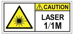
Cisco NCS 2000 Series chassis is classified as Hazard Level 1M as per IEC 60825-2 and Laser Class 1M as per IEC 60825-1, since it may include embedded or pluggable optical modules Class 1 or Class 1M.

The Class 1/1M Laser Product label is shown in the following figure.

Figure 1. Class 1/1M Laser Product Label
Class 1/1M Laser Product Label

This section explains the significance of the safety labels attached to the NCS 2002, NCS 2006, and NCS 2015 chassis. The faceplates of the chassis are clearly labeled with warnings about the laser radiation levels.

You must understand all warning labels before working on the chassis.

Figure 2. Class 1M Laser Product Label
Class 1M Laser Product Label

Safety Precaution for Module Installation and Removal

Ensure to observe the following safety precautions when you are working with the chassis modules.

Invisible laser radiations present. Statement 1016

Invisible laser radiation may be emitted from disconnected fibers or connectors. Do not stare into beams or view directly with optical instruments. Statement 1051

Figure 3. Class 1/1M Laser Product Label
Class 1/1M Laser Product Label

Safety Precaution for Laser Radiation

Cisco NCS 2000 Series chassis is classified as Hazard Level 1M as per IEC 60825-2 and Laser Class 1M as per IEC 60825-1, since it may include embedded or pluggable optical modules Class 1 or Class 1M.

Figure 4. Class 1M Laser Product Label
Class 1M Laser Product Label

Cisco NCS 2002 Shelf

The NCS 2002 is designed to comply with Telcordia GR-1089-CORE, Issue 5. The NCS 2002 provides only Type 2 and Type 4 interfaces. A single NCS 2002 shelf supports both ANSI and ETSI standards.

The NCS 2002 is Federal Information Processing Standard (FIPS) 140-2 and Common Criteria (CC) compliant.

The NCS 2002 shelf has 3 horizontal card slots —Slot 1, Slot 2, and Slot 3. While Slot 2 and Slot 3 house MSTP cards that provide 10 to 100 Gbps interconnections, Slot 1 accommodates the TNC, TNCE, TSC, or TSCE card (timing and control card). The NCS 2002 system can be powered by AC or DC power module. The NCS 2002 system contains backup flash memory that supports the database (DB) and image backup in the single mode operation. The NCS 2002 shelf can be mounted on an ANSI or an ETSI rack using the mounting brackets or air deflectors. The air deflectors orient the air flow in a specific direction. The NCS 2002 shelf can also be wall-mounted or desktop-mounted.

When installed in an equipment rack, the Cisco NCS 2002 shelf is typically connected to a fuse panel to provide distributed power for the NCS 2002. The fuse panel is a third-party equipment and is not described in this documentation. If you are unsure about the requirements or specifications for a fuse, consult the user documentation for the related equipment.

Install and operate the NCS 2002 only in environments that do not expose wiring or cabling to the outside plant.

Two types of front doors can be attached to the Cisco NCS 2002 shelf— the standard door and the deep-front panel. The front door provides access to the shelf, and acts as a protective panel. The deep-front panel provides additional space in front of the shelf to accommodate cables that do not fit inside the standard door. It also provides more space for fiber bend radius and to manage the line card connections.The deep door does not have a hinge and cannot be rotated like the standard door. .

You can mount the NCS 2002 on a 19-inch or 23-inch ANSI rack (482.6 or 584.2 mm), or on a 600 x 600-mm (23.6 x 23.6-inch) or 600 x 300-mm (23.6 x 11.8-inch) ETSI standard equipment rack. The NCS 2002 shelf can also be wall mounted or desktop mounted. The shelf weighs approximately 11.02 pounds (5 kg) with no cards installed.

It is mandatory that the correct type of 19-inch ANSI rack is chosen to mount the NCS 2002 shelf. The recommended shape of the rack post is shown in the figure below.

Figure 5. 19-inch ANSI Rack Post Recommended for Cisco NCS 2006 and 2002 Shelves

1

19-inch ANSI rack recommended for the Cisco NCS 2006 shelf

2

19-inch ANSI rack prohibited for the Cisco NCS 2002 shelf

For proper airflow and cooling of the shelf, the shape of the vertical posts of the rack should be such that the airflow vents are not covered. There must be sufficient space between the shelf side walls, and the vertical walls of the rack post that are parallel to the shelf side walls, as shown in the figure below.

Figure 6. 19-inch Rack Opening for Air Flow

1

Empty space for air flow

2

Rack

3

Shelf side wall

For information on hardware and software specifications for the NCS ETSI shelf, refer to the NCS 2002 Shelf Specifications.

Cisco NCS 2006 Shelf

The NCS 2006 is designed to comply with Telcordia GR-1089-CORE, Issue 5.

The NCS 2006 provides only Type 2 and Type 4 interfaces. A single NCS 2006 shelf supports both ANSI and ETSI standards.

The NCS 2006 is FIPS 140-2 and CC compliant.

The NCS 2006 shelf has 8 horizontal card slots numbered 1 to 8. While Slot 2 to Slot 7 house MSTP cards that provide 10 to 100 Gbps interconnections, Slot 1 and Slot 8 accommodate the TNC, TNCE, TSC, or TSCE cards (timing and control cards). The NCS 2006 system can be powered by redundant AC or DC power modules. A single power module (AC or DC) can be used to power up the entire NCS 2006 system. The NCS 2006 system contains backup flash memory that supports the database (DB) and image backup in the single mode operation.

The front door of the NCS 2006 shelf allows access to the shelf, fan-tray assembly, fiber-routing area, power connectors, external alarms and controls, timing input and output, and craft interface terminals. Two types of front doors can be attached to the NCS 2006 shelf—the standard door and the deep-front panel. The front door provides access to the shelf, and acts as a protective panel. The deep-front panel provides additional space in front of the shelf to accommodate cables that do not fit inside the standard door. It also provides more space for fiber bend radius and to manage the line card connections.The deep door does not have a hinge and cannot be rotated like the standard door. The fiber or cable guide used in the NCS 2006 shelf provides improved fiber management.

The NCS 2006 is mounted on a 19-inch or 23-inch ANSI rack, or on a 600 x 600-mm or 600 x 300-mm ETSI standard equipment rack. The rack mounting is done using the mounting brackets or air deflectors. The air deflectors orient the air flow in a specific direction.

Depending on the position of the mounting bracket, the chassis may project to different distances outside the rack. If the chassis projects outside the rack, the cabinet doors must be kept open (if present). The table below displays the details below:

Door Type

Chassis Depth (mm)

Bracket Mount Position

Chassis Projection Outside Rack (mm)

Standard door

287 mm

Front mount

50 mm

Standard door

287 mm

Mid mount

135 mm

Deep door

337 mm

Front mount

100 mm

Deep door

337 mm

Mid mount

185 mm

It is mandatory that the correct type of 19-inch ANSI rack is chosen to mount the NCS 2006 shelf. For proper airflow and cooling of the shelf, the shape of the vertical posts of the rack should be such that the airflow vents are not covered. There must be sufficient space between the shelf side walls, and the vertical walls of the rack post that are parallel to the shelf side walls.

When installed in an equipment rack, the Cisco NCS 2006 shelf is typically connected to a fuse and alarm panel to provide centralized alarm connection points and distributed power for the NCS 2006. Fuse and alarm panels are third-party equipment and are not described in this documentation. If you are unsure about the requirements or specifications for a fuse and alarm panel, consult the user documentation for the related equipment.

The shelf with preinstalled air filter weighs approximately 23.55 pounds (10.680 kg) with no cards installed.


Note


Install and operate the NCS 2006 only in environments that do not expose wiring or cabling to the outside plant.

For information on hardware and software specifications for the NCS ETSI shelf, see the NCS 2006 Shelf Specifications.

Cisco NCS 2015 Shelf

Watch the video for a brief overview of the Cisco NCS 2015 shelf.

The NCS 2015 is designed to comply with Telcordia GR-1089-CORE and Telcordia GR-63-CORE.

The NCS 2015 provides only Type 2 interfaces. A single NCS 2015 shelf is 14 rack units (RU) and supports both ANSI and ETSI standards.

The NCS 2015 is FIPS 140-2 and CC compliant.

The NCS 2015 shelf has 18 vertical slots numbered 1 to 18. Slot 2 to Slot 16 is for line cards that provide 10 to 100 Gbps interconnections. Slot 1 and Slot 17 is for the TNCS or TNCS-O cards (timing and control cards). Slot 18 is for the external connection unit (ECU). The NCS 2015 system can be powered by redundant AC or DC power modules. The maximum chassis power is 5250 W. The NCS 2015 system contains backup flash memory that supports the database (DB) and image backup in the single mode operation. The LCD unit is integrated with the fan tray assembly. The following figure shows the front view of the Cisco NCS 2015 DC chassis.

Figure 7. Front View of the NCS 2015 DC Chassis

1

Power modules

2

Alarm dry contacts and BITS in the power input panel

3

DC termination blocks

4

Fan tray assembly with LCD panel

5

External connection unit (ECU)

6

TNCS/TNCS-O cards in slots 1 and 17

7

Line cards

8

Air inlet

The following figure shows the front view of the Cisco NCS 2015 AC chassis.

Figure 8. Front View of the NCS 2015 AC Chassis

1

Power modules

2

Alarm dry contacts and BITS in the power input panel

3

AC cable connectors

4

Fan tray assembly with LCD panel

5

External connection unit (ECU)

6

TNCS/TNCS-O cards in slots 1 and 17

7

Line cards

8

Air inlet

The front door of the NCS 2015 shelf allows access to the shelf, fan-tray assembly, fiber-routing area, power connectors, external alarms and controls, timing input and output, and craft interface terminals. The front door also acts as a protective panel. The fiber or cable guide used in the NCS 2015 shelf provides improved fiber management.

The air in the NCS 2015 chassis is drawn in through a two-inch inlet at the bottom of the chassis, and expelled at the top-rear as seen in the following figure.

Figure 9. Airflow Direction in the NCS 2015 DC Chassis

The NCS 2015 is mounted on a 19-inch or 23-inch ANSI rack (482.6 or 584.2 mm), or on a 600 x 300-mm (23.6 x 11.8-inch) ETSI standard equipment rack. The rack is mounted using mounting brackets.

When installed in an equipment rack, the Cisco NCS 2015 shelf is typically connected to a fuse and alarm panel to provide centralized alarm connection points and distributed power for the NCS 2015. Fuse and alarm panels are third-party equipment and are not described here. If you are unsure about the requirements or specifications for a fuse and alarm panel, consult the user documentation for the related equipment.

The empty shelf weighs approximately 69.225 pounds (31.4 kg).


Note


Install and operate the NCS 2015 only in environments that do not expose wiring or cabling to the outside plant.

For information on hardware and software specifications for the NCS shelf, see the NCS 2015 Shelf Specifications and the datasheet.