NTP-L36 Attaching Wires to Timing, LAN, and Craft Pin Connections in NCS 2002
|
Purpose |
This procedure attaches wires to the Timing, LAN, and Craft Pin connections in the NCS 2002 shelf. |
|
Tools/Equipment |
Twisted #22 or #24 AWG (0.51 mm² or 0.64 mm²) shielded wires for LAN or craft 75-ohm coaxial cable with DIN 1.0/2.3 miniature coax connector. |
|
Prerequisite Procedures |
NTP-L35 Installing the Power and Ground to the NCS 2002 Shelf |
|
Required/As Needed |
As needed |
|
Onsite/Remote |
Onsite |
|
Security Level |
None |
 Caution |
Always use the supplied Electrostatic Discharge (ESD) wristband when working with a powered NCS 2002. For detailed instructions on how to wear the ESD wristband, refer to the Electrostatic Discharge and Grounding Guide for Cisco NCS 2000 Series |
 Note |
To route the copper cables from the SFPs or RJ-45 ports in a NCS 2002 shelf, removal of the shelf door is mandatory. |
 Note |
The minimum distance between the fiber LC connector and the bulk attenuator must be at least 50 cm. This is the minimum distance required to place the bulk attenuator outside the shelf from any port of a card. |
Procedure
|
Step 1 |
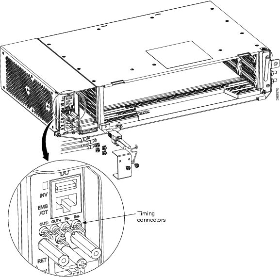
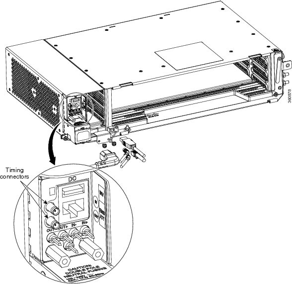
Complete either DLP-L54 Installing Timing Wires in Cisco NCS 2002 - ANSIor DLP-L55 Installing Timing Wires in Cisco NCS 2002- ETSI if you are provisioning external timing. |
|
Step 2 |
Complete DLP-L56 Installing LAN Wires in Cisco NCS 2002 to create an external LAN connection. You must connect a CAT-5 Ethernet cable to the LAN port on the TNC/TNCE/TSC/TSCE card to create an external LAN connection. Stop. You have completed this procedure. |
DLP-L54 Installing Timing Wires in Cisco NCS 2002 - ANSI
|
Purpose |
This task installs the timing wires in the DC-2 or AC-2 Power Module of NCS 2002 (ANSI). |
|
Tools/Equipment |
100-ohm wire wrap cable, wire wrap tool |
|
Prerequisite Procedures |
None |
|
Required/As Needed |
As needed |
|
Onsite/Remote |
Onsite |
|
Security Level |
None |
Procedure
|
Step 1 |
Locate the timing BITS connectors in the DC-2 or AC-2 Power Module, as shown in the figures below .   |
|
Step 2 |
Connect the wire wrap cable to the appropriate timing connector in the Power Module. |
|
Step 3 |
Connect the other end of the cable to the external source of the timing. Repeat this step for each cable that is needed. |
|
Step 4 |
Return to your originating procedure (NTP). |
DLP-L55 Installing Timing Wires in Cisco NCS 2002- ETSI
|
Purpose |
This task installs the timing wires in the AC-2 or DC-2E Power Module of NCS 2002 (ETSI). |
|
Tools/Equipment |
75-ohm coaxial cable with a DIN 1.0/2.3 miniature coax connector. The PID for the BITS IN/OUT cable is 15454-M-TMGCBL=. |
|
Prerequisite Procedures |
None |
|
Required/As Needed |
As needed |
|
Onsite/Remote |
Onsite |
|
Security Level |
None |
Procedure
|
Step 1 |
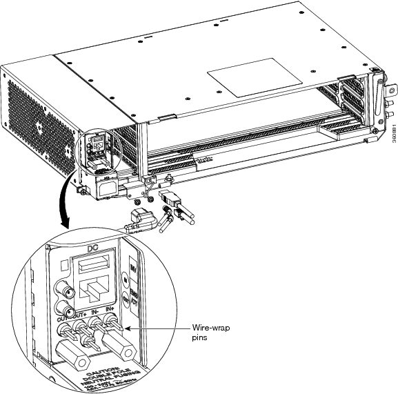
Locate the timing BITS connectors in the DC-2E or AC-2 Power Module, as shown in the figures below.   |
||
|
Step 2 |
Using a coaxial cable with DIN 1.0/2.3 miniature coax connectors, connect the clock cable to the appropriate connector in the Power Module. |
||
|
Step 3 |
Gently push the cable with the DIN 1.0/2.3 miniature coax connector down until the cable connector slides into the DIN 1.0/2.3 miniature coax connector on the Power Module with a click. The Power Module provides DIN 1.0/2.3 miniature coax connectors that are used for timing input and output. The input connectors for timing provide a 75-ohm termination. System cables that can convert timing clocks from 75 ohms to 100/120 ohms are available.
|
||
|
Step 4 |
Connect the other end of the cable to the external source of the timing. Repeat this step for each cable that is needed. |
||
|
Step 5 |
Return to your originating procedure (NTP). |
Installing Timing Wires in the Modular DC Power Module
|
Purpose |
This task installs the timing wires in the modular DC Power Module of NCS 2002. |
|
Tools/Equipment |
75-ohm coaxial cable with a DIN 1.0/2.3 miniature coaxial connector. The PID for the BITS IN/OUT cable is 15454-M-TMGCBL=. |
|
Prerequisite Procedures |
None |
|
Required/As Needed |
As needed |
|
Onsite/Remote |
Onsite |
|
Security Level |
None |
Procedure
|
Step 1 |
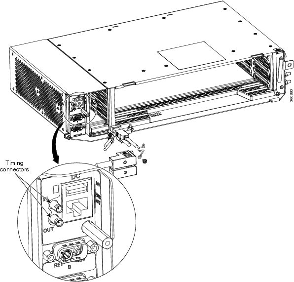
Locate the timing BITS connectors in the modular DC power module, as shown in the figure below. 
|
||||||||||||
|
Step 2 |
Using a coaxial cable with DIN 1.0/2.3 miniature coaxial connectors, connect the clock cable to the appropriate connector in the Power Module. |
||||||||||||
|
Step 3 |
Gently push the cable with the DIN 1.0/2.3 miniature coaxial connector down until the cable connector slides into the DIN 1.0/2.3 miniature coaxial connector on the Power Module with a click. The Power Module provides DIN 1.0/2.3 miniature coaxial connectors that are used for timing input and output. The input connectors for timing provide a 75-ohm termination. System cables that can convert timing clocks from 75 ohms to 100/120 ohms are available. See ITU-T G.813 for rules about provisioning timing references. |
||||||||||||
|
Step 4 |
Connect the other end of the cable to the external source of the timing. Repeat this step for each cable that is needed. |
||||||||||||
|
Step 5 |
Return to your originating procedure (NTP). |
DLP-L56 Installing LAN Wires in Cisco NCS 2002
|
Purpose |
This task installs the LAN wires in NCS 2002. |
|
Tools/Equipment |
Standard CAT-5 Ethernet cable straight-through for data terminal equipment (DTE) or crossover for data circuit-terminating equipment (DCE) or RJ-45 connector Crimping tool for RJ-45 connector 0.51 mm² or 0.64 mm² (#22 or #24 AWG) wire, preferably standard CAT-5 |
|
Prerequisite Procedures |
NTP-L35 Installing the Power and Ground to the NCS 2002 Shelf |
|
Required/As Needed |
As needed |
|
Onsite/Remote |
Onsite |
|
Security Level |
None |
Procedure
|
Step 1 |
Using a 0.51 mm² or 0.64 mm² (#22 or #24 AWG) wire or a standard CAT-5 Ethernet cable, connect the wires to the RJ-45 connector. |
|
Step 2 |
Return to your originating procedure (NTP). |
 Feedback