- Information About Starting ASAv Interface Configuration
Basic Interface Configuration (ASAv)
This chapter includes tasks for starting your interface configuration for the ASAv, including configuring Ethernet settings, redundant interfaces, and VLAN subinterfaces.
Information About Starting ASAv Interface Configuration
This section includes the following topics:
- ASAv Interfaces and Virtual NICs
- Interfaces in Transparent Mode
- Management Interface
- Redundant Interfaces
- Controlling Fragmentation with the Maximum Transmission Unit and TCP Maximum Segment Size
ASAv Interfaces and Virtual NICs
As a guest on a virtualized platform, the ASAv utilizes the network interfaces of the underlying physical platform. Each ASAv interface maps to a VMware virtual NIC (vNIC).
ASAv Interfaces
The ASAv includes the following Gigabit Ethernet interfaces:
Supported vNICs
VMware supports the following vNIC for ASAv interfaces:
- E1000—This vNIC is used by default.
- VMXNET3—To change to this emulator, you need to remove and re-add each vNIC. See Changing the vNIC Emulation for more information. You also need to disable Large Receive Offload (LRO) to avoid poor TCP performance. See the following VMware support articles:
http://kb.vmware.com/selfservice/microsites/search.do?cmd=displayKC&externalId=1027511
http://kb.vmware.com/selfservice/microsites/search.do?cmd=displayKC&externalId=2055140
ASAv Interface Concordance with vNICs
The vSphere Client Virtual Machine Properties screen (right-click the ASAv instance, and choose Edit Settings) shows each Network Adapter and the assigned network. However, that screen does not show the ASAv interface IDs (only Network Adapter IDs). See the following concordance of Network Adapter IDs and ASAv IDs:
|
|
|
|---|---|
Interfaces in Transparent Mode
Interfaces in transparent mode belong to a “bridge group,” one bridge group for each network. You can have up to 8 bridge groups of 4 interfaces. For more information about bridge groups, see Bridge Groups in Transparent Mode.
Management Interface
Management Interface Overview
You can manage the ASA by connecting to:
You may need to configure management access to the interface according to Chapter42, “Management Access”
Using Any Interface for Management-Only Traffic
You can use any interface as a dedicated management-only interface by configuring it for management traffic.
Management Interface for Transparent Mode
In transparent firewall mode, in addition to the maximum allowed through-traffic interfaces, you can also use the Management 0/0 interface (either the physical interface or a subinterface) as a separate management interface. You cannot use any other interface types as management interfaces. The management interface is not part of a normal bridge group. Note that for operational purposes, it is part of a non-configurable bridge group.

Note![]() In transparent firewall mode, the management interface updates the MAC address table in the same manner as a data interface; therefore you should not connect both a management and a data interface to the same switch unless you configure one of the switch ports as a routed port (by default Cisco Catalyst switches share a MAC address for all VLAN switch ports). Otherwise, if traffic arrives on the management interface from the physically-connected switch, then the ASA updates the MAC address table to use the management interface to access the switch, instead of the data interface. This action causes a temporary traffic interruption; the ASA will not re-update the MAC address table for packets from the switch to the data interface for at least 30 seconds for security reasons.
In transparent firewall mode, the management interface updates the MAC address table in the same manner as a data interface; therefore you should not connect both a management and a data interface to the same switch unless you configure one of the switch ports as a routed port (by default Cisco Catalyst switches share a MAC address for all VLAN switch ports). Otherwise, if traffic arrives on the management interface from the physically-connected switch, then the ASA updates the MAC address table to use the management interface to access the switch, instead of the data interface. This action causes a temporary traffic interruption; the ASA will not re-update the MAC address table for packets from the switch to the data interface for at least 30 seconds for security reasons.
No Through Traffic Support
The Management 0/0 interface is always set to management-only; you cannot use this interface for through traffic support.
Redundant Interfaces
A logical redundant interface consists of a pair of physical interfaces: an active and a standby interface. When the active interface fails, the standby interface becomes active and starts passing traffic. You can configure a redundant interface to increase the ASA reliability. This feature is separate from device-level failover, but you can configure redundant interfaces as well as device-level failover if desired.
Redundant Interface MAC Address
The redundant interface uses the MAC address of the first physical interface that you add. If you change the order of the member interfaces in the configuration, then the MAC address changes to match the MAC address of the interface that is now listed first. Alternatively, you can assign a MAC address to the redundant interface, which is used regardless of the member interface MAC addresses (see Configuring the MAC Address, MTU, and TCP MSS or the Configuring Multiple Contexts). When the active interface fails over to the standby, the same MAC address is maintained so that traffic is not disrupted.
Controlling Fragmentation with the Maximum Transmission Unit and TCP Maximum Segment Size
MTU Overview
The maximum transmission unit (MTU) specifies the maximum frame payload size that the ASA can transmit on a given Ethernet interface. The MTU value is the frame size without Ethernet headers, FCS, or VLAN tagging. The Ethernet header is 14 bytes and the FCS is 4 bytes. When you set the MTU to 1500, the expected frame size is 1518 bytes including the headers. If you are using VLAN tagging (which adds an additional 4 bytes), then when you set the MTU to 1500, the expected frame size is 1522. Do not set the MTU value higher to accommodate these headers. For information about accommodating TCP headers for encapsulation, do not alter the MTU setting; instead change the TCP Maximum Segment Size (the TCP Maximum Segment Size Overview).
Note![]() The ASA can receive frames larger than the configured MTU as long as there is room in memory. See Enabling Jumbo Frame Support to increase memory for larger frames.
The ASA can receive frames larger than the configured MTU as long as there is room in memory. See Enabling Jumbo Frame Support to increase memory for larger frames.
Default MTU
The default MTU on the ASA is 1500 bytes. This value does not include the 18 or more bytes for the Ethernet header, CRC, VLAN tagging, and so on.
Path MTU Discovery
The ASA supports Path MTU Discovery (as defined in RFC 1191), which lets all devices in a network path between two hosts coordinate the MTU so that they can standardize on the lowest MTU in the path.
Setting the MTU and Jumbo Frames
See Configuring the MAC Address, MTU, and TCP MSS.
See Enabling Jumbo Frame Support.
- Matching MTUs on the traffic path—We recommend that you set the MTU on all ASA interfaces and other device interfaces along the traffic path to be the same. Matching MTUs prevents intermediate devices from fragmenting the packets.
- Accommodating jumbo frames—If you enable jumbo frames, you can set the MTU up to 9000 bytes.
TCP Maximum Segment Size Overview
The TCP maximum segment size (TCP MSS) is the size of the TCP payload before any TCP headers are added. UDP packets are not affected. The client and the server exchange TCP MSS values during the three-way handshake when establishing the connection.
You can set the TCP MSS on the ASA. If either endpoint of a connection requests a TCP MSS that is larger than the value set on the ASA, the ASA overwrites the TCP MSS in the request packet with the ASA maximum. If the host or server does not request a TCP MSS, then the ASA assumes the RFC 793-default value of 536 bytes, but does not modify the packet. You can also configure the minimum TCP MSS; if a host or server requests a very small TCP MSS, the ASA can adjust the value up. By default, the minimum TCP MSS is not enabled.
For example, you configure the default MTU of 1500 bytes. A host requests an MSS of 1700. If the ASA maximum TCP MSS is 1380, then the ASA changes the MSS value in the TCP request packet to 1380. The server then sends 1380-byte packets.
Default TCP MSS
By default, the maximum TCP MSS on the ASA is 1380 bytes. This default accommodates VPN connections where the headers can add up to 120 bytes; this value fits within the default MTU of 1500 bytes.
Setting the TCP MSS for VPN and Non-VPN Traffic
See Configuring the MAC Address, MTU, and TCP MSS.
- Non-VPN traffic—If you do not use VPN and do not need extra space for headers, then you should disable the TCP MSS limit and accept the value established between connection endpoints. Because connection endpoints typically derive the TCP MSS from the MTU, non-VPN packets usually fit this TCP MSS.
- VPN traffic—Set the maximum TCP MSS to the MTU - 120. For example, if you use jumbo frames and set the MTU to a higher value, then you need to set the TCP MSS to accommodate the new MTU.
Licensing Requirements for ASAv Interfaces
|
|
|
|---|---|
VLANs1: Standard and Premium License: 50 Interfaces of all types2: |
|
VLANs 1 : Standard and Premium License: 200 Interfaces of all types 2 : |
Guidelines and Limitations
This section includes the guidelines and limitations for this feature.
- For transparent mode, you can configure up to 8 bridge groups.
- Each bridge group can include up to 4 interfaces.
- When you use a redundant interface as a failover link, it must be pre-configured on both units in the failover pair; you cannot configure it on the primary unit and expect it to replicate to the secondary unit because the failover link itself is required for replication.
- If you use a redundant interface for the state link, no special configuration is required; the configuration can replicate from the primary unit as normal.
- You can monitor redundant interfaces for failover. When an active member interface fails over to a standby interface, this activity does not cause the redundant interface to appear to be failed when being monitored for device-level failover. Only when all physical interfaces fail does the redundant interface appear to be failed.
- You cannot share a failover or state interface with a data interface.
Redundant Interface Guidelines
- You can configure up to 8 redundant interface pairs.
- All ASA configuration refers to the logical redundant interface instead of the member physical interfaces.
- If you shut down the active interface, then the standby interface becomes active.
- You cannot set a redundant interface as management-only.
- For failover guidelines, see Failover Guidelines.
Default Settings
This section lists default settings for interfaces if you do not have a factory default configuration. For information about the factory default configurations, see Factory Default Configurations.
- Physical interfaces—Disabled.
- Redundant Interfaces—Enabled. However, for traffic to pass through the redundant interface, the member physical interfaces must also be enabled.
- Subinterfaces—Enabled. However, for traffic to pass through the subinterface, the physical interface must also be enabled.
By default, the physical interface uses the burned-in MAC address, and all subinterfaces of a physical interface use the same burned-in MAC address.
Starting Interface Configuration (ASAv)
This section includes the following topics:
- Task Flow for Starting Interface Configuration
- Changing the vNIC Emulation
- Enabling the Physical Interface and Configuring Ethernet Parameters
- Configuring a Redundant Interface
- Configuring VLAN Subinterfaces and 802.1Q Trunking
- Enabling Jumbo Frame Support
Task Flow for Starting Interface Configuration
To start configuring interfaces, perform the following steps:
Step 1![]() (Optional) Change the vNIC emulation. See Changing the vNIC Emulation.
(Optional) Change the vNIC emulation. See Changing the vNIC Emulation.
Step 2![]() Enable the physical interface, and optionally change Ethernet parameters. See Enabling the Physical Interface and Configuring Ethernet Parameters.
Enable the physical interface, and optionally change Ethernet parameters. See Enabling the Physical Interface and Configuring Ethernet Parameters.
Physical interfaces are disabled by default.
Step 3![]() (Optional) Configure redundant interface pairs. See Configuring a Redundant Interface.
(Optional) Configure redundant interface pairs. See Configuring a Redundant Interface.
A logical redundant interface pairs an active and a standby physical interface. When the active interface fails, the standby interface becomes active and starts passing traffic.
Step 4![]() (Optional) Configure VLAN subinterfaces. See Configuring VLAN Subinterfaces and 802.1Q Trunking.
(Optional) Configure VLAN subinterfaces. See Configuring VLAN Subinterfaces and 802.1Q Trunking.
Step 5![]() (Optional) Enable jumbo frame support according to the Enabling Jumbo Frame Support.
(Optional) Enable jumbo frame support according to the Enabling Jumbo Frame Support.
Changing the vNIC Emulation
By default, all ASAv interfaces use vNICs with E1000 emulation in VMware. To change to VMXNET3, you need to remove the old vNICs and add new ones with the new emulation type.
Prerequisites
Detailed Steps
Step 1![]() In the VMware vSphere Web Client, select the ASAv instance.
In the VMware vSphere Web Client, select the ASAv instance.
Step 2![]() If the ASAv is powered on, you must power it off. In the right pane, click Power Off the virtual machine. Confirm by clicking Yes.
If the ASAv is powered on, you must power it off. In the right pane, click Power Off the virtual machine. Confirm by clicking Yes.
Step 3![]() Click Edit virtual machine settings.
Click Edit virtual machine settings.
Step 4![]() For the vNIC (called a Network adapter in the vSphere Web Client) that you want to change, click the X to the right of the entry. See ASAv Interface Concordance with vNICs for information about which ASAv interface matches each network adapter.
For the vNIC (called a Network adapter in the vSphere Web Client) that you want to change, click the X to the right of the entry. See ASAv Interface Concordance with vNICs for information about which ASAv interface matches each network adapter.

Step 5![]() Repeat for any additional network adapters, and click OK to accept your changes.
Repeat for any additional network adapters, and click OK to accept your changes.
Step 6![]() Open the Edit Settings dialog box again.
Open the Edit Settings dialog box again.
Step 7![]() From the New device drop-down list, choose Network, and then click Add to re-add each network adapter using the new emulator. vSphere adds new network adapters in numerical order. For example, if you remove network adapter 6, 1, and 10 in any order, then when you add new network adapters, they are added in this order: 1, 6, 10.
From the New device drop-down list, choose Network, and then click Add to re-add each network adapter using the new emulator. vSphere adds new network adapters in numerical order. For example, if you remove network adapter 6, 1, and 10 in any order, then when you add new network adapters, they are added in this order: 1, 6, 10.

Step 8![]() Click the expand arrow next to New Network.
Click the expand arrow next to New Network.

Step 9![]() For the New Network, choose the appropriate network.
For the New Network, choose the appropriate network.
Step 10![]() For the Adapter Type, choose the new type.
For the Adapter Type, choose the new type.
Step 11![]() Repeat Step 7 through 10 to add more vNICs.
Repeat Step 7 through 10 to add more vNICs.
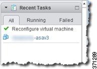
vSphere takes a moment to reconfigure the ASAv with the new vNICs (see the Recent Tasks for status).
Step 13![]() Restart the ASAv by clicking Power On the virtual machine.
Restart the ASAv by clicking Power On the virtual machine.
Enabling the Physical Interface and Configuring Ethernet Parameters
Detailed Steps
Step 1![]() Choose the Configuration > Device Setup > Interfaces pane.
Choose the Configuration > Device Setup > Interfaces pane.
By default, all physical interfaces are listed.
Step 2![]() Click a physical interface that you want to configure, and click Edit.
Click a physical interface that you want to configure, and click Edit.
The Edit Interface dialog box appears.
Note![]() This procedure only covers a subset of the parameters on the Edit Interface dialog box; to configure other parameters, see “Routed Mode Interfaces,” or Chapter16, “Transparent Mode Interfaces”
This procedure only covers a subset of the parameters on the Edit Interface dialog box; to configure other parameters, see “Routed Mode Interfaces,” or Chapter16, “Transparent Mode Interfaces”
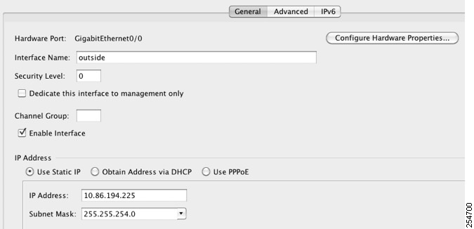
Step 3![]() To enable the interface, check the Enable Interface check box.
To enable the interface, check the Enable Interface check box.
Step 4![]() To add a description, enter text in the Description field.
To add a description, enter text in the Description field.
The description can be up to 240 characters on a single line, without carriage returns. In the case of a failover or state link, the description is fixed as “LAN Failover Interface,” “STATE Failover Interface,” or “LAN/STATE Failover Interface,” for example. You cannot edit this description. The fixed description overwrites any description you enter here if you make this interface a failover or state link.
Step 5![]() (Optional) To set the media type, duplex, speed, and enable pause frames for flow control, click Configure Hardware Properties.
(Optional) To set the media type, duplex, speed, and enable pause frames for flow control, click Configure Hardware Properties.
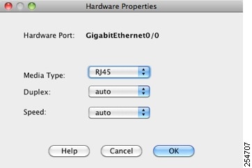
Note![]() The Media Type is always RJ-45.
The Media Type is always RJ-45.
a.![]() To set the duplex for RJ-45 interfaces, choose Full, Half, or Auto, depending on the interface type, from the Duplex drop-down list.
To set the duplex for RJ-45 interfaces, choose Full, Half, or Auto, depending on the interface type, from the Duplex drop-down list.
b.![]() To set the speed, choose a value from the Speed drop-down list.
To set the speed, choose a value from the Speed drop-down list.
c.![]() Click OK to accept the Hardware Properties changes.
Click OK to accept the Hardware Properties changes.
d.![]() To enable pause (XOFF) frames for flow control, check the Enable Pause Frame check box.
To enable pause (XOFF) frames for flow control, check the Enable Pause Frame check box.
If you have a traffic burst, dropped packets can occur if the burst exceeds the buffering capacity of the FIFO buffer on the NIC and the receive ring buffers. Enabling pause frames for flow control can alleviate this issue. Pause (XOFF) and XON frames are generated automatically by the NIC hardware based on the FIFO buffer usage. A pause frame is sent when the buffer usage exceeds the high-water mark. The default high_water value is 24 KB; you can set it between 0 and 47 KB. After a pause is sent, an XON frame can be sent when the buffer usage is reduced below the low-water mark. By default, the low_water value is 16 KB; you can set it between 0 and 47 KB. The link partner can resume traffic after receiving an XON, or after the XOFF expires, as controlled by the timer value in the pause frame. The default pause_time value is 26624; you can set it between 0 and 65535. If the buffer usage is consistently above the high-water mark, pause frames are sent repeatedly, controlled by the pause refresh threshold value.
To change the default values for the Low Watermark, High Watermark, and Pause Time, uncheck the Use Default Values check box.
Note![]() Only flow control frames defined in 802.3x are supported. Priority-based flow control is not supported.
Only flow control frames defined in 802.3x are supported. Priority-based flow control is not supported.
Step 6![]() Click OK to accept the Interface changes.
Click OK to accept the Interface changes.
What to Do Next
- Configure redundant interface pairs. See Configuring a Redundant Interface.
- Configure VLAN subinterfaces. See Configuring VLAN Subinterfaces and 802.1Q Trunking.
- Configure jumbo frame support. See Enabling Jumbo Frame Support.
- Complete the interface configuration. See “Routed Mode Interfaces,” or Chapter16, “Transparent Mode Interfaces”
Configuring a Redundant Interface
A logical redundant interface consists of a pair of physical interfaces: an active and a standby interface. When the active interface fails, the standby interface becomes active and starts passing traffic. You can configure a redundant interface to increase the ASA reliability. This feature is separate from device-level failover, but you can configure redundant interfaces as well as failover if desired.
This section describes how to configure redundant interfaces and includes the following topics:
Configuring a Redundant Interface
This section describes how to create a redundant interface. By default, redundant interfaces are enabled.
Guidelines and Limitations
- You can configure up to 8 redundant interface pairs.
- Redundant interface delay values are configurable, but by default the ASA inherits the default delay values based on the physical type of its member interfaces.
- See also the Redundant Interface Guidelines.
Prerequisites
- Both member interfaces must be of the same physical type. For example, both must be GigabitEthernet.
- You cannot add a physical interface to the redundant interface if you configured a name for it. You must first remove the name in the Configuration > Device Setup > Interfaces pane.

Detailed Steps
Step 1![]() Choose the Configuration > Device Setup > Interfaces pane.
Choose the Configuration > Device Setup > Interfaces pane.
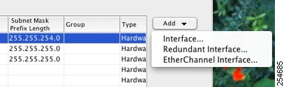
Step 2![]() Choose Add > Redundant Interface.
Choose Add > Redundant Interface.
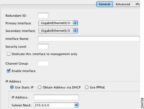
The Add Redundant Interface dialog box appears.
Note![]() This procedure only covers a subset of the parameters on the Edit Redundant Interface dialog box; to configure other parameters, see “Routed Mode Interfaces,” or Chapter16, “Transparent Mode Interfaces”
This procedure only covers a subset of the parameters on the Edit Redundant Interface dialog box; to configure other parameters, see “Routed Mode Interfaces,” or Chapter16, “Transparent Mode Interfaces”
Step 3![]() In the Redundant ID field, enter an integer between 1 and 8.
In the Redundant ID field, enter an integer between 1 and 8.
Step 4![]() From the Primary Interface drop-down list, choose the physical interface you want to be primary.
From the Primary Interface drop-down list, choose the physical interface you want to be primary.
Be sure to pick an interface that does not have a subinterface and that has not already been allocated to a context.
Step 5![]() From the Secondary Interface drop-down list, choose the physical interface that you want to be secondary.
From the Secondary Interface drop-down list, choose the physical interface that you want to be secondary.
Step 6![]() If the interface is not already enabled, check the Enable Interface check box.
If the interface is not already enabled, check the Enable Interface check box.
The interface is enabled by default. To disable it, uncheck the check box.
Step 7![]() To add a description, enter text in the Description field.
To add a description, enter text in the Description field.
The description can be up to 240 characters on a single line, without carriage returns. In the case of a failover or state link, the description is fixed as “LAN Failover Interface,” “STATE Failover Interface,” or “LAN/STATE Failover Interface,” for example. You cannot edit this description. The fixed description overwrites any description you enter here if you make this interface a failover or state link.
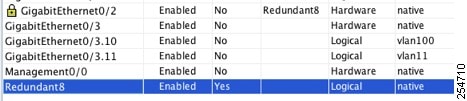
You return to the Interfaces pane. The member interfaces now show a lock to the left of the interface ID showing that only basic parameters can be configured for it. The redundant interface is added to the table.
What to Do Next
- Configure VLAN subinterfaces. See Configuring VLAN Subinterfaces and 802.1Q Trunking.
- Configure jumbo frame support. See Enabling Jumbo Frame Support.
- Complete the interface configuration. See “Routed Mode Interfaces,” or Chapter16, “Transparent Mode Interfaces”
Changing the Active Interface
By default, the active interface is the first interface listed in the configuration, if it is available. To view which interface is active, enter the following command in the Tools > Command Line Interface tool:
To change the active interface, enter the following command:
where the redundant number argument is the redundant interface ID, such as redundant1.
The physical_interface is the member interface ID that you want to be active.
Configuring VLAN Subinterfaces and 802.1Q Trunking
Subinterfaces let you divide a physical or redundant interface into multiple logical interfaces that are tagged with different VLAN IDs. An interface with one or more VLAN subinterfaces is automatically configured as an 802.1Q trunk. Because VLANs allow you to keep traffic separate on a given physical interface, you can increase the number of interfaces available to your network without adding additional physical interfaces or ASAs.
Guidelines and Limitations
- Maximum subinterfaces—To determine how many VLAN subinterfaces are allowed for your model, see Licensing Requirements for ASAv Interfaces.
- Preventing untagged packets on the physical interface—If you use subinterfaces, you typically do not also want the physical interface to pass traffic, because the physical interface passes untagged packets. This property is also true for the active physical interface in a redundant interface pair. Because the physical or redundant interface must be enabled for the subinterface to pass traffic, ensure that the physical or redundant interface does not pass traffic by not configuring a name for the interface. If you want to let the physical or redundant interface pass untagged packets, you can configure the name as usual. See “Routed Mode Interfaces,” or “Transparent Mode Interfaces,” for more information about completing the interface configuration.
Detailed Steps
Step 1![]() Choose the Configuration > Device Setup > Interfaces pane.
Choose the Configuration > Device Setup > Interfaces pane.
Step 2![]() Choose Add > Interface.
Choose Add > Interface.
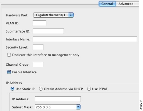
The Add Interface dialog box appears.
Note![]() This procedure only covers a subset of the parameters on the Edit Interface dialog box; to configure other parameters, see “Routed Mode Interfaces,” or Chapter16, “Transparent Mode Interfaces”
This procedure only covers a subset of the parameters on the Edit Interface dialog box; to configure other parameters, see “Routed Mode Interfaces,” or Chapter16, “Transparent Mode Interfaces”
Step 3![]() From the Hardware Port drop-down list, choose the physical or redundant interface to which you want to add the subinterface.
From the Hardware Port drop-down list, choose the physical or redundant interface to which you want to add the subinterface.
Step 4![]() If the interface is not already enabled, check the Enable Interface check box.
If the interface is not already enabled, check the Enable Interface check box.
The interface is enabled by default. To disable it, uncheck the check box.
Step 5![]() In the VLAN ID field, enter the VLAN ID between 1 and 4095.
In the VLAN ID field, enter the VLAN ID between 1 and 4095.
Some VLAN IDs might be reserved on connected switches, so check the switch documentation for more information.
Step 6![]() In the Subinterface ID field, enter the subinterface ID as an integer between 1 and 4294967293.
In the Subinterface ID field, enter the subinterface ID as an integer between 1 and 4294967293.
The number of subinterfaces allowed depends on your platform. You cannot change the ID after you set it.
Step 7![]() (Optional) In the Description field, enter a description for this interface.
(Optional) In the Description field, enter a description for this interface.
The description can be up to 240 characters on a single line, without carriage returns. In the case of a failover or state link, the description is fixed as “LAN Failover Interface,” “STATE Failover Interface,” or “LAN/STATE Failover Interface,” for example. You cannot edit this description. The fixed description overwrites any description you enter here if you make this interface a failover or state link.
You return to the Interfaces pane.
What to Do Next
- Configure jumbo frame support. See Enabling Jumbo Frame Support.
- Complete the interface configuration. See “Routed Mode Interfaces,” or Chapter16, “Transparent Mode Interfaces”
Enabling Jumbo Frame Support
A jumbo frame is an Ethernet packet larger than the standard maximum of 1518 bytes (including Layer 2 header and FCS), up to 9216 bytes. You can enable support for jumbo frames for all interfaces by increasing the amount of memory to process Ethernet frames. Assigning more memory for jumbo frames might limit the maximum use of other features, such as ACLs. See Controlling Fragmentation with the Maximum Transmission Unit and TCP Maximum Segment Size for more information.
Prerequisites
- Changes in this setting require you to reload the ASA.
- Be sure to set the MTU for each interface that needs to transmit jumbo frames to a higher value than the default 1500; for example, set the value to 9000. See Configuring the MAC Address, MTU, and TCP MSS.
- Be sure to adjust the TCP MSS, either to disable it for non-VPN traffic, or to increase it in accord with the MTU according to the Configuring the MAC Address, MTU, and TCP MSS.
Detailed Steps
Setting the MTU larger than 1500 bytes automatically enables jumbo frames. To manually enable or disable this setting, choose Configuration > Device Setup > Interfaces, and click the Enable jumbo frame support check box.
What to Do Next
Complete the interface configuration. See “Routed Mode Interfaces,” or Chapter16, “Transparent Mode Interfaces”
Monitoring Interfaces
This section includes the following topics:
ARP Table
The Monitoring > Interfaces > ARP Table pane displays the ARP table, including static and dynamic entries. The ARP table includes entries that map a MAC address to an IP address for a given interface.
- Interface —Lists the interface name associated with the mapping.
- IP Address —Shows the IP address.
- MAC Address —Shows the MAC address.
- Proxy ARP—Displays Yes if proxy ARP is enabled on the interface. Displays No if proxy ARP is not enabled on the interface.
- Clear —Clears the dynamic ARP table entries. Static entries are not cleared.
- Refresh —Refreshes the table with current information from the ASA and updates Last Updated date and time.
- Last Updated — Display only . Shows the date and time the display was updated.
MAC Address Table
The Monitoring > Interfaces > MAC Address Table pane shows the static and dynamic MAC address entries. See MAC Address Table for more information about the MAC address table and adding static entries.
- Interface—Shows the interface name associated with the entry.
- MAC Address—Shows the MAC address.
- Type—Shows if the entry is static or dynamic.
- Age—Shows the age of the entry, in minutes. To set the timeout, see MAC Address Table.
- Refresh—Refreshes the table with current information from the ASA.
Interface Graphs
The Monitoring > Interfaces > Interface Graphs pane lets you view interface statistics in graph or table form. The number of statistics shown for a subinterface is a subset of the number of statistics shown for a physical interface.
- Available Graphs for—Lists the types of statistics available for monitoring. You can choose up to four types of statistics to show in one graph pane. You can open multiple graph panes at the same time.
–![]() Byte Counts—Shows the number of bytes input and output on the interface.
Byte Counts—Shows the number of bytes input and output on the interface.
–![]() Packet Counts—Shows the number of packets input and output on the interface.
Packet Counts—Shows the number of packets input and output on the interface.
–![]() Packet Rates—Shows the rate of packets input and output on the interface.
Packet Rates—Shows the rate of packets input and output on the interface.
–![]() Bit Rates—Shows the bit rate for the input and output of the interface.
Bit Rates—Shows the bit rate for the input and output of the interface.
–![]() Drop Packet Count—Shows the number of packets dropped on the interface.
Drop Packet Count—Shows the number of packets dropped on the interface.
These additional statistics display for physical interfaces:
–![]() Buffer Resources—Shows the following statistics:
Buffer Resources—Shows the following statistics:
Overruns—The number of times that the ASA was incapable of handing received data to a hardware buffer because the input rate exceeded the ASA capability to handle the data.
Underruns—The number of times that the transmitter ran faster than the ASA could handle.
No Buffer—The number of received packets discarded because there was no buffer space in the main system. Compare this with the ignored count. Broadcast storms on Ethernet networks are often responsible for no input buffer events.
–![]() Packet Errors—Shows the following statistics:
Packet Errors—Shows the following statistics:
CRC—The number of Cyclical Redundancy Check errors. When a station sends a frame, it appends a CRC to the end of the frame. This CRC is generated from an algorithm based on the data in the frame. If the frame is altered between the source and destination, the ASA notes that the CRC does not match. A high number of CRCs is usually the result of collisions or a station transmitting bad data.
Frame—The number of frame errors. Bad frames include packets with an incorrect length or bad frame checksums. This error is usually the result of collisions or a malfunctioning Ethernet device.
Input Errors—The number of total input errors, including the other types listed here. Other input-related errors can also cause the input error count to increase, and some datagrams might have more than one error; therefore, this sum might exceed the number of errors listed for the other types.
Runts—The number of packets that are discarded because they are smaller than the minimum packet size, which is 64 bytes. Runts are usually caused by collisions. They might also be caused by poor wiring and electrical interference.
Giants—The number of packets that are discarded because they exceed the maximum packet size. For example, any Ethernet packet that is greater than 1518 bytes is considered a giant.
Deferred—For FastEthernet interfaces only. The number of frames that were deferred before transmission due to activity on the link.
–![]() Miscellaneous—Shows statistics for received broadcasts.
Miscellaneous—Shows statistics for received broadcasts.
–![]() Collision Counts—For FastEthernet interfaces only. Shows the following statistics:
Collision Counts—For FastEthernet interfaces only. Shows the following statistics:
Output Errors—The number of frames not transmitted because the configured maximum number of collisions was exceeded. This counter should only increment during heavy network traffic.
Collisions—The number of messages retransmitted due to an Ethernet collision (single and multiple collisions). This usually occurs on an overextended LAN (Ethernet or transceiver cable too long, more than two repeaters between stations, or too many cascaded multiport transceivers). A packet that collides is counted only once by the output packets.
Late Collisions—The number of frames that were not transmitted because a collision occurred outside the normal collision window. A late collision is a collision that is detected late in the transmission of the packet. Normally, these should never happen. When two Ethernet hosts try to talk at once, they should collide early in the packet and both back off, or the second host should see that the first one is talking and wait. If you get a late collision, a device is jumping in and trying to send the packet on the Ethernet while the ASA is partly finished sending the packet. The ASA does not resend the packet, because it may have freed the buffers that held the first part of the packet. This is not a real problem because networking protocols are designed to cope with collisions by resending packets. However, late collisions indicate that a problem exists in your network. Common problems are large repeated networks and Ethernet networks running beyond the specification.
–![]() Input Queue—Shows the number of packets in the input queue, the current and the maximum, including the following statistics:
Input Queue—Shows the number of packets in the input queue, the current and the maximum, including the following statistics:
Hardware Input Queue—The number of packets in the hardware queue.
Software Input Queue—The number of packets in the software queue.
–![]() Output Queue—Shows the number of packets in the output queue, the current and the maximum, including the following statistics:
Output Queue—Shows the number of packets in the output queue, the current and the maximum, including the following statistics:
Hardware Output Queue—The number of packets in the hardware queue.
Software Output Queue—The number of packets in the software queue.
- Add—Adds the selected statistic type to the selected graph pane.
- Remove—Removes the selected statistic type from the selected graph pane. This button name changes to Delete if the item you are removing was added from another pane, and is not being returned to the Available Graphs pane.
- Show Graphs—Shows the graph pane name to which you want to add a statistic type. If you have a graph pane already open, a new graph pane is listed by default. If you want to add a statistic type to an already open graph, choose the open graph pane name. The statistics already included on the graph are shown in the Selected Graphs pane, to which you can add additional types. Graph panes are named for ASDM followed by the interface IP address and the name “Graph”. Subsequent graphs are named “Graph (2)”, and so on.
- Selected Graphs—Shows the statistic types that you want to show in the selected graph pane. You can include up to four types.
–![]() Show Graphs—Shows the graph pane or updates the graph with additional statistic types if added.
Show Graphs—Shows the graph pane or updates the graph with additional statistic types if added.
Graph/Table
The Monitoring > Interfaces > Interface Graphs > Graph/Table pane shows a graph for the selected statistics. The Graph pane can show up to four graphs and tables at a time. By default, the graph or table displays the real-time statistics. If you enable History Metrics (see Enabling History Metrics), you can view statistics for past time periods.
- View—Sets the time period for the graph or table. To view any time period other than real-time, enable History Metrics (see Enabling History Metrics). The data is updated according to the specification of the following options:
–![]() Real-time, data every 10 sec
Real-time, data every 10 sec
–![]() Last 10 minutes, data every 10 sec
Last 10 minutes, data every 10 sec
–![]() Last 60 minutes, data every 1 min
Last 60 minutes, data every 1 min
–![]() Last 12 hours, data every 12 min
Last 12 hours, data every 12 min
–![]() Last 5 days, data every 2 hours
Last 5 days, data every 2 hours
- Export—Exports the graph in comma-separated value format. If there is more than one graph or table in the Graph pane, the Export Graph Data dialog box appears. Choose one or more of the graphs and tables listed by checking the check box next to the name.
- Print—Prints the graph or table. If there is more than one graph or table in the Graph pane, the Print Graph dialog box appears. Choose the graph or table that you want to print from the Graph/Table Name list.
- Bookmark—Opens a browser pane with a single link for all graphs and tables in the Graphs pane, as well as individual links for each graph or table. You can then copy these URLs as bookmarks in your browser. ASDM does not have to be running when you open the URL for a graph; the browser launches ASDM and then displays the graph.
Where to Go Next
Complete the interface configuration according to “Routed Mode Interfaces,” or Chapter16, “Transparent Mode Interfaces”
Feature History for ASAv Interfaces
Table 14-1 lists the release history for this feature.
|
|
|
|
|---|---|---|
 Feedback