Management Interface
In Version 7.3 and earlier, the physical management interface is shared between the Diagnostic logical interface and the Management logical interface. In Version 7.4 and later, the Diagnostic interface is merged with Management for a simplified user experience.
Management Interface
The Management interface is separate from the other interfaces on the device. It is used to set up and register the device to the Cloud-Delivered Firewall Management Center. It uses its own IP address and static routing. You can configure its settings at the CLI using the configure network command. You can also view its status on the page. If you change the IP address at the CLI after you add it to the Cloud-Delivered Firewall Management Center, you can match the IP address in the Cloud-Delivered Firewall Management Center in the area.
You can alternatively manage the Firewall Threat Defense using a data interface instead of the Management interface.
Diagnostic Interface
For new devices using 7.4 and later, you cannot use the legacy Diagnostic interface. Only the merged Management interface is available.
If you upgraded to 7.4 or later, and you did not have any configuration for the Diagnostic interface, then the interfaces will merge automatically.
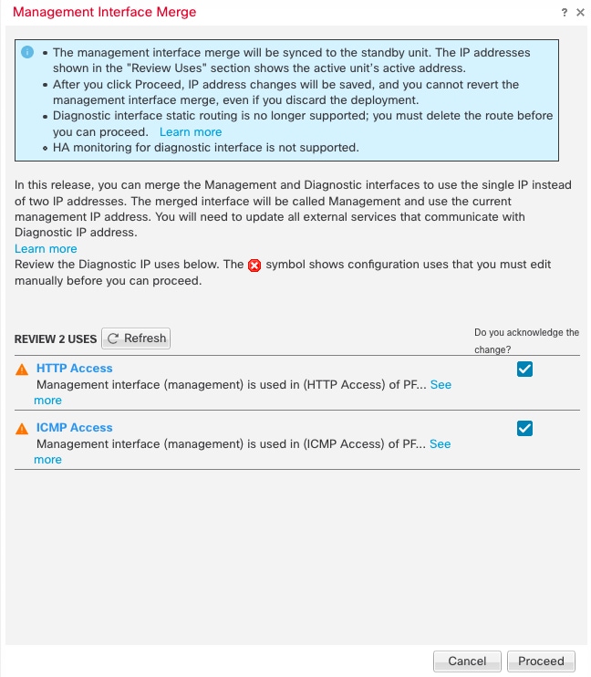
If you upgraded to 7.4 or later, and you have configuration for the Diagnostic interface, then you have the choice to merge the interfaces manually, or you can continue to use the separate Diagnostic interface. Note that support for the Diagnostic interface will be removed in a later release, so you should plan to merge the interfaces as soon as possible. To manually merge the Management and Diagnostic interfaces, see Merge the Management and Diagnostic Interfaces. Configurations that prevent an automatic merge include the following:
-
A data interface named "management"—This name is reserved for use with the merged Management interface.
-
IP Address on Diagnostic
-
DNS enabled on Diagnostic
-
Syslog, SNMP, RADIUS or AD (for remote access VPN) source interface is Diagnostic
-
RADIUS or AD (for remote access VPN) with no source interface specified, and there is at least one interface configured as management-only (including Diagnostic)—The default route lookup for these services has changed from the management-only routing table to the data routing table, with no fallback to management. Therefore, you cannot use a management-only interface other than Management.
-
Static routes on Diagnostic
-
Dynamic routing on Diagnostic
-
HTTP server on Diagnostic
-
ICMP on Diagnostic
-
DDNS for Diagnostic
-
FlexConfig using Diagnostic
For more information about how the legacy Diagnostic interface operates, see the 7.3 version of this guide.


 )
)


 )
)


 ).
).


 Feedback