Site-to-Site VPNs

About Site-to-Site VPN

Secure Firewall Threat Defense site-to-site VPN supports the following features:

  • Both IPsec IKEv1 & IKEv2 protocols.

  • Certificates and automatic or manual preshared keys for authentication.

  • IPv4 & IPv6. All combinations of inside and outside are supported.

  • IPsec IKEv2 Site-to-Site VPN topologies provide configuration settings to comply with security certifications.

  • Static and dynamic Interfaces.

  • HA environments for both management center and threat defense.

  • VPN alerts when the tunnel goes down.

  • Tunnel statistics available using the threat defense Unified CLI.

  • IKEv1 and IKEv2 back-up peer configuration for point-to-point extranet and hub-and-spoke VPNs.

  • Extranet device as hub in 'Hub and Spokes' deployments.

  • Dynamic IP address for a managed endpoint pairing with extranet device in 'Point to Point' deployments.

  • Dynamic IP address for extranet device as an endpoint.

  • Hub as extranet in 'Hub and Spokes' deployments.

VPN Topology

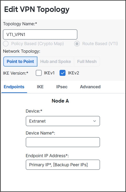
To create a new site-to-site VPN topology you must, specify a unique name, a topology type, choose the IKE version that is used for IPsec IKEv1 or IKEv2, or both. Also, determine your authentication method. Once configured, you deploy the topology to threat defense devices. The Secure Firewall Management Center configures site-to-site VPNs on threat defense devices only.

You can select from three types of topologies, containing one or more VPN tunnels:

  • Point-to-point (PTP) deployments establish a VPN tunnel between two endpoints.

  • Hub and Spoke deployments establish a group of VPN tunnels connecting a hub endpoint to a group of spoke nodes.

  • Full Mesh deployments establish a group of VPN tunnels among a set of endpoints.

IPsec and IKE

In the Secure Firewall Management Center, site-to-site VPNs are configured based on IKE policies and IPsec proposals that are assigned to VPN topologies. Policies and proposals are sets of parameters that define the characteristics of a site-to-site VPN, such as the security protocols and algorithms that are used to secure traffic in an IPsec tunnel. Several policy types may be required to define a full configuration image that can be assigned to a VPN topology.

Authentication

For authentication of VPN connections, configure a preshared key in the topology, or a trustpoint on each device. Preshared keys allow for a secret key, used during the IKE authentication phase, to be shared between two peers. A trustpoint includes the identity of the CA, CA-specific parameters, and an association with a single enrolled identity certificate.

Extranet Devices

Each topology type can include extranet devices, devices that you don’t manage in management center. These include:

  • Cisco devices that Secure Firewall Management Center supports, but for which your organization isn’t responsible. Such as spokes in networks managed by other organizations within your company, or a connection to a service provider or partner's network.

  • Non-Cisco devices. You can’t use Secure Firewall Management Center to create and deploy configurations to non-Cisco devices.

Add non-Cisco devices, or Cisco devices not managed by the Secure Firewall Management Center, to a VPN topology as "Extranet" devices. Also specify the IP address of each remote device.

Secure Firewall Threat Defense Site-to-site VPN Guidelines and Limitations

  • Site-to-site VPN supports ECMP zone interfaces.

  • You must configure all nodes in a topology with either crypto ACL or a protected network. You cannot configure a topology with crypto ACL on one node and protected network on another.

  • You can configure a VPN connection across domains by using an extranet peer for the endpoint not in the current domain.

  • You can backup Threat Defense VPNs using the management center backup.

  • IKEv1 does not support CC/UCAPL-compliant devices. We recommend that you use IKEv2 for these devices.

  • You cannot move a VPN topology between domains.

  • VPN does not support network objects with a 'range' option.

  • Threat Defense VPNs do not currently support PDF export and policy comparison.

  • There is no per-tunnel or per-device edit option for threat defense VPNs, you can edit only the whole topology.

  • The management center does not verify the device interface address verification for transport mode when you select a crypto ACL.

  • There is no support for automatic mirror ACE generation. Mirror ACE generation for the peer is a manual process on either side.

  • With crypto ACL, the management center supports only point to point VPN and does not support tunnel health events.

  • Whenever IKE ports 500/4500 are in use or when there are some active PAT translations, you cannot configure a site-to-site VPN on the same ports as it fails to start the service on those ports.

  • Tunnel status is not updated in realtime, but at an interval of five minutes in the management center.

  • You cannot use the character " (double quote) as part of pre-shared keys. If you have used " in a pre-shared key, ensure that you change the character.

  • In a site-to-site VPN configuration with two devices managed by the same management center, you cannot configure the devices as backup peers. You must configure one of peer devices in the topology as an extranet device.

Types of Site-to-Site VPN Topologies

Site-to-Site VPN Topology

Description

More Information

Route-Based VPN

Configure secure traffic dynamically between peers in a network based on routing over Virtual Tunnel Interfaces (VTIs).

Create a Route-based Site-to-Site VPN

Policy-Based VPN

Configure secure traffic between peers in a network based on a static policy using protected networks.

Configure a Policy-based Site-to-Site VPN

SASE Topology

Configure an IPsec IKEv2 tunnel from a threat defense device to an Umbrella Secure Internet Gateway (SIG). This tunnel forwards all internet-bound traffic to the Umbrella SIG for inspection and filtering.

Configure a SASE Tunnel for Umbrella

Requirements and Prerequisites for Site-to-Site VPN

Model Support

Threat Defense

Supported Domains

Leaf

User Roles

Admin

Supported Interfaces

Topology Type

Interface Type

Policy-Based

  • Physical interfaces

    • Non-management

    • Interface Mode must be either Routed or None

  • Subinterface interfaces

  • Redundant interfaces

  • Etherchannel interfaces

  • VLAN interfaces

Route-Based

Static Virtual Tunnel Interfaces

Manage Site-to-Site VPNs

The Site-to-Site VPN page provides a snapshot of site-to-site VPN tunnels. You can view the status of the tunnels and filter the tunnels based on the device, topology, or tunnel type. The page lists 20 topologies per page and you can navigate between pages to view more topology details. You can click individual VPN topologies to expand and view details of the endpoints.

Before you begin

For certificate authentication of your site-to-site VPNs, you must prepare the devices by allocating trustpoints as described in Certificates.

Procedure


Select Devices > VPN > Site To Site to manage your threat defense site-to-site VPN configurations and deployments.

The page lists the site-to-site VPNs topologies and indicates the status of tunnels using color codes:

  • Active (Green)–There is an active IPsec Tunnel.

  • Unknown (Amber)–No tunnel establishment event has been received from the device yet.

  • Down (Red)–There are no active IPsec tunnels.

  • Deployment Pending–Topology has not been deployed on the device yet.

Choose from the following:

  • Refresh—View the updated status of the VPNs.

  • Add—Create new policy based or route-based Site to Site VPNs.

  • Edit—Modify the settings of an existing VPN topology.

    Note


    You cannot edit the topology type after you initially save it. To change the topology type, delete the topology and create a new one.

    Two users shouldn’t edit the same topology simultaneously; however, the web interface doesn’t prevent simultaneous editing.

  • Delete—To delete a VPN deployment, click Delete (delete icon).

  • Deploy—Choose Deploy > Deployment; see Deploy Configuration Changes.

    Note


    Some VPN settings are validated only during deployment. Be sure to verify that your deployment was successful.


Configure a Policy-based Site-to-Site VPN

Procedure


Step 1

Choose Devices > Site To Site. Then click + Site To Site VPN, or edit a listed VPN topology.

Step 2

Enter a unique Topology Name. We recommend naming your topology to indicate that it is a threat defense VPN, and its topology type.

Step 3

Click Policy Based (Crypto Map) to configure a site-to-site VPN.

Step 4

Choose the Network Topology for this VPN.

Step 5

Choose the IKE versions to use during IKE negotiations. IKEv1 or IKEv2.

Default is IKEv2. Select either or both options as appropriate; select IKEv1 if any device in the topology doesn’t support IKEv2.

You can also configure a backup peer for point-to-point extranet VPNs. For more information, see Threat Defense VPN Endpoint Options.

Step 6

Add Endpoints for this VPN deployment by clicking Add (add icon) for each node in the topology.

Configure each endpoint field as described in Threat Defense VPN Endpoint Options.

  • For Point to point, configure Node A and Node B.

  • For Hub and Spoke, configure a Hub Node and Spoke Nodes

  • For Full Mesh, configure multiple Nodes

Step 7

(Optional) Specify non-default IKE options for this deployment as described in Threat Defense VPN IKE Options

Step 8

(Optional) Specify non-default IPsec options for this deployment as described in Threat Defense VPN IPsec Options

Step 9

(Optional) Specify non-default Advanced options for this deployment as described in Threat Defense Advanced Site-to-site VPN Deployment Options.

Step 10

Click Save.

The endpoints are added to your configuration.

What to do next

Deploy configuration changes.


Note


Some VPN settings are validated only during deployment. Be sure to verify that your deployment was successful.

If you get an alert that your VPN tunnel is inactive even when the VPN session is up, follow the VPN troubleshooting instructions to verify and ensure that your VPN is active. .


Threat Defense VPN Endpoint Options

Navigation Path

Devices > Site To Site. Then click + Site To Site VPN, or edit a listed VPN topology. Click the Endpoint tab.

Fields

Device

Choose an endpoint node for your deployment:

  • A threat defense device managed by this management center

  • A threat defense high availability container managed by this management center

  • An Extranet device, any device (Cisco or third party) not managed by this management center.

Device Name
For extranet devices only, provide a name for this device. We recommend naming it such that it is identifiable as an unmanaged device.
Interface

If you chose a managed device as your endpoint, choose an interface on that managed device.

For 'Point to Point' deployments, you can also configure an endpoint with dynamic interface. An endpoint with a dynamic interface can pair only with an extranet device and can’t pair with an endpoint, which has a managed device.

You can configure device interfaces at Devices > Device Management > Add/Edit device > Interfaces.

IP Address
  • If you choose an extranet device, a device not managed by the management center, specify an IP address for the endpoint.

    For an extranet device, select Static and specify an IP address or select Dynamic to allow dynamic extranet devices.

  • If you chose a managed device as an endpoint, choose a single IPv4 address or multiple IPv6 addresses from the drop-down list. These IP addresses are already assigned to this interface on the managed device.

  • All endpoints in a topology must have the same IP addressing scheme. IPv4 tunnels can carry IPv6 traffic and vice versa. The Protected Networks define which addressing scheme the tunneled traffic uses.

  • If the managed device is a high-availability container, choose from a list of interfaces.

This IP is Private

Check the check box if the endpoint resides behind a firewall with network address translation (NAT).


Note


Use this option only when the peer is managed by the same management center and don’t use this option if the peer is an extranet device.


Public IP address

If you checked the This IP is Private check box, specify a public IP address for the firewall. If the endpoint is a responder, specify this value.

Connection Type

Specify the allowed negotiation as bidirectional, answer-only, or originate-only. Supported combinations for the connection type are:

Table 1. Connection Type Supported Combinations

Remote Node

Central Node

Originate-Only

Answer-Only

Bi-Directional

Answer-Only

Bi-Directional

Bi-Directional

Certificate Map

Choose a preconfigured certificate map object, or click Add (add icon) to add a certificate map object. The certificate map defines what information is necessary in the received client certificate to be valid for VPN connectivity. See Certificate Map Objects for details.

Protected Networks

Caution


Hub and Spoke topology—To avoid traffic drop for a dynamic crypto map, ensure that you don’t select the protected network any for both the endpoints.

If the protected network is configured as any, on both the endpoints, the crypto ACL that works upon the tunnel is not generated.


Defines the networks that are protected by this VPN endpoint. Select the networks by selecting the list of Subnet/IP Address that define the networks that are protected by this endpoint. Click Add (add icon) to select from available Network Objects or add new Network Objects. See Creating Network Objects. Access control lists are generated from the choices made here.

  • Subnet/IP Address (Network)—VPN endpoints can’t have the same IP address and protected networks in a VPN endpoint pair cannot overlap. If protected networks for an endpoint contain IPv4 or IPv6 entries, the other endpoint's protected network must have at least one entry of the same type (IPv4 or IPv6). If it doesn’t, the other endpoint's IP address must be of the same type and not overlap with the entries in the protected network. (Use /32 CIDR address blocks for IPv4 and /128 CIDR address blocks for IPv6.) If both of these checks fail, the endpoint pair is invalid.


    Note


    By default, Reverse Route Injection is enabled is enabled in management center.

    Subnet/IP Address (Network) remains the default selection.

    When you’ve selected Protected Networks as Any and observe default route traffic being dropped, disable the Reverse Route Injection. Choose VPN> Site to Site > edit a VPN > IPsec > Enable Reverse Route Injection. Deploy the configuration changes to remove set reverse-route (Reverse Route Injection) from the crypto map configuration and remove the VPN-advertised reverse route that causes the reverse tunnel traffic to be dropped.


  • Access List (Extended)—An extended access list provides the capability to control the type of traffic that will be accepted by this endpoint, like GRE or OSPF traffic. Traffic may be restricted either by address or port. Click Add (add icon) to add access control list objects.


    Note


    Access Control List is supported only in the point to point topology.
Enable NAT Traversal

Check this check box to allow seamless communication between the peer threat defense devices when there are NAT devices between these devices. For hub and spoke topologies, this option is available only for the spoke. You can uncheck this check box to disable this feature for an endpoint. This parameter is a per peer setting for an endpoint within a topology.

To view or configure the global NAT-T setting, in the Add/Edit VPN Topology dialog box:

  1. Click the Advanced tab.

  2. In the left navigation pane, click Tunnel.

  3. Under NAT Settings, the Keepalive Messages Traversal is a global setting that enables NAT-T for all endpoints within a topology.

Exempt VPN traffic from network address translation

Check this check box to exempt the VPN traffic from the Network Address Translation (NAT) rules.

If you do not exempt the VPN traffic from the NAT rules, the traffic gets dropped or is not routed through the VPN tunnel to the remote device. After you enable this option, you can view the NAT exemptions for the device in the NAT policy page (Device > NAT > NAT Exemptions).

Inside interfaces directly connected to the internal network

Specify the security zone or interface group for the inside interface(s) where the protected networks reside. By default, the inside interface is any.

Click + to configure one or more interfaces from a security zone or an interface group that can map to one or more inside interfaces. Ensure that the interface type of the security zone or an interface group is Routed.

Advanced Settings
Enable Dynamic Reverse Route Injection—Reverse Route Injection (RRI) enables routes to be automatically inserted into the routing process, for the networks and hosts protected by a remote tunnel endpoint. Dynamic RRI routes are created only upon the successful establishment of IPsec security associations (SA’s).

Note


  • Dynamic RRI is supported only on IKEv2, and not supported on IKEv1 or IKEv1 + IKEv2.

  • Dynamic RRI isn’t supported on originate-only peer, Full Mesh topology, and Extranet peer.

  • In Point-to-Point, only one peer can have dynamic RRI enabled.

  • Between Hub and Spoke, only one of the endpoints can have dynamic RRI enabled.

  • Dynamic RRI cannot be combined with a dynamic crypto map.


Send Local Identity to Peers—Select this option to send local identity information to the peer device. Select one of the following Local Identity Configuration from the list and configure the local identity:
  • IP address—Use the IP address of the interface for the identity.

  • Auto—Use the IP address for pre-shared key and Cert DN for certificate-based connections.

  • Email ID—Specify the email ID to use for the identity. The email ID can be up to 127 characters.

  • Hostname—Use the fully qualified hostname.

  • Key ID—Specify the key-id to use for the identity. The key ID must be fewer than 65 characters.

The local identity is used to configure a unique identity per IKEv2 tunnel, instead of a global identity for all the tunnels. The unique identity allows threat defense to have multiple IPsec tunnels behind a NAT to connect to the Cisco Umbrella Secure Internet Gateway (SIG).

For information about configuring a unique tunnel ID on Umbrella, see Cisco Umbrella SIG User Guide.

VPN Filter—Select an extended access list from the list or click Add to create a new extended access list object to filter the site-to-site VPN traffic.

The VPN filter provides more security and filters site-to-site VPN data using an extended access list. The extended access list object selected for the VPN filter lets you filter pre-encrypted traffic before entering the VPN tunnel and decrypted traffic that exits a VPN tunnel. The sysopt permit-vpn option, when enabled, would bypass the access control policy rules for the traffic coming from the VPN tunnel. When the sysopt permit-vpn option is enabled, the VPN filter helps in identifying and filtering the site-to-site VPN traffic.


Note


The VPN filter is supported only on Point to Point, and Hub and Spoke topologies. It isn’t supported on Mesh topology.


For Hub and Spoke topology, you can choose to override the hub VPN filter on the spoke endpoints in case a different VPN filter needs to enabled on a specific tunnel.

Select the Override VPN Filter on the Hub option to override the hub VPN filter on the spokes. Select the Remote VPN Filter extended access list object or create an access list to override.


Note


For an extranet device as a spoke, only the Override VPN filter on the Hub option is available.


For more information about sysopt permit-VPN, see Threat Defense Advanced Site-to-site VPN Tunnel Options.

Threat Defense VPN IKE Options

For the versions of IKE you have chosen for this topology, specify the IKEv1/IKEv2 Settings.


Note


Settings in this dialog apply to the entire topology, all tunnels, and all managed devices.


Navigation Path

Devices > Site To Site. Then click + Site To Site VPN, or edit a listed VPN topology. Click the IKE tab.

Fields

Policy
Choose the required IKEv1 or IKEv2 policy objects from the predefined list or create new objects to use. You can choose multiple IKEv1 and IKEv2 policies. IKEv1 and IKEv2 support a maximum of 20 IKE policies, each with a different set of values. Assign a unique priority to each policy that you create. The lower the priority number, the higher the priority.
For details, see Threat Defense IKE Policies
Authentication Type

Site-to-site VPN supports two authentication methods, pre-shared key and certificate. For an explanation of the two methods, see Deciding Which Authentication Method to Use.


Note


In a VPN topology that supports IKEv1, the Authentication Method specified in the chosen IKEv1 Policy object becomes the default in the IKEv1 Authentication Type setting. These values must match, otherwise, your configuration will error.


  • Pre-shared Automatic Key—The management center automatically defines the pre-shared key for this VPN. Specify the Pre-shared Key Length, the number of characters in the key, 1-27.

    The character " (double quote) isn’t supported as part of pre-shared keys. If you’ve used " in a pre-shared key, ensure that you change the character after you upgrade to Secure Firewall Threat Defense 6.30 or higher.

  • Pre-shared Manual Key—Manually assign the pre-shared key for this VPN. Specify the Key and then reenter the same to Confirm Key.

    When you choose this option for IKEv2, the Enforce hex-based pre-shared key only check box appears, check if desired. If enforced, you must enter a valid hex value for the key, an even number of 2-256 characters, using numerals 0-9, or A-F.

  • Certificate—When you use certificates as the authentication method for VPN connections, peers obtain digital certificates from a CA server in your PKI infrastructure, and trade them to authenticate each other.

    In the Certificate field, select a preconfigured certificate enrollment object. This enrollment object generates a trustpoint with the same name on the managed device. The certificate enrollment object should be associated with and installed on the device, post which the enrollment process is complete, and then a trustpoint is created.

    A trustpoint is a representation of a CA or identity pair. A trustpoint includes the identity of the CA, CA-specific configuration parameters, and an association with one enrolled identity certificate.

    Before you select this option, note the following:

    • Ensure you’ve enrolled a certificate enrollment object on all the endpoints in the topology—A certificate enrollment object contains the Certification Authority (CA) server information and enrollment parameters that are required for creating Certificate Signing Requests (CSRs) and obtaining Identity Certificates from the specified CA. Certificate Enrollment Objects are used to enroll your managed devices into your PKI infrastructure, and create trustpoints (CA objects) on devices that support VPN connections. For instructions on creating a certificate enrollment object, see Adding Certificate Enrollment Objects, and for instructions on enrolling the object on the endpoints see one of the following as applicable:


      Note


      For a site-to-site VPN topology, ensure that the same certificate enrollment object is enrolled in all the endpoints in the topology. For further details, see the table below.


    • Refer the following table to understand the enrollment requirement for different scenarios. Some of the scenarios require you to override the certificate enrollment object for specific devices. See Managing Object Overrides to understand how to override objects.

      Certificate Enrollment Types

      Device identity certificate for all endpoints is from the same CA

      Device identity certificate for all endpoints is from different CAs

      Device-specific parameters are NOT specified in the certificate enrollment object

      Device-specific parameters are specified in the certificate enrollment object

      Manual

      No override required

      Override required

      Override required

      EST

      No override required

      Override required

      Override required

      SCEP

      No override required

      Override required

      Override required

      PKCS

      Override required

      Override required

      Override required

      Self-signed

      Not applicable

      Not applicable

      Not applicable

    • Understand the VPN certificate limitations mentioned in Secure Firewall Threat Defense VPN Certificate Guidelines and Limitations.


    Note


    If you use a Windows Certificate Authority (CA), the default application policies extension is IP security IKE intermediate. If you use this default setting, you must select the Ignore IPsec Key Usage option in the Advanced Settings section on the Key tab in the PKI Certificate Enrollment dialog box for the object you select. Otherwise, the endpoints can’t complete the site-to-site VPN connection.


Threat Defense VPN IPsec Options


Note


Settings in this dialog apply to the entire topology, all tunnels, and all managed devices.


Crypto-Map Type
A crypto map combines all the components required to set up IPsec security associations (SA). When two peers try to establish an SA, they must each have at least one compatible crypto map entry. The IPsec security negotiation uses the proposals defined in the crypto map entry to protect the data flows specified by that crypto map’s IPsec rules. Choose static or dynamic for this deployment's crypto-map:
  • Static—Use a static crypto map in a point-to-point or full mesh VPN topology.

  • DynamicDynamic crypto-maps essentially create a crypto map entry without all the parameters configured. The missing parameters are later dynamically configured (as the result of an IPsec negotiation) to match a remote peer’s requirements.

    Dynamic crypto map policies are applicable to both hub-and-spoke and point-to-point VPN topologies. To apply these policies, specify a dynamic IP address for one of the peers in the topology and ensure that the dynamic crypto-map is enabled on this topology. In a full mesh VPN topology, you can apply only static crypto map policies.

IKEv2 Mode

For IPsec IKEv2 only, specify the encapsulation mode for applying ESP encryption and authentication to the tunnel. This determines what part of the original IP packet has ESP applied.

  • Tunnel mode—(default) Encapsulation mode is set to tunnel mode. Tunnel mode applies ESP encryption and authentication to the entire original IP packet (IP header and data), hiding the ultimate source and destination addresses and becoming the payload in a new IP packet.

    The major advantage of tunnel mode is that you don’t need to modify the end systems to receive the benefits of IPsec. This mode allows a network device, such as a router, to act as an IPsec proxy. That is, the router performs encryption on behalf of the hosts. The source router encrypts packets and forwards them along the IPsec tunnel. The destination router decrypts the original IP datagram and forwards it onto the destination system. Tunnel mode also protects against traffic analysis; with tunnel mode, an attacker can only determine the tunnel endpoints and not the true source and destination of the tunneled packets, even if they are the same as the tunnel endpoints.

  • Transport preferred—Encapsulation mode is set to transport mode with an option to fall back to tunnel mode if the peer doesn’t support it. In transport mode only the IP payload is encrypted, and the original IP headers are left intact. Therefore, the admin must select a protected network that matches the VPN interface IP address.

    This mode has the advantages of adding only a few bytes to each packet and allowing devices on the public network to see the final source and destination of the packet. With transport mode, you can enable special processing (for example, QoS) on the intermediate network based on the information in the IP header. However, the layer 4 header is encrypted, which limits examination of the packet.

  • Transport required— Encapsulation mode is set to transport mode only, falling back to tunnel mode is allowed. If the endpoints can’t successfully negotiate transport mode, due to one endpoint not supporting it, the VPN connection is not made.

Proposals
Click Edit (edit icon) to specify the proposals for your chosen IKEv1 or IKEv2 method. Select from the available IKEv1 IPsec Proposals or IKEv2 IPsec Proposals objects, or create and then select a new one. See Configure IKEv1 IPsec Proposal Objects and Configure IKEv2 IPsec Proposal Objects for details.
Enable Security Association (SA) Strength Enforcement

Enabling this option ensures that the encryption algorithm used by the child IPsec SA isn’t stronger (in terms of the number of bits in the key) than the parent IKE SA.

Enable Reverse Route Injection
Reverse Route Injection (RRI) enables static routes to be automatically inserted into the routing process for those networks and hosts protected by a remote tunnel endpoint.
Enable Perfect Forward Secrecy
Whether to use Perfect Forward Secrecy (PFS) to generate and use a unique session key for each encrypted exchange. The unique session key protects the exchange from subsequent decryption, even if the entire exchange was recorded and the attacker has obtained the preshared or private keys used by the endpoint devices. If you select this option, also select the Diffie-Hellman key derivation algorithm to use when generating the PFS session key in the Modulus Group list.
Modulus Group
The Diffie-Hellman group to use for deriving a shared secret between the two IPsec peers without transmitting it to each other. A larger modulus provides higher security but requires more processing time. The two peers must have a matching modulus group. For a full explanation of the options, see Deciding Which Diffie-Hellman Modulus Group to Use.
Lifetime Duration
The number of seconds a security association exists before expiring. The default is 28,800 seconds.
Lifetime Size
The volume of traffic (in kilobytes) that can pass between IPsec peers using a given security association before it expires. The default is 4,608,000 kilobytes. Infinite data isn’t allowed.
ESPv3 Settings
Validate incoming ICMP error messages
Choose whether to validate ICMP error messages received through an IPsec tunnel and destined for an interior host on the private network.
Enable 'Do Not Fragment' Policy
Define how the IPsec subsystem handles large packets that have the do-not-fragment (DF) bit set in the IP header.
Policy
  • Copy DF bit—Maintains the DF bit.

  • Clear DF bit—Ignores the DF bit.

  • Set DF bit—Sets and uses the DF bit.

Enable Traffic Flow Confidentiality (TFC) Packets
Enable dummy TFC packets that mask the traffic profile which traverses the tunnel. Use the Burst, Payload Size, and Timeout parameters to generate random length packets at random intervals across the specified SA.

Note


You can enable dummy Traffic Flow Confidentiality (TFC) packets at random lengths and intervals on an IPsec security association (SA). You must have an IKEv2 IPsec proposal set before enabling TFC.

Enabling TFC packets prevents the VPN tunnel from being idle. Thus the VPN idle timeout configured in the group policy doesn’t work as expected when you enable the TFC packets.


Threat Defense Advanced Site-to-site VPN Deployment Options

The following sections describe the advanced options you can specify in your site-to-site VPN deployment. These settings apply to the entire topology, all tunnels, and all managed devices.

Threat Defense VPN Advanced IKE Options

Advanced > IKE > ISAKAMP Settings
IKE Keepalive

Enable or disables IKE Keepalives. You can set this option to EnableInfinite so that the device never starts the keepalive monitoring itself.

Threshold
Specifies the IKE keep alive confidence interval. This interval is the number of seconds allowing a peer to idle before beginning keepalive monitoring. The minimum and default interval is 10 seconds; the maximum interval is 3600 seconds.
Retry Interval
Specifies number of seconds to wait between IKE keep alive retries. The default is 2 seconds, the maximum is 10 seconds.
Identity Sent to Peers:
Choose the identity that the peers will use to identify themselves during IKE negotiations:
  • autoOrDN(default)—Determines IKE negotiation by connection type: IP address for preshared key, or Cert DN for certificate authentication (not supported).

  • ipAddress—Uses the IP addresses of the hosts exchanging ISAKMP identity information.

  • hostname—Uses the fully qualified domain name of the hosts exchanging ISAKMP identity information. This name comprises the hostname and the domain name.


Note


Enable or disable this option for all your VPN connections.


Enable Aggressive Mode
Select this negotiation method for exchanging key information if the IP address isn’t known and DNS resolution might not be available on the devices. Negotiation is based on hostname and domain name.
Enable Notification on Tunnel Disconnect
Allows an administrator to enable or disable the sending of an IKE notification to the peer when an inbound packet that is received on an SA does not match the traffic selectors for that SA. This notification is disabled by default.
Advanced > IKE > IVEv2 Security Association (SA) Settings

More session controls are available for IKE v2 that limit the number of open SAs. By default, there’s no limit to the number of open SAs.

Cookie Challenge
Whether to send cookie challenges to peer devices in response to SA initiate packets, which can help thwart denial of service (DoS) attacks. The default is to use cookie challenges when 50% of the available SAs are in negotiation. Select one of these options:
  • Custom

  • Never (default)

  • Always

Threshold to Challenge Incoming Cookies
The percentage of the total allowed SAs that are in-negotiation. This triggers cookie challenges for any future SA negotiations. The range is zero to 100%.
Number of SAs Allowed in Negotiation
Limits the maximum number of SAs that can be in negotiation at any time. If used with Cookie Challenge, configure the cookie challenge threshold lower than this limit for an effective cross-check.
Maximum number of SAs Allowed
Limits the number of allowed IKEv2 connections. Default is unlimited.
Enable Notification on Tunnel Disconnect
Allows an administrator to enable or disable the sending of an IKE notification to the peer when an inbound packet that is received on an SA doesn’t match the traffic selectors for that SA. Sending this notification is disabled by default.

Threat Defense VPN Advanced IPsec Options

Advanced > IPsec > IPsec Settings
Enable Fragmentation Before Encryption
This option lets traffic travel across NAT devices that don’t support IP fragmentation. It doesn’t impede the operation of NAT devices that do support IP fragmentation.
Path Maximum Transmission Unit Aging
Check to enable Path Maximum Transmission Unit (PMTU) Aging, the interval to reset the PMTU of a Security Association (SA).
Value Reset Interval
Enter the number of minutes at which the PMTU value of an SA is reset to its original value. Valid range is 10 to 30 minutes, default is unlimited.

Threat Defense Advanced Site-to-site VPN Tunnel Options

Navigation Path

Devices > Site To Site, then click + Site To Site VPN, or edit a listed VPN Topology. Click the Advanced tab, and select Tunnel in the navigation pane.

Tunnel Options

Only available for Hub and Spoke, and Full Mesh topologies. This section doesn’t appear for Point to Point configurations.

  • Enable Spoke to Spoke Connectivity through Hub—Disabled by default. Choosing this field enables the devices on each end of the spokes to extend their connection through the hub node to the other device.

NAT Settings
  • Keepalive Messages Traversal —Enabled by default. This parameter is a global setting that enables NAT-T for all endpoints within a topology. Check this check box to enable keepalive messages for NAT traversal. NAT traversal keepalive is used for the transmission of keepalive messages when there’s a device (middle device) located between a VPN-connected hub and spoke, and that device performs NAT on the IPsec flow.

    NAT traversal allows seamless communication between the peer threat defense devices when there are NAT devices between these devices. For hub and spoke topologies, this option is available only for the spoke.

    If you select this option, configure the Interval, in seconds, between the keepalive signals sent between the spoke and the middle device to indicate that the session is active. The value can be from 5 to 3600 seconds. The default is 20 seconds. You can disable this feature for an endpoint in a topology when you add it using the VPN wizard (Enable NAT Traversal check box in the Add Endpoint dialog box).

Access Control for VPN Traffic

Bypass Access Control policy for decrypted traffic (sysopt permit-vpn)—By default, the threat defense applies access control policy inspection on the decrypted traffic. Enable this option to bypass the ACL inspection. The threat defense still applies the VPN Filter ACL and authorization ACL downloaded from the AAA server to the VPN traffic.

Enable or disable the option for all your VPN connections. If you disable this option, ensure that the traffic is allowed by the access control policy or prefilter policy.


Note


For route-based VPNs, sysopt permit-vpn does not work. You must always create access control rules to allow route-based VPN traffic.
Certificate Map Settings
  • Use the certificate map configured in the Endpoints to determine the tunnel—If this option is enabled (checked), the tunnel is determined by matching the contents of the received certificate to the certificate map objects configured in the endpoint nodes.

  • Use the certificate OU field to determine the tunnel—Indicates that if a node isn’t determined based on the configured mapping (the above option) if selected, then use the value of the organizational unit (OU) in the subject distinguished name (DN) of the received certificate to determine the tunnel.

  • Use the IKE identity to determine the tunnel—Indicates that if a node isn’t determined based on a rule matching or taken from the OU (the above options) if selected, then the certificate-based IKE sessions are mapped to a tunnel based on the content of the phase1 IKE ID.

  • Use the peer IP address to determine the tunnel—Indicates that if a tunnel isn’t determined based on a rule matching or taken from the OU or IKE ID methods (the above options) if selected, then use the established peer IP address.

About Virtual Tunnel Interfaces

Management Center supports a routable logical interface called the Virtual Tunnel Interface (VTI). VTIs do not require a static mapping of IPsec sessions to a physical interface. The IPsec tunnel endpoint is associated with a virtual interface. You can use these interfaces like other interfaces and apply static and dynamic routing policies.

As an alternative to policy-based VPN, you can create a VPN tunnel between peers using VTIs. VTIs support route-based VPN with IPsec profiles attached to the end of each tunnel. VTIs use static or dynamic routes. The device encrypts or decrypts the traffic from or to the tunnel interface and forwards it according to the routing table. Deployments become easier, and having VTI which supports route-based VPN with dynamic routing protocol also satisfies many requirements of a virtual private cloud. Management Center enables you to easily migrate from crypto-map based VPN configuration to VTI-based VPN.

You can configure route-based VPN with static or dynamic VTI using the site-to-site VPN wizard. Traffic is encrypted using static route, BGP, OSPFv2/v3, or EIGRP.

You can create a routed security zone, add VTI interfaces to it, and define access control rules for the decrypted traffic control over the VTI tunnel.

You can create VTI-based VPNs between:

  • Two threat defense devices.

  • A threat defense and public cloud.

  • One threat defense and another threat defense with service provider redundancy.

  • A threat defense and any other device with VTI interfaces.

  • A threat defense and another device with policy-based VPN configuration.

There are two types of VTI interfaces: static VTI and dynamic VTI.

For more information, see Static VTI and Dynamic VTI.

Static VTI

Static VTI uses tunnel interfaces to create a tunnel that is always-on between two sites. You must define a physical interface as a tunnel source for a static VTI. You can associate a maximum of 1024 VTIs per device. To create a static VTI interface in the management center, see Add a VTI Interface.

The figure below shows a VPN topology using static VTIs.

On Threat Defense 1:

  • Static VTI IP address is 192.168.10.1

  • Tunnel source is 10.0.149.220

  • Tunnel destination is 10.0.149.221

On Threat Defense 2:

  • Static VTI IP address is 192.168.10.2

  • Tunnel source is 10.0.149.221

  • Tunnel destination is 10.0.149.220

Benefits

  • Minimizes and simplifies configuration.

    You do not have to track all remote subnets for a crypto map access list, and configure complex access lists or crypto maps.

  • Provides a routable interface.

    Supports IP routing protocols such as BGP, EIGRP, and OSPFv2/v3, and static routes.

  • Supports backup VPN tunnels

  • Supports load balancing using ECMP.

  • Supports virtual routers.

  • Provides differential access control for VPN traffic.

    You can configure a VTI with a security zone and use it in an AC policy. This configuration:

    • Allows you to classify and differentiate VPN traffic from clear-text traffic and permit VPN traffic selectively.

    • Provides differential access-control for VPN traffic across different VPN tunnels.

Dynamic VTI

Dynamic VTI uses a virtual template for dynamic instantiation and management of IPsec interfaces. The virtual template dynamically generates a unique virtual access interface for each VPN session. Dynamic VTI supports multiple IPsec security associations and accepts multiple IPsec selectors proposed by the spoke.

Benefits

  • Minimizes and simplifies configuration.

    You do not have to configure complex access lists or crypto maps.

  • Simplifies management.

    • Easily manage peer configuration for large enterprise hub and spoke deployments.

    • Use only one dynamic VTI for multiple spokes, instead of configuring one static VTI per spoke.

  • Provides a routable interface.

    Supports IP routing protocols such as BGP, EIGRP, and OSPFv2/v3, and static routes.

  • Simplifies scaling

    Addition of new spokes does not require any additional VPN configuration on the hub. You may need to update NAT and routing configurations depending upon the setup.

  • Support for backup VPN tunnels.

  • Supports dynamic spokes.

    You do not have to update the hub configuration for spoke's DHCP IP address changes.

  • Conserves IP addresses.

    • Uses the IP unnumbered interface functionality to borrow the IP address from another physical or loopback interface.

    • All virtual access interfaces associated to a dynamic VTI use the same IP address.

  • Supports virtual routers.

  • Provides differential access control for VPN traffic.

    You can configure a VTI with a security zone and use it in an AC policy. This configuration:

    • Allows you to classify and differentiate VPN traffic from clear-text traffic and permit VPN traffic selectively.

    • Provides differential access-control for VPN traffic across different VPN tunnels.

How Does the Management Center Create a Dynamic VTI Tunnel for a VPN Session

When a spoke initiates a tunnel request with the hub:

  1. The spoke initiates an IKE exchange with the hub for a VPN connection.

  2. The hub authenticates the spoke.

  3. The management center assigns a dynamic virtual template on the hub for the spoke.

    The virtual template dynamically generates a virtual access interface on the hub. This interface is unique for the VPN session with the spoke.

  4. The hub establishes a dynamic VTI tunnel with the spoke using the virtual access interface.

    1. The hub and spoke exchange traffic over the tunnel using:

      • Specific traffic proposed by the spokes over IKE exchanges.

      • BGP/OSPF/EIRGP protocols over the IPsec tunnel.

    2. After the VPN session ends, the tunnel disconnects and the hub deletes the corresponding virtual access interface.

To create a dynamic VTI interface in the management center, see Add a VTI Interface.

To configure a route-based site-to-site VPN using dynamic VTI, see Configure Dynamic VTI for a Route-based Site-to-Site VPN.

Virtual Routers and Dynamic VTI

You can create virtual routers, associate dynamic VTIs with these virtual routers, and extend the capabilities of dynamic VTIs in your network. You can associate dynamic VTIs either with global or user-defined virtual routers. You can assign a dynamic VTI to only one virtual router.

A virtual router associated with:

  • A dynamic VTI is called an Indoor VRF (IVRF).

  • A tunnel source interface is known as Front Door VRF (FVRF).

A dynamic VTI and its corresponding protected network interface must be part of the same virtual router.  You must map the borrow IP interface and the dynamic VTI to the same virtual router. A tunnel source interface can be part of multiple virtual routers.

To configure virtual routers using dynamic VTI for a route-based site-to-site VPN, see How to Configure a Virtual Router with Dynamic VTI.

For more information about a configuration example, see How to Secure Traffic from Networks with Multiple Virtual Routers over a Site-to-Site VPN with Dynamic VTI

Guidelines and Limitations for Virtual Tunnel Interfaces

IPv6 Support

  • VTI supports IPv6.

  • You can use an IPv6 address for the tunnel source interface and use the same address as the tunnel endpoint.

  • The management center supports the following combinations of VTI IP (or internal networks IP version) over public IP versions:

    • IPv6 over IPv6

    • IPv4 over IPv6

    • IPv4 over IPv4

    • IPv6 over IPv4

  • VTI supports static and dynamic IPv6 addresses as the tunnel source and destination.

  • The tunnel source interface can have IPv6 addresses and you can specify the tunnel endpoint address. If you don’t specify the address, by default, the threat defense uses the first IPv6 global address in the list as the tunnel endpoint.

BGP IPv6 Support

VTI supports IPv6 BGP.

EIGRP IPv4 Support

VTI supports IPv4 EIGRP.

OSPFv2 and OSPFv3 IPv6/IPv4 Support

VTI supports IPv4 and IPv6 OSPF.

Multi-instance and Clustering

  • VTI is supported in multi-instance.

  • VTIs aren’t supported with clustering.

Firewall Mode

VTI is supported in routed mode only.

Limitations for Static VTI

  • Only 20 unique IPSec profiles are supported.

  • In route-based routing, you can configure VTI only as an egress interface.

Limitations for Dynamic VTI

  • Dynamic VTI does not support:

    • ECMP

    • VRF in multi-instance

    • Clustering

    • IKEv1

    • QoS

  • If a spoke has a dynamic IP address and a hub has a dynamic VTI behind a NAT, the tunnel status will be unknown.

  • For a dynamic extranet, when multiple spokes establish a connection, the site-to-site monitoring dashboard does not show the individual tunnels.

  • If you configure a hub with dynamic VTI behind NAT with dynamic spokes, the VPN monitoring data will not be accurate.

General Configuration Guidelines for Static and Dynamic VTI

  • If you use dynamic crypto maps and dynamic VTIs in your site-to-site VPNs, only the dynamic VTI tunnels will come up. This behaviour occurs because both the crypto maps and dynamic VTIs try to use the default tunnel group.

    We recommend that you do one of the following:

    • Migrate your site-to-site VPNs to dynamic VTIs.

    • Use static crypto maps with their own tunnel-groups.

  • VTIs are only configurable in IPsec mode.

  • Dynamic VTI supports only the hub and spoke topology in the management center.

  • Dynamic VTI supports only threat defense devices from version 7.3.

  • We recommend that you configure only a single hub for a route-based hub and spoke topology. To configure a topology with multiple hubs for a set of spokes, with one hub as the backup hub, configure multiple topologies with a single hub and the same set of spokes. For more information, see Configure Multiple Hubs in a Route-based VPN.

  • You can use static, BGP, EIGRP IPv4, OSPFv2/v3 routes for traffic using the tunnel interface.

  • In an HA configuration with dynamic routing, the standby device cannot access the known subnets through the VTI tunnels as these tunnels are created with the active IP address.

  • You can configure a maximum of 1024 static and dynamic VTIs on a device. While calculating the VTI count, consider the following:

    • Include nameif subinterfaces to derive the total number of VTIs that can be configured on the device.

    • You can’t configure nameif on the member interfaces of a portchannel. Therefore, the tunnel count is reduced by the count of actual main portchannel interfaces alone and not any of its member interfaces.

    • The VTI count on a platform is limited to the number of VLANs configurable on that platform. For example, Firepower 1120 supports 512 VLANs, the tunnel count is 512 minus the number of physical interfaces configured.

  • If you’re configuring more than 400 VTIs on a device in a high-availability setup, you must configure 45 seconds as the unit holdtime for the threat defense HA.

  • The MTU for VTIs is automatically set, according to the underlying physical interface.

  • For dynamic VTI, the virtual access interface inherits the MTU from the configured tunnel source interface. If you don’t specify the tunnel source interface, the virtual access interface inherits the MTU from the source interface from which the threat defense accepts the VPN session request.

  • Static VTI supports IKE versions v1, v2, and uses IPsec for sending and receiving data between the tunnel's source and destination.

  • Dynamic VTI supports only IKE version v2, and uses IPsec for sending and receiving data between the tunnel's source and destination.

  • For static and dynamic VTI, ensure that you don’t use the borrow IP interface as the tunnel source IP address for any VTI interface.

  • When you configure a route-based site-to-site VPN using static or dynamic VTI interfaces, ensure that the value of the TTL hop is more than one if you use BGP.

  • If NAT has to be applied, the IKE and ESP packets are encapsulated in the UDP header.

  • IKE and IPsec security associations are re-keyed continuously regardless of data traffic in the tunnel. This ensures that VTI tunnels are always up.

  • Tunnel group name must match what the peer sends as its IKEv1 or IKEv2 identity.

  • For IKEv1 in LAN-to-LAN tunnel groups, you can use names which aren’t IP addresses, if the tunnel authentication method is digital certificates and/or the peer is configured to use aggressive mode.

  • VTI and crypto map configurations can coexist on the same physical interface, if the peer address configured in the crypto map and the tunnel destination for the VTI are different.

  • By default, all traffic sent through a VTI is encrypted.

  • Access rules can be applied on a VTI interface to control traffic through VTI.

  • You can associate VTI interfaces with ECMP zones and configure ECMP static routes to achieve the following:

    • Load balancing (Active/Active VTIs)—Connection can flow over any of the parallel VTI tunnels.

    • Seamless connection migration—When a VTI tunnel becomes unreachable, the flows are seamlessly migrated to another VTI interface that is configured in the same zone.

    • Asymmetric routing—Forward traffic flow through one VTI interface and configure the reverse traffic flow through another VTI interface.

    For information on configuring ECMP, see Configure an Equal Cost Static Route.

  • For route-based VPNs, Bypass Access Control policy for decrypted traffic (sysopt connection permit-vpn) does not work. You must always create access control rules to allow route-based VPN traffic.

Backup VTI Guidelines and Limitations

  • Flow resiliency across tunnel failovers isn’t supported. For example, the clear text TCP connection gets lost after a tunnel failover, and you need to reinitiate any FTP transfer that took place during the failover.

  • Certificate authentication isn’t supported in backup VTI.

Guidelines for Dynamic VTI and Virtual Routers

  • A dynamic VTI and its corresponding protected network interface must be part of the same virtual router.

  • You must map the borrow IP interface and the dynamic VTI to the same virtual router.

  • User-defined virtual routers support only BGPv4/v6 and OSPFv2 routing protocols.

  • A tunnel source interface can be in a different user-defined virtual router than that associated with the dynamic VTI.

Add a VTI Interface

For configuring a route-based site-to-site VPN, you must create a VTI interface on the devices at both the nodes of the VTI tunnel.

When you specify the tunnel type as dynamic and configure the related parameters, the management center generates a dynamic virtual template. The virtual template dynamically generates the virtual access interface that is unique for each VPN session.

Before you begin

Configure a loopback interface for redundancy of static and dynamic VTI VPN tunnels. For more information, see Configure a Loopback Interface.

For a Secure Firewall 3100 or Secure Firewall 4200 device, IPsec flow offload is also used when the device's VTI loopback interface is enabled.

Procedure


Step 1

Choose Devices > Device Management.

Step 2

Click the Edit icon next to the device on which you want to create a VTI interface.

Step 3

Choose Add Interfaces > Virtual Tunnel Interface.

Step 4

Select the Tunnel Type as Static or Dynamic.

Step 5

Enter the name and description for the interface. By default, the interface is enabled.

Ensure that you specify a name that is not longer than 28 characters.

Step 6

(Optional) Choose a security zone from the Security Zone drop-down list to add the static VTI or dynamic VTI interface to that zone.

If you want to perform traffic inspection based on a security zone, add the VTI interface to the security zone and configure an access control (AC) rule. To permit the VPN traffic over the tunnel, you need to add an AC rule with this security zone as the source zone.

Step 7

Enter the priority to load balance the traffic across multiple VTIs in the Priority field.

The range is from 0 to 65535. The lowest number has the highest priority. This option is not applicable for dynamic VTI.

Step 8

Depending on the tunnel type, do one of the following:

  • For a dynamic VTI, enter a unique ID in the range of 1 to 10413 in the Template ID field.

  • For a static VTI, enter a unique tunnel ID in the range of 0 to 10413 in the Tunnel ID field.

Step 9

(Optional for dynamic VTI) Choose the tunnel source interface from the Tunnel Source drop-down list.

The VPN tunnel terminates at this interface, a physical or loopback interface. Choose the IP address of the interface from the drop-down list. You can select the IP address irrespective of the IPsec tunnel mode. In case of multiple IPv6 addresses, select the address that you want to use as the tunnel endpoint.

Step 10

Under IPSec Tunnel Mode, click the IPv4 or IPv6 radio button to specify the traffic type over the IPsec tunnel.

Step 11

Under IP Address:

  • Configure IP: Enter the IPv4 or IPv6 address for the static VTI interface. You cannot configure an IP address for a dynamic VTI interface. Use the Borrow IP field for the dynamic VTI interface.

  • Borrow IP (IP unnumbered): Choose a physical or loopback interface from the drop-down list, the VTI interface inherits this IP address.

    Ensure that you use an IP address different from the tunnel source IP address. You can use this option for a static or dynamic VTI interface.

    Click + to configure a loopback interface. The loopback interface helps to overcome path failures. If an interface goes down, you can access all interfaces through the IP address assigned to the loopback interface.

Step 12

Click OK.

Step 13

Click Save.


Create a Route-based Site-to-Site VPN

You can configure a route-based site-to-site VPN for the following two topologies:

  • Point to Point : Configure VTIs on both nodes of the tunnel and use the wizard to configure the VPN.

  • Hub and Spoke: Configure VTIs on the hub and the spokes. Configure the hub with a dynamic VTI and spokes with static VTIs.

You can configure an extranet device as the hub and managed devices as spokes. You can configure multiple hubs and spokes, and also configure backup hubs and spokes.

  • For extranet hubs and spokes, you can configure multiple IPs as backup.

  • For managed spokes, you can configure a backup static VTI interface along with the primary VTI interface.

For more information on VTI, see About Virtual Tunnel Interfaces.


Note


All references to VTI stands for static VTI and dynamic VTI, unless mentioned.


Procedure


Step 1

Choose Devices > Site To Site.

Step 2

Click + Site To Site VPN.

Step 3

Enter a name for the VPN topology in the Topology Name field.

Step 4

Choose Route Based (VTI) and do one of the following:

Step 5

(Optional) Specify the IKE options for the deployment as described in Threat Defense VPN IKE Options.

Step 6

(Optional) Specify the IPsec options for the deployment as described in Threat Defense VPN IPsec Options.

Step 7

(Optional) Specify the Advanced options for the deployment as described in Threat Defense Advanced Site-to-site VPN Deployment Options.

Step 8

Click Save.


What to do next

After you configure VTI interfaces and VTI tunnel on both the devices, you must configure:

  • A routing policy to route the VTI traffic between the devices over the VTI tunnel. For more information, see Configure Routing and AC Policies for VTI.

  • An access control rule to allow encrypted traffic. Choose Policies > Access Control.

Configure Endpoints for a Point to Point Topology

Configure the following parameters to configure endpoints for a route-based site-to-site VPN for the Point to Point topology nodes:

Before you begin

Configure the basic parameters for a point-to-point topology in a route-based VPN as described in Create a Route-based Site-to-Site VPN and click the Endpoints tab.

Procedure


Step 1

Under Node A, in the Device drop-down menu, select the name of the registered device (threat defense) or extranet as the first endpoint of your VTI tunnel.

For an extranet peer, specify the following parameters:

  1. Specify the name of the device.

  2. Enter the primary IP address in the Endpoint IP address field. If you configure a backup VTI, add a comma and, specify the backup IP address.

  3. Click OK.

After configuring the above parameters for the extranet hub, specify the pre-shared key for the extranet in the IKE tab.

Note


The AWS VPC has AES-GCM-NULL-SHA-LATEST as the default policy. If the remote peer connects to AWS VPC, select AES-GCM-NULL-SHA-LATEST from the Policy drop-down list to establish the VPN connection without changing the default value in AWS.

Step 2

For a registered device, you can specify the VTI interface for Node A from the Virtual Tunnel Interface drop-down list.

The selected tunnel interface is the source interface for Node A and the tunnel destination for Node B.

If you want to create a new interface on Node A, click the + icon and configure the fields as described in Add a VTI Interface.

If you want to edit the configuration of an existing VTI, select the VTI in the Virtual Tunnel Interface drop-down field and click Edit VTI.

Step 3

If your Node A device is behind a NAT device, check the Tunnel Source IP is Private check box. In the Tunnel Source Public IP Address field, enter the tunnel source public IP address.

Step 4

Send Local Identity to Peers—Select this option to send local identity information to the peer device. Select one of the following Local Identity Configuration from the list and configure the local identity:

  • IP address—Use the IP address of the interface for the identity.

  • Auto—Use the IP address for pre-shared key and Cert DN for certificate-based connections.

  • Email ID—Specify the email ID to use for the identity. The email ID can be up to 127 characters.

  • Hostname—Use the fully qualified hostname.

  • Key ID—Specify the key-id to use for the identity. The key ID must be fewer than 65 characters.

The local identity is used to configure a unique identity per IKEv2 tunnel, instead of a global identity for all the tunnels. The unique identity allows threat defense to have multiple IPsec tunnels behind a NAT to connect to a Cisco Umbrella Secure Internet Gateway (SIG).

For information about configuring a unique tunnel ID on Umbrella, see Cisco Umbrella SIG User Guide.

Step 5

(Optional) Click Add Backup VTI to specify an extra VTI as the backup interface and configure the parameters.

Note


Ensure that both peers of the topology do not have the same tunnel source for the backup VTI. A device cannot have two VTIs with the same tunnel source and tunnel destination; hence, configure a unique tunnel source and tunnel destination combination.

Though the virtual tunnel interface is specified under Backup VTI, the routing configuration determines which tunnel to be used as primary or backup.

Step 6

Expand Advance Settings to configure additional configurations for the device. For more information, see Advanced Configurations for a Point to Point Topology in a Route-based VPN.

Step 7

Repeat the above procedure for Node B.

Step 8

Click OK.


What to do next

  • To route traffic to the VTI, choose Devices > Device Management, edit the threat defense device and click the Routing tab.

    You can configure the static routes, or use BGP, OSPF v2/v3, or EIGRP for routing the VPN traffic.

  • To permit VPN traffic, choose Policies > Access Control.. Add a rule specifying the security zone of the VTI. For a backup VTI, ensure that you include the backup VTI in the same security zone as that of the primary VTI.

Advanced Configurations for a Point to Point Topology in a Route-based VPN

Configure the following advanced configurations for a point-to-point topology in a route-based VPN:

Before you begin

Configure the basic parameters for a point-to-point topology in a route-based VPN as described in Configure Endpoints for a Point to Point Topology and expand Advance Settings.

Procedure

Step 1

Check the Send Virtual Tunnel Interface IP to the peers check box to send the VTI IP address to the peer device.

Step 2

Check the Allow incoming IKEv2 routes from the peers check box to allow incoming IKEv2 routes from the spokes and peers.

Step 3

Choose one of the following from the Connection Type drop-down list:

Answer Only: The device can only respond when a peer device initiates a connection, it can’t initiate any connection.

Bidirectional: The device can initiate or respond to a connection. This is the default option.


Configure Endpoints for a Hub and Spoke Topology

You can create a route-based site-to-site VPN using dynamic VTI only for hub and spoke topologies. The hub can use only a dynamic VTI and the spokes can use only static VTI interfaces. You can also configure an extranet device as a hub.

Configure the following parameters to configure endpoints for a route-based site-to-site VPN for the Hub and Spoke topology nodes:

Before you begin

Configure the basic parameters for a hub and spoke topology in a route-based VPN as described in Create a Route-based Site-to-Site VPN and click the Endpoints tab.

Procedure


Step 1

Under Hub Nodes:

  1. Click + to configure the hub node in the Add Endpoint dialog box.

  2. Choose a hub from the Device drop-down list.

    Note


    A threat defense device running on software version 7.2 can't be configured as a hub. It must be an extranet or a device running on software version 7.3 or later.

    For an extranet hub, specify the following parameters:

    1. Enter the name of the device.

    2. Enter the primary IP address. If you configure a backup VTI, add a comma, and then specify the backup IP address.

    3. Click OK.

    After configuring the above parameters for the extranet hub, specify the pre-shared key for the extranet in the IKE tab.

    Note


    The AWS VPC has AES-GCM-NULL-SHA-LATEST as the default policy. If the remote peer connects to AWS VPC, select AES-GCM-NULL-SHA-LATEST from the Policy drop-down list to establish the VPN connection without changing the default value in AWS.

  3. Choose a dynamic VTI from the Dynamic Virtual Tunnel Interface drop-down list.

    Tunnel source configuration is mandatory for a dynamic VTI as the management center needs this information to determine the tunnel destination of the spoke.

    Click + to add a new dynamic VTI. We recommend that you configure the Borrow IP for the dynamic interface from a loopback interface.

    If you want to edit an existing dynamic VTI, select the interface, and click Edit VTI.

  4. (Optional) If your endpoint device is behind a NAT device, check the Tunnel Source IP is Private check box and configure the tunnel source IP address in the Tunnel Source Public IP Address field.

  5. Click Routing Policy to configure the routing policy for the hub.

  6. Click AC Policy to configure the access control policy.

  7. Expand Advance Settings to configure additional configurations on the hub. For more information, see Advanced Configurations for Hub and Spokes in a Route-based VPN.

  8. Click OK.

Step 2

Under Spoke Nodes:

  1. Click + to configure the spoke in the Add Endpoint dialog box.

  2. Choose a spoke from the Device drop-down list.

    For an extranet spoke, specify the following parameters:

    1. Enter the name of the device.

    2. Under Endpoint IP Address, choose one of the following:

      • Static: Enter the IP address of the device, and the backup IP address, if required.

      • Dynamic: Choose this option to dynamically assign the IP addresses for the extranet spokes.

    3. Click OK.

  3. Choose a static VTI from the Static Virtual Tunnel Interface drop-down list.

    Click + to add a new static VTI. Tunnel IP of the static VTI is auto populated, ensure that this IP address is unique for the spoke.

    If you want to edit an existing static VTI, select the interface, and click Edit VTI.

  4. (Optional) If your endpoint device is behind a NAT device, check the Tunnel Source IP is Private check box. The management center needs the tunnel source interface address to configure the tunnel destination IP address on the spokes. In the Tunnel Source Public IP Address field, enter the tunnel source public IP address.

  5. (Optional) Send Local Identity to Peers—Check this check box to send the local identity information to the peer device. Choose one of the following parameters from the Local Identity Configuration drop-down list and configure the local identity:

    • IP address—Use the IP address of the interface for the identity.

    • Auto—Use the IP address for pre-shared key and Cert DN for certificate-based connections.

    • Email ID—Specify the email ID to use for the identity. The email ID can be up to 127 characters.

    • Hostname—Use the fully qualified hostname.

    • Key ID—Specify the key-id to use for the identity. The key ID must be less than 65 characters.

    The local identity is used to configure a unique identity per IKEv2 tunnel, instead of a global identity for all the tunnels. The unique identity allows threat defense to have multiple IPsec tunnels behind a NAT to connect to the Cisco Umbrella Secure internet Gateway (SIG).

    For more information about configuring a unique tunnel ID on Umbrella, see Cisco Umbrella SIG User Guide.

  6. (Optional) Click Add Backup VTI to specify an extra VTI interface as the backup interface.

    Note


    Ensure that both peers of the topology do not have backup VTI configured on the same tunnel source. For instance, if Peer A is having two VTIs (primary and a backup) configured with a single tunnel source interface, say, 10.10.10.1/30, then Peer B also can’t have its 2 VTIs with a single tunnel source IP, say 20.20.20.1/30.

    Though the virtual tunnel interface is specified under backup VTI, the routing configuration determines which tunnel to be used as primary or backup.

  7. Click Routing Policy to configure the routing policy for the spoke.

  8. Click AC Policy to configure the access control policy.

  9. Expand Advance Settings to configure additional configurations on the spoke. For more information, see Advanced Configurations for Hub and Spokes in a Route-based VPN.

  10. Click OK.


What to do next

Advanced Configurations for Hub and Spokes in a Route-based VPN

Configure the following advanced configurations for a hub and spoke in a route-based VPN:

Before you begin

Configure the basic parameters for a hub and spoke in a route-based VPN as described in Configure Endpoints for a Hub and Spoke Topology and expand Advance Settings.


Note


Only the Connection Type field is applicable to the device running on software version 7.2. The remaining fields don't apply to this version of the device.


Procedure

Step 1

Check the Send Virtual Tunnel Interface IP to the peers check box to send the VTI IP address to the peer device.

For a hub, you must check this check box if you use BGP as the routing protocol. This configuration ensures that the loopback IP address is shared in the BGP routing table.

For a spoke, this option is enabled by default.

Step 2

Add the Protected Networks to define the networks protected by the VPN endpoint. Click + to select a protected network.

For a hub, configure the protected networks behind the hub. This information and the spoke's protected network generate the spoke access list.

You cannot create a static route for a virtual access interface on a hub with dynamic VTI. The hub creates and deletes these interfaces dynamically during tunnel establishment and termination.

For a spoke, configure the spoke's protected network.

To enable static routing for the spokes, after you configure the endpoints for your topology, click the IPsec tab and check the Enable Reverse Route Injection check box.

You do not need this option if you use BGP, OSPF, or EIGRP.

Step 3

Check the Allow incoming IKEv2 routes from the peers check box to allow incoming IKEv2 routes from the spokes and peers.

For a hub: During an IKE exchange, the hub advertises the dynamically created virtual access interfaces to the spokes, and the spokes advertise their VTI IP addresses to the hub.

For a spoke: By default, this option is enabled.

Step 4

In the Connection Type drop-down list, choose one of the following:

Answer Only: The device can only respond when a peer device initiates a connection, it can’t initiate any connection.

Bidirectional: The device can initiate or respond to a connection. This is the default option.


Configure Multiple Hubs in a Route-based VPN

You can configure a topology with multiple hubs for a set of spokes. With one hub as the backup hub, you can configure multiple topologies with a single hub and the same set of spokes.

In the following example, there are two hubs connected to the same set of spokes. Hub 1 is the primary hub and Hub 2 is the secondary hub. To configure this network in the management center, you must configure two route-based hub and spoke topologies:

  • Topology 1: Hub 1 connected to spoke 1 and spoke 2.

  • Topology 2: Hub 2 connected to spoke 1 and spoke 2.

To configure topology 1:

Procedure


Step 1

Choose Devices > Site To Site and click + Site To Site VPN.

Step 2

Enter a name for the VPN topology in the Topology Name field.

Step 3

Choose Route Based (VTI) > Hub and Spoke > Endpoints.

Step 4

Under Hub Nodes:

  1. Click + to add the hub.

  2. Choose Hub 1 from the Device drop-down list.

  3. Choose a dynamic VTI from the Dynamic Virtual Tunnel Interface drop-down list or click + to add a new dynamic VTI.

    We recommend that you configure the Borrow IP for the dynamic interface from a loopback interface.

  4. (Optional) If your endpoint device is behind a NAT device, check the Tunnel Source IP is Private check box and configure the tunnel source IP address in the Tunnel Source Public IP Address field.

  5. Click Routing Policy to configure the routing policy for the hub. You can configure dynamic routing using BGP.

  6. Expand Advance Settings. You can configure the following advanced settings for the hub to enable IKEv2 routing, which can be used if you do not use dynamic routing.

    • (Optional) Check the Send Virtual Tunnel Interface IP to the peers check box.

    • Check the Allow incoming IKEv2 routes from the peers check box for the hub to accept routes from the spokes and update the routing table.

    • Choose Connection Type as Bidirectional from the drop-down list.

  7. Click OK.

Step 5

Under Spoke Nodes:

  1. Click + to add a spoke.

  2. Choose Spoke 1 from the Device drop-down list.

  3. Choose SVTI-1 as the static VTI for the spoke from the Static Virtual Tunnel Interface drop-down list or click + to add a new static VTI.

    Choose the outside interface as the tunnel source of SVTI-1. Tunnel IP of SVTI-1 is autopopulated, ensure that this IP address is unique for spoke 1 across peers in both the topologies.

  4. Expand Advance Settings. If you do not use dynamic routing, you can configure these settings to enable IKEv2 routing for the spoke.

    • Check the Send Virtual Tunnel Interface IP to the peers check box to send the VTI IP address to the peer device.

    • Check the Allow incoming IKEv2 routes from the peers check box to allow incoming IKEv2 routes from the peers.

    • Choose Connection Type as Bidirectional from the drop-down list.

  5. Click OK.

  6. Repeat steps 5a to 5e to add spoke 2. Configure SVTI-1 as the static VTI of spoke 2.

Step 6

Configure the IKE and IPSec parameters as required or use the default values.


What to do next

  1. Repeat steps 3 to 6 to configure topology 2 with hub 2, spoke 1, and spoke 2.

    Configure SVTI-2 as the static VTI of spoke 1 and SVTI-2 as the static VTI of spoke 2 (refer the above illustration). Tunnel source for SVTI-2 should be the same outside interface.

  2. For each spoke, configure the routing policy. For more information, see Configure Routing for Multiple Hubs in a Route-based VPN.

  3. Verify the configuration and tunnel statuses. For more information, see Verify the Multiple Hubs Configuration in a Route-based VPN.

Configure Routing for Multiple Hubs in a Route-based VPN

The following procedure explains how to configure dynamic routing on the hub and spokes, and configure Policy Based Routing on the spokes.

Before you begin

Configure topology 1 and 2 as explained in Configure Multiple Hubs in a Route-based VPN.

Procedure

Step 1

Configure dynamic routing for the hub using BGP.

  1. Choose Device > Device Management > Routing.

  2. On the left pane, choose General Settings > BGP.

  3. Check the Enable BGP check box and enter the AS number.

    You can configure the other fields as per your requirement.

  4. Click Save.

  5. On the left pane, choose BGP > IPv4.

  6. Check the Enable IPv4 check box.

  7. Click the Neighbor tab, click Add and configure the parameters.

    1. IP Address: Enter the tunnel interface IP address of Spoke 1.

    2. Remote AS: AS number of Spoke 1.

    3. Check the Enabled Address check box.

    4. Click OK.

    Repeat the above steps to add Spoke 2 as a neighbor.

  8. Click Save.

  9. Click the Networks tab and click Add to advertise the network behind the hub to the peers.

Step 2

Configure dynamic routing for the spokes using BGP.

The BGP configuration for the spokes is similar to that of the hub except for the following differences:

  • Configure Hub 1 and Hub 2 as the neighbors for both the spokes and use the tunnel interface IP address of the hubs.

  • When you configure networks, use the network behind each spoke.

Step 3

Configure Policy Based Routing on the spokes.

  1. On the left pane, choose Policy Based Routing and click Add.

  2. Choose the Ingress Interface from the drop-down list.

  3. Click Add to configure a Match ACL.

    For example, for spoke 1, source network is 192.168.20.0/24 and destination network is 192.168.10.0/24.

  4. Choose Egress Interfaces from the Send to drop-down list.

  5. Choose Order from the Interface Ordering drop-down list.

  6. Select the SVTI-1 and SVTI-2 interfaces as the egress interfaces.

  7. Click Save.

If you want to use the hubs as a load-balancing pair, you must configure ECMP.

Step 4

Deploy the configurations on the hub and spokes.


What to do next

Verify the configurations and tunnel statuses. For more information, see Verify the Multiple Hubs Configuration in a Route-based VPN.

Verify the Multiple Hubs Configuration in a Route-based VPN

To verify the multiple hub configurations and the tunnel statuses:

  • After the deployment, check the tunnel status.

  • Use the following show commands for each endpoint to verify the configurations:

    • show run route-map

    • show run access-list

    • show route-map

    • show route

Route Traffic Through a Backup VTI Tunnel

Secure Firewall Threat Defense supports the configuration of a backup tunnel for the route-based (VTI) VPN. When the primary VTI is unable to route the traffic, the traffic in the VPN is tunneled through the backup VTI.

You can deploy the backup VTI tunnel in the following scenarios:

  • Both peers having service provider redundancy backup.

    In this case, there are two physical interfaces, acting as the tunnel sources for the two VTIs of the peers.

  • Only one of the peers having service provider redundancy backup.

    In this case, there’s an interface backup on only one side of the peer and on the other end, there is only one tunnel source interface.

Step

Do This

More Info

1

Review the guidelines and limitations.

Guidelines and Limitations for Virtual Tunnel Interfaces

2

Create the VTI interface.

Add a VTI Interface

3

In the Add Endpoint dialog box of the Create New VPN Topology wizard, click Add Backup VTI to configure the respective backup interface for each peer.

4

Configure the routing policy.

  • Choose Devices > Device Management, and edit the threat defense device.

  • Click Routing.

5

Configure the access control policy.

  • Choose Policies > Access Control.

Guidelines for Configuring a Backup VTI Tunnel

  • For an extranet peer, you can specify the tunnel source IP address of the backup interface and configure the tunnel destination IP on the managed peer.

    You can specify the backup peer IP address in the Endpoint IP Address field of the Create New VPN Topology wizard.

  • After you configure the backup interfaces, configure the routing policy and access control policy for routing traffic.

    Though primary and backup VTIs are always available, traffic flows only through the tunnel that is configured in the routing policy. For detailed information, see Configure Routing and AC Policies for VTI.

  • When you configure a backup VTI, ensure that you include the backup tunnel to the same security zone as that of the primary VTI. No specific settings are required for the backup VTI in the AC policy page.

  • If you configure a static route for the backup tunnel, configure a static route with a different metric to handle the failover of the traffic flow over the backup tunnel.

How to Configure a Virtual Router with Dynamic VTI

To configure a virtual router with dynamic VTI for a route-based site-to-site VPN in the management center:

Step

Do This

More Information

1

Create a route-based site-to-site VPN with a dynamic VTI interface on the hub and static VTI(s) on the spoke(s).

Create a Route-based Site-to-Site VPN

2

Create a virtual router.

Create a Virtual Router

3

Assign the interfaces to the virtual router.

Configure a Virtual Router

4

Configure routing policies for the hub and spoke.

Configure Endpoints for a Hub and Spoke Topology

5

Configure access control policies for the hub and spoke.

Configure Endpoints for a Hub and Spoke Topology

Configure Routing and AC Policies for VTI

After you configure VTI interfaces and the VTI tunnel on both the devices, you must configure:

  • A routing policy to route VTI traffic between the devices over the VTI tunnel.

  • An access control rule to allow encrypted traffic.

Routing Configuration for VTI

For the VTI interfaces, you can configure static route or routing protocols such as BGP, EIGRP, OSPF/OSPFv3.

  1. Choose Devices > Device Management, and edit the threat defense device.

  2. Click Routing.

  3. Configure static route, or BGP, EIGRP, OSPF/OSPFv3.

Routing

Parameters

More Information

Static Route

  • Interface—Select the VTI interface. For a backup tunnel, select the backup VTI interface.

  • Selected Network—Remote peer’s protected network.

  • Gateway—Remote peer’s tunnel interface IP address. For a backup tunnel, select the remote peer’s backup tunnel interface IP address.

  • Metric—For a backup tunnel, configure a different metric to handle the failover of the traffic flow over the backup tunnel.

Add a Static Route

BGP

  • Under General Settings > BGP, enable BGP, provide the AS number of the local device, and add Router ID (if you choose Manual).

  • Under BGP, enable IPv4/IPv6 and click the Neighbor tab to configure the neighbors.

    • IP Address—Remote peer’s VTI interface IP address. For a backup tunnel, add a neighbor with the remote peer's backup VTI interface IP address.

    • Remote AS—Remote peer’s AS number.

  • Click the Redistribution tab, select the Source Protocol as Connected to enable connected route redistribution.

Configure BGP

EIGRP

  • Enable EIGRP, provide the AS number of the local device, and select the networks or hosts that participate in the EIGRP routing process.

  • Click the Neighbors tab and define the static neighbors for the EIGRP process.

  • To advertise summary addresses from a VTI interface, click the Summary Address tab, choose the VTI interface from the Interface drop-down. From the Network drop-down, choose the network to be summarized.

  • Click the Interfaces tab to configure the interface-specific EIGRP routing properties for the VTI interface.

    To enable EIGRP split-horizon on the interface, check the Split Horizon check box. You can also configure the Hold Time that is advertised by the device in the EIGRP hello packets.

OSPF

  • Check the Process 1 check box, and choose the OSPF role.

  • Click the Interface tab and choose a VTI interface.

Configure OSPFv2

OSPFv3

  • Check the Process 1 and Enable Process 1 check boxes, and choose the OSPFv3 role.

  • Click the Interface tab and choose a VTI interface.

Configure OSPFv3

AC Policy Rule

Add an access control rule to the access control policy on the device to allow encrypted traffic between the VTI tunnels with the following settings:

  1. Create the rule with the Allow action.

  2. Select the VTI security zone of the local device as the source zone and the VTI security zone of the remote peer as the destination zone.

  3. Select the VTI security zone of the remote peer as the source zone and the VTI security zone of the local device as the destination zone.

For more information about configuring an access control rule, see Create and Edit Access Control Rules.

View Virtual Tunnel Information

You can view details of dynamic and static VTIs of route-based VPNs on the device. For every VPN topology, you can also view details of all the dynamically generated virtual access interfaces associated with each dynamic VTI.

Before you begin

  • For static VTIs: Threat Defense Version 7.0 and later

  • For dynamic VTIs: Threat Defense Version 7.3 and later

Procedure


Step 1

Select Devices > Device Management and click Edit (edit icon) for your threat defense device. The Interfaces page is selected by default.

Step 2

Click the Virtual Tunnels tab.

For each VTI, you can view details such as name, IP address, IPsec mode, tunnel source interface details, topology, and remote peer IP. You can also view if path monitoring is enabled for each interface.


Deploy a SASE Tunnel on Umbrella

Cisco Umbrella is Cisco's cloud-based Secure Internet Gateway (SIG) platform that provides multiple levels of defense against internet-based threats. Umbrella integrates secure web gateway, DNS-layer security, and cloud access security broker (CASB) functionality to protect your systems against threats.

You can establish an IPsec IKEv2 tunnel from a threat defense device to Umbrella using the management center. This tunnel forwards all internet-bound traffic to the Umbrella SIG for inspection and filtering. This solution provides centralized security management so that network administrators don’t have to separately manage the security settings of each branch.

To directly configure and deploy Umbrella tunnels from a threat defense device, you can create a SASE topology using a simple wizard. SASE topology is a new type of site-to-site VPN topology that supports:

  • Static VTI-based site-to-site VPN.

  • Hub and spoke topology, where Umbrella is the hub and the managed threat defense devices are the spokes.

  • Pre-shared key based authentication.

  • Threat Defense deployed in HA mode.

  • Multi-instance: In a multi-instance deployment, you can integrate only one Umbrella account.

For high availability, you can configure two tunnels from a threat defense device and use the second tunnel as the backup tunnel. Ensure that you configure different local tunnel IDs for each tunnel.

For ease of configuration, the management center configures the default IPsec and IKEv2 policies.

Default IKEv2 policy configuration:

  • Integrity Algorithm: NULL

  • Encryption Algorithm: AES-GCM-256

  • PRF Algorithm: SHA-256

  • DH Group: 19, 20

Default IKEv2 IPsec policy configuration:

  • ESP Hash: SHA-256

  • ESP Encryption: AES-GCM-256

Guidelines and Limitations for Configuring SASE Tunnels on Umbrella

SASE topology supports:

  • Only PSK-based authentication

  • IKEv2 

  • High availability

General Configuration Guidelines

  • The management center does not discover tunnels created directly on Umbrella or by other applications.

  • You can add only devices managed by the management center as endpoints for the SASE topology. You cannot add extranet devices.

    For high availability pairs, the HA pair names appear in the endpoint list.

  • When you delete a tunnel from the management center and if it is unable to delete the tunnel from Umbrella, you must manually delete it by logging into Umbrella.

  • You cannot edit or delete a SASE topology if the deployment to Umbrella is in progress. You can view the tunnel deployment status in the:

    • Cisco Umbrella Configuration dialog box of the wizard

    • Notifications page under the Deployments and Tasks tabs

    • Site to Site VPN Monitoring dashboard

  • If you check the Deploy configuration on threat defense nodes check box in the wizard, the Umbrella SASE topology configuration is deployed on the threat defense only after the tunnels are deployed on Umbrella.

    The management center requires the local tunnel ID to deploy the Umbrella configuration on the threat defense. Umbrella generates the complete tunnel ID (<prefix>@<umbrella generated ID>-umbrella.com) only after the management center deploys the tunnel on Umbrella.

  • The management center does not recognize topologies with the Umbrella data center as an extranet hub, created before version 7.3, as SASE topologies. You must create new SASE topologies in version 7.3 and delete the existing topology.

Limitations

SASE topology does not support:

  • Clustering

  • Certificate-based authentication

  • IKEv1

How to Deploy a SASE Tunnel on Umbrella

This section provides instructions to deploy a SASE tunnel on Umbrella from a threat defense device using the management center.

Step

Do This

More Info

1

Review the guidelines and limitations.

Guidelines and Limitations for Configuring SASE Tunnels on Umbrella

2

Ensure that you meet the prerequisites.

Prerequisites for Configuring Umbrella SASE Tunnels

3

Configure Cisco Umbrella connection settings.

4

Configure a SASE tunnel on Umbrella.

Configure a SASE Tunnel for Umbrella

5

View the status of the SASE tunnel.

View SASE Tunnel Status

Prerequisites for Configuring Umbrella SASE Tunnels

  • You must have a Cisco Umbrella Secure Internet Gateway (SIG) Essentials subscription.

  • You must enable your Smart License account with the export-controlled features to deploy tunnels on Umbrella from the management center. If this license is not enabled, you can only create a SASE topology. You cannot deploy tunnels on Umbrella.

  • You must establish an account with Cisco Umbrella at https://umbrella.cisco.com, log into Umbrella at http://login.umbrella.com, and obtain the required information to establish connection to Cisco Umbrella.

  • You must register Cisco Umbrella with the management center and configure the management key and the management secret in the Cisco Umbrella Connection Settings. The management center requires the management key and management secret to fetch the datacenter details from the Cisco Umbrella cloud. You must also configure the Organization ID, Network Device Key, Network Device Secret, and the Legacy Network Device Token in the Cisco Umbrella Connection Settings.

    For more information, see:

  • Ensure that Umbrella data center is reachable from the threat defense.

  • You can deploy a tunnel only between Cisco Umbrella and a threat defense version 7.1.0 and later.

Map Management Center Umbrella Parameters and Cisco Umbrella API Keys

To register the Cisco Umbrella with the management center and configure the Umbrella parameters in the management center, you must:

  1. Log in to Cisco Umbrella.

  2. Choose Admin > API Keys > Legacy Keys.

  3. Generate and copy the required API keys.

  4. Use the API keys to configure the Cisco Umbrella connection parameters in the management center.

The figure below shows the parameters that you must configure in the Cisco Umbrella Connection in the management center. DNScrypt Public Key is an optional parameter.

The figure below shows the Cisco Umbrella API keys that you must use to register the Cisco Umbrella with the management center.

Table 2. Map Management Center Umbrella Parameters and Cisco Umbrella API Keys

Management Center Parameter

Cisco Umbrella API Keys

Network Device Key

Network Device Secret

Umbrella Network Devices

Legacy Network Device Token

Legacy Network Devices

Management Key

Management Secret

Umbrella Management

Configure a SASE Tunnel for Umbrella

Before you begin

Ensure that you review the prerequisites and guidelines in Prerequisites for Configuring Umbrella SASE Tunnels and Guidelines and Limitations for Configuring SASE Tunnels on Umbrella.

Procedure


Step 1

Log in to your management center, choose Devices > VPN > Site To Site.

Step 2

Click + SASE Topology to open the SASE topology wizard.

Step 3

Enter a unique Topology Name.

Step 4

Pre-shared Key: This key is auto-generated according to the Umbrella PSK requirements. For a single topology, the pre-shared key is common for all threat defense spokes and Umbrella.

The device and Umbrella share this secret key, and IKEv2 uses it for authentication. If you want to configure this key, it must be between 16 and 64 characters in length, include at least one uppercase letter, one lowercase letter, one numeral, and have no special characters. Each topology must have a unique pre-shared key. If a topology has multiple tunnels, all the tunnels have the same pre-shared key.

Step 5

Choose a data center from the Umbrella Data center drop-down list. (Configure routing on the threat defense to ensure reachability of the umbrella DC from the threat defense.)

Step 6

Click Add to add a threat defense node.

  1. Choose a threat defense from the Device drop-down list.

    Only devices managed by the management center appear in the list. For high availability pairs, the HA pair names appear in the endpoint list.

  2. Choose a static VTI interface from the VPN Interface drop-down list.

    To create a new static VTI interface, click +. The Add Virtual Tunnel Interface dialog box appears with the following pre-populated default configurations.
    • Tunnel Type is static.

    • Name is <tunnel_source interface logical name>+ static_vti +<tunnel ID>. For example, outside_static_vti_2.

    • Tunnel ID is auto-populated with a unique ID.

    • Tunnel Source Interface is auto-populated with an interface with an 'outside' prefix.

    • IPsec tunnel mode is IPv4.

    • IP address is from the 169.254.x.x/30 private IP address range.

  3. Enter a prefix for the local tunnel ID in the Local Tunnel ID field.

    The prefix can have a minimum of eight characters and a maximum of 100 characters. Umbrella generates the complete tunnel ID (<prefix>@<umbrella generated ID>-umbrella.com) after the management center deploys the tunnel on Umbrella. The management center then retrieves and updates the complete tunnel ID and deploys it on the threat defense device. Each tunnel has a unique local tunnel ID.

  4. Click Save to add the endpoint device to the topology.

    You can add multiple endpoints in a SASE topology.

Step 7

Click Next to view the summary of the Umbrella SASE tunnel configuration.

  • Endpoints pane: Displays the summary of the configured endpoints.

  • Encryption Settings pane: Displays the default IKEv2 policies and IKEv2 IPsec transform sets for the topology.

Step 8

Check the Deploy configuration on threat defense nodes check box to trigger deployment of the network tunnels to the threat defense. This deployment occurs after the tunnels are deployed on Umbrella. Local tunnel ID is required for the threat defense deployment.

Step 9

Click Save.

This action:
  1. Saves the topology in the management center.

  2. Triggers deployment of the network tunnels to the Umbrella.

  3. Triggers deployment of the network tunnels to the threat defense devices, if the option is enabled. This action commits and deploys all the updated configurations and policies, including non-VPN policies, since the last deployment on the device.

  4. Opens the Cisco Umbrella Configuration window and displays the status of the tunnel deployment on Umbrella. For more details, see View SASE Tunnel Status.


What to do next

For the interesting traffic intended to flow through the SASE tunnel, configure a PBR policy with a specific match criteria to send the traffic through the VTI interface.

Ensure that you configure a PBR policy for each endpoint of the SASE topology.

View SASE Tunnel Status

Procedure

Step 1

Choose Devices > VPN > Site To Site.

Step 2

Click + SASE Topology.

Step 3

Enter a unique Topology Name, Pre-shared Key, choose a data center, add a device, and click Next.

Step 4

View the summary of the Umbrella SASE Tunnel configuration and click Save. The Cisco Umbrella Configuration window appears.

You can view the topology details such as name, data center, data center IP address, start, and end time of the tunnel deployment.

You can view the deployment status of the tunnels on Umbrella. The different tunnel deployment statuses are:

  • Pending: The management center hasn’t pushed the configuration to Umbrella.

  • Success: The management center successfully configured a tunnel on Umbrella.

  • In Progress: The management center is deploying the tunnel on Umbrella.

  • Failure: The management center couldn’t configure a tunnel on Umbrella.

If the status appears as pending, or failure, use the transcript to troubleshoot the tunnel creation. Click the transcript button to view the transcript details such as the APIs, request payload, and the response received from Umbrella.

Step 5

Click Umbrella Dashboard to view the network tunnels in Cisco Umbrella.

Step 6

View the Umbrella tunnel deployment status in:

  • The Notifications page under the Deployments and Tasks tabs.


Monitoring the Site-to-Site VPNs

The Secure Firewall Management Center provides a snapshot of the site-to-site VPN tunnels , including SASE topology tunnels, to determine the status of the site-to-site VPN tunnels. You can view the list of tunnels between peer devices and the status of each tunnel: Active, Inactive, or No Active Data. You can filter the data in the table according to the topology, device, and status. The table in the monitoring dashboard presents live data and you can configure to refresh the data at a specified interval. The table shows the peer-to-peer, hub and spoke, and full mesh topologies for crypto map-based VPNs. The tunnel information also contains the data for the route-based VPNs or Virtual Tunnel Interfaces (VTIs).

You can use this data to:

  • Identify problematic VPN tunnels and troubleshoot.

  • Verify connectivity between the site to site VPN peers devices.

  • Monitor the health of the VPN tunnels to provide uninterrupted VPN connectivity between sites.

For information about configuring crypto-map based site to site VPNs, see Configure a Policy-based Site-to-Site VPN.

For information about VTIs, see About Virtual Tunnel Interfaces.

Guidelines and Limitations

  • The table shows the list of site-to-site , including SASE topology, VPNs that are deployed. It does not show the tunnels that are created and not deployed.

  • The table does not show the information about the backup tunnels of policy-based VPNs and backup VTIs.

  • For cluster deployments, the table does not show director change in real-time data. It shows only the director information that existed when the VPN was deployed. The director change reflects in the table only after the tunnel AM redeployed after the change.

Site-to-site VPN Monitoring Dashboard

Choose Overview > Dashboards > Site to Site VPN to open the site to site monitoring dashboard.

The site-to-site VPN monitoring dashboard displays the following widgets for the site-to-site VPN tunnels:

  • Tunnel Status—A table listing the tunnel status of the site-to-site VPNs , including the SASE tunnels for Umbrella, configured using the management center

  • Tunnel Summary—Aggregated status of the tunnels in a donut graph.

  • Topology—Status of tunnels summarized by topology.

Status of VPN Tunnels

The site-to-site monitoring dashboard lists the VPN tunnels in the following states:

  • Inactive—A policy-based (crypto map-based) VPN tunnel is inactive if all the IPSec tunnels are down. A VTI or and SASE topology VPN tunnel is down if the tunnel encounters any configuration or connectivity issues.

  • Active—In the management center, policy-based site-to-site VPNs are configured based on IKE policies and IPsec proposals that are assigned to VPN topologies. A policy-based VPN tunnel is in the Active state if the management center identifies interesting traffic through the tunnel after the deployment. An IKE tunnel is up only if a minimum of one IPsec tunnel is up.

    Route-based VPN (VTI) and SASE topology VPN tunnels do not require interesting traffic to be in the Active state. They are in the Active state if they are configured and deployed without errors.

  • No Active Data—Policy-based and SASE topology VPN tunnels remain in the No Active Data state until there is a traffic flow event through the tunnel for the first time. The No Active Data state also lists the policy-based and route-based VPNs that have been deployed with errors.

Important Notes About Tunnel Statuses in the Management Center

  • The VPN statuses in the management center are event-based. The management center does not initiate status updates. Hence, there might be mismatches between the tunnel statuses in the dashboard and the threat defense. You can view the correct status in the CLI Details tab of the Tunnel Status widget.

  • When a threat defense switches over to a secondary threat defense, there is a mismatch between the status of the VPN tunnels in the management center and the threat defense. When the device switches back to the primary device, the correct tunnel status appears.

  • The management center does not update the tunnel status of threat defense devices earlier than 7.3 after the devices reboot. We recommend that you bring the tunnel down using the command vpn-sessiondb logoff index and bring it up using the packet tracer.

Tunnel Status

This table lists the site-to-site VPNs, including SASE topology VPN, configured using the management center. Hover over a topology and click View to view the following details about the topology:

  • General—Displays more information about the nodes such as IP address and interface name.

  • CLI Details—Displays the CLI outputs for the following commands:

    • show crypto ipsec sa peer <node A/B_ip_address>: Displays the IPsec SAs built between Node A and B.

    • show vpn-sessiondb l2l filter ipaddress <node A/B_ip_address>: Displays information about VPN sessions.

    For an extranet device, no command output appears.

    Important details about the IKE and IPsec sessions, derived from the above command outputs, appear in a summarized, and user-friendly format. You can view the details of both nodes at a time. The icon next to the node name specifies the authentication type: preshared key or client certificate. The details include IKE statistics per tunnel and IPsec SA statistics as shown below:

    Figure 1. Tunnel Status > View > CLI Details
  • Packet Tracer—Use packet tracer to troubleshoot the threat defense VPN tunnels.

Packet Tracer

Packet tracer allows you to troubleshoot VPN tunnels between two threat defense devices. You can check if the VPN connection between device A and device B is up. This tool injects a packet into the device and tracks the packet flow from the ingress to the egress ports. The tool simulates traffic after you configure the ingress interfaces of the devices along with the protected networks. Packet tracer evaluates the packet against modules such as flow and route lookups, ACLs, protocol inspection, NAT, and QoS.

Figure 2. Packet Tracer

For each device, the tool runs an encrypted trace and a decrypted trace (packet is treated as decrypted VPN traffic). You can run four different traces between the ingress and egress ports of the devices. Click the individual encrypt and decrypt options to enable or disable the trace.

When you run the trace, the tool executes the trace sequentially in the following order:

  1. Encrypted trace of A.

  2. Decrypted trace of B.

  3. Encrypted trace of B.

  4. Decrypted trace of A.

After the trace completes, you can view the output of the trace with the results of each module.


Note


You cannot run a decrypt trace for route-based (VTI-based) VPNs.


To run the Packet Tracer:

  1. Click See Detailed Config to view the VPN interface name, VPN interface IP address, VTI interface name, and the VTI Interface IP address.

  2. (Optional) Choose a protocol from the Protocol drop-down list. You can choose ICMP/8/0, TCP, or UDP.

    ICMP/8/0 is the default option. If you choose ICMP/8/0, 8 indicates the ICMP type as Echo Request and 0 indicates the ICMP code. If you choose TCP or UDP, choose the destination port from the Destination Port drop-down list. The range is from 0 to 65535.

  3. Choose the ingress interface for both the devices on which to trace the packet from the Ingress Interface drop-down lists.

  4. Enter an IP address from the same subnet as the ingress interface in the Protected Network IP Address fields.

  5. Click Trace Now.

    After you initiate the trace, you can view if the trace is successful or not for each module. If the tunnel is down, the path appears in red. If the tunnel is up, the path appears in green. If a tunnel is down, click Re-trace to run the tool again. For a crypto-map based VPN, when the tunnel is inactive with no interesting traffic, the initial trace can be red. Click Re-trace to run the trace again.

Figure 3. Packet Tracer after a Successful Trace

Extranet Nodes: You can initiate a packet trace for VPN tunnels with one node as an extranet. For an extranet node, you cannot choose the ingress interface. The remaining steps for the packet trace are the same. You can’t run trace on the extranet side.

For example, if Node A is a managed threat defense and Node B is an extranet:

  • Configure the ingress interface for node A.

  • Configure the protected network for Node A and B.

  • Click Trace Now. The traces appear for Node A and not for Node B.

Automatic Data Refresh

The site to site VPN data in the table refreshes periodically. You can configure the refresh interval of the VPN monitoring data at a specific interval or turn the automatic data refresh off.

Click the Refresh interval drop-down to select from the available intervals to refresh the data in the table.

Figure 4. Refresh the Tunnel Data

Click Pause to stop the automatic data refresh for as long as you want. You can click the same button to resume refreshing the tunnel data.

Figure 5. Pause the Periodic Data Refresh

Filter and Sort the Site to Site VPN Monitoring Data

You can filter and view the data in the VPN monitoring table by topology, device, and status.

For example, you can view the tunnels that are in the Down state in a specific topology.

Click within the filter box to choose the filter criteria and then specify the values to filter.

Figure 6. Filter the Tunnel Data

You can use multiple filtering criteria to view the data based on your requirement.

For example, you can choose to view only the tunnels that are in the Up and Down states, and ignore the ones in the Unknown state.

Figure 7. Example: Filter Tunnel Data

Sort the data—To sort the data by a column, click the column heading.

History for Site-to-Site VPN

Feature

Minimum Management Center

Minimum Threat Defense

Details

View Virtual Tunnel Information

7.4.1

Any

You can view details of dynamic and static VTIs of route-based VPNs on the device. For every VPN topology, you can also view details of all the virtual access interfaces of the dynamic VTIs.

New/Modified screens: Device > Device Management > Edit a device > Interfaces and click the Virtual Tunnels tab.

IPsec flow offload

7.4

Any

IPsec flow offload is automatically enabled on the VTI loopback interface on Secure Firewall 3100 and Secure Firewall 4200 devices.

Umbrella SASE Topology

7.3

Any

You can configure an Umbrella SASE topology and deploy IPsec IKEv2 tunnels between a threat defense device and Umbrella. This tunnel forwards all internet-bound traffic to the Umbrella Secure Internet Gateway (SIG) for inspection and filtering.

Support for Dynamic Virtual Tunnel Interface

7.3

Any

You can create a dynamic VTI and use it to configure a route-based site-to-site VPN in a hub and spoke topology.

EIGRP IPv4 support for VTI

7.3

Any

Static and dynamic VTI interfaces support EIGRP IPv4 routing protocol.

OSPFv2/v3 IPv4/v6 support for VTI

7.3

Any

Static and dynamic VTI interfaces support OSPFv2/v3 IPv4/v6 routing protocol.

Packet Tracer in Site to Site VPN Monitoring Dashboard

7.3

Any

Use the packet tracer tool in the site-to-site VPN monitoring dashboard to troubleshoot the threat defense VPN tunnels.

New/Modified screens:

Overview > Dashboards > Site to Site VPN

Remote Access VPN Dashboard

7.3

Any

Use the Remote Access VPN dashboard to monitor real-time data from active remote access VPN sessions on the devices.

New/Modified screens:

Overview > Dashboards > Remote Access VPN

IPsec flow offload

7.2

Any

On the Secure Firewall 3100, IPsec flows are offloaded by default. After the initial setup of an IPsec site-to-site VPN or remote access VPN security association (SA), IPsec connections are offloaded to the field-programmable gate array (FPGA) in the device, which should improve device performance.

You can change the configuration using FlexConfig and the flow-offload-ipsec command.