Configuring Identity Policies

The IEEE 802.1x standard defines 802.1x port-based authentication as a client-server based access control and authentication protocol that restricts unauthorized clients from connecting to a LAN through public ports. The authentication server validates each client connected to an interface before making available any services offered by the router or the LAN.

Until the client is authenticated, 802.1x access control allows only Extensible Authentication Protocol over LAN (EAPOL) traffic through the interface to which the client is connected. If authentication is successful, normal traffic can pass through the interface.

802.1x authentication provides VPN access control, enabling unauthenticated traffic to access the Internet while preventing it from accessing the VPN tunnel. This solution is especially useful for enterprises whose workers access the corporate VPN through a home access router that other family members use to access the Internet. When you use 802.1x, you create a virtual interface to carry unauthenticated traffic while authenticated traffic continues to pass through the physical interface.

802.1x requires that you use DHCP to provide IP addresses to the clients that request authentication. We recommend that you use two IP address pools, one for authenticated traffic and the other for unauthenticated traffic. If you use two pools, the DNS server in the corporate DHCP pool should point to the corporate DNS server. The DNS server for the noncorporate DHCP pool should use the DNS server provided by the ISP on the public interface. You configure DHCP by selecting a DHCP policy.

802.1x on Cisco IOS Routers


Note


From version 4.17, though Cisco Security Manager continues to support IOS features/functionality, it does not support any bug fixes or enhancements.

The IEEE 802.1x standard defines 802.1x port-based authentication as a client-server based access control and authentication protocol that restricts unauthorized clients from connecting to a LAN through public ports. The authentication server validates each client connected to an interface before making available any services offered by the router or the LAN.

Until the client is authenticated, 802.1x access control allows only Extensible Authentication Protocol over LAN (EAPOL) traffic through the interface to which the client is connected. If authentication is successful, normal traffic can pass through the interface.

802.1x authentication provides VPN access control, enabling unauthenticated traffic to access the Internet while preventing it from accessing the VPN tunnel. This solution is especially useful for enterprises whose workers access the corporate VPN through a home access router that other family members use to access the Internet. When you use 802.1x, you create a virtual interface to carry unauthenticated traffic while authenticated traffic continues to pass through the physical interface.

802.1x requires that you use DHCP to provide IP addresses to the clients that request authentication. We recommend that you use two IP address pools, one for authenticated traffic and the other for unauthenticated traffic. If you use two pools, the DNS server in the corporate DHCP pool should point to the corporate DNS server. The DNS server for the noncorporate DHCP pool should use the DNS server provided by the ISP on the public interface. You configure DHCP by selecting a DHCP policy. See DHCP on Cisco IOS Routers for more information.


Note


802.1x is supported on the following platforms—Cisco 800, 1700, 1800, 1900, 2600, 2800, 2900, 3600, 3700, 3800, 3900 Series Routers.

For more information about 802.1x, see:

Understanding 802.1x Device Roles

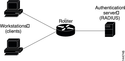
802.1x port-based authentication uses the following device roles:

  • Client—The workstation requesting access to the VPN. It must be running 802.1x-compliant client software, such as that offered with the Microsoft Windows XP operating system.

  • Authentication server—Authenticates clients. The authentication server validates the client’s identity and notifies the router whether the client is authorized to access the network. The Remote Authentication Dial-In User Service (RADIUS) security system with EAP extensions is the only supported authentication server. In Security Manager, a AAA (authentication, authorization, and accounting) server, as defined in a AAA server object, is the authentication server for 802.1x policies.

  • Router (edge router or wireless access point)—Controls physical access to the network based on the authentication status of the client. The router is an intermediary (proxy) between the client and the authentication server, requesting identity information from the client, verifying that information with the authentication server, and relaying a response to the client. In Security Manager, the router on which you configure an 802.1x policy acts as the switch.

Related Topics

802.1x Interface Authorization States

When you use 802.1x, the interface state determines whether to grant the client network access. By default, the interface starts in the unauthorized state. While in this state, the interface disallows all traffic in both directions, except for EAPOL packets. After a client is authenticated, the interface transitions to the authorized state, enabling all client traffic to flow normally.

If a client that does not support 802.1x is connected to an unauthorized 802.1x interface, the router requests the client’s identity. In this situation, the client does not respond to the request, the interface remains in the unauthorized state, and the client is not granted access to the network. In contrast, when an 802.1x-enabled client connects to an interface that is not running the 802.1x protocol, the client initiates the authentication process by sending the EAPOL-Start frame. If no response is received, the client sends the request a fixed number of times. Because no response is received, the client begins sending frames as if the interface were in the authorized state.

You can control the interface authorization state by selecting one of the following options:

  • Auto—Enables 802.1x authentication, which causes the interface to start in the unauthorized state. Only EAPOL frames are sent and received through the interface. Authentication begins when the link state of the interface transitions from down to up or when an EAPOL-Start frame is received. The router requests the client’s identity and begins relaying authentication messages between the client and the authentication server. The router uses the MAC address of each client trying to access the network as unique client identifiers.

  • Force authorized—Disables 802.1x authentication, which causes the interface to move to the authorized state without authenticating the client.

After a client is successfully authenticated, the interface state changes to authorized, which enables all frames from the client to enter the network. If authentication fails, the interface remains in the unauthorized state, but authentication can be retried. If the authentication server cannot be reached, the router can retransmit the request. If the authentication server does not respond after the defined number of attempts, authentication fails and network access is denied to the client.

When a client logs off, it sends an EAPOL-Logoff message, which causes the interface to return to the unauthorized state.

Related Topics

Topologies Supported by 802.1x

802.1x port-based authentication supports two topologies:

  • Point-to-point

  • Wireless LAN

In a point-to-point configuration, only one client can be connected to the 802.1x-enabled interface. The router detects the client when the interface state changes from down to up. If a client leaves the network or is replaced by another client, the interface state changes from up to down, which returns the interface to the unauthorized state.

Figure 1. 802.1x Topology

In a wireless LAN configuration, the 802.1x interface is configured in multihost mode, which is authorized as soon as one client is authenticated. After the interface is authorized, all other clients indirectly attached to the interface are granted access to the network. If the port becomes unauthorized (either because reauthentication fails or an EAPOL-Logoff message is received), the router denies access to the network to all attached clients. In this topology, the wireless access point is a client to the router and is responsible for authenticating the clients attached to it.

Related Topics

Defining 802.1x Policies

You configure an 802.1x policy by defining:

  • The AAA server group containing the AAA server that authenticates hosts that are trying to connect to the network.

  • The virtual interface that carries unauthenticated traffic and the physical interface that carries authenticated traffic.

  • (Optional) Properties of the physical interface, including the control type, automatic reauthentication, and several timeout values.

If the router on which you are defining the 802.1x policy is not part of a VPN (for example, if it is directly connected to the corporate network to which you want to restrict access), you must manually define an access list. You can do this by defining an access rules policy (see Understanding Access Rules).

Before You Begin

  • Configure the selected router with a DHCP policy that contains two IP address pools, one for authenticated clients and one for unauthenticated clients. See Defining DHCP Policies.

  • Make sure the router can route packets to the configured AAA (RADIUS) server. You can verify this by pinging the server from the router.

Related Topics

Procedure


Step 1

Do one of the following:

  • (Device view) Select Platform > Identity > 802.1x from the Policy selector.

  • (Policy view) Select Router Platform > Identity > 802.1x from the Policy Type selector. Select an existing policy or create a new one.

The 802.1x page is displayed. See Table 1 for a description of the fields on this page.

Step 2

Enter the name of the AAA server group containing the AAA server to use for authenticating clients using 802.1x, or click Select to select a server group from a list or to create a new one. The selected AAA server must use RADIUS with EAP extensions.

Note

 
Each AAA server in the selected group must be configured to communicate with an interface that exists on the router; otherwise, validation fails.

Step 3

In the Virtual Template field, enter the name of the interface or interface role that serves as the untrusted, virtual interface for carrying unauthenticated traffic, or click Select to select an interface role from a list or to create a new role. For more information, see Specifying Interfaces During Policy Definition.

Note

 
Integrated Services Routers (ISRs), such as the Cisco 800, 1800, 1900, 2800, 2900, 3800, and 3900 Series, automatically use VLANs to carry unauthenticated traffic. If you define a virtual template, however, it is used in place of the VLAN.

Note

 
Deployment might fail if PPP is defined on the virtual template defined here. See Defining PPP Connections.

Step 4

Enter the name of the interface or interface role that serves as the trusted, physical interface for carrying authenticated traffic, or click Select to select a role from a list.

The interface role you select should represent the internal protected interface that was configured as part of the VPN topology and no other physical interface on the selected router. For more information, see Defining the Endpoints and Protected Networks.

Step 5

(Optional) Modify the defaults of the physical interface used for 802.1x authentication. See Table 1 for details.


802.1x Policy Page

Use the 802.1x policy page to create policies that limit VPN access to authorized users. Authenticated traffic is allowed to pass through a designated physical interface on the router. Unauthenticated traffic is allowed to pass through a virtual interface to the Internet but is not allowed to access the VPN.

For more information, see Defining 802.1x Policies.


Note


802.1x policies require DHCP address pools in order to assign IP addresses to clients. You define these pools by defining a DHCP policy on the same router. See DHCP Policy Page.

Navigation Path

  • (Device view) Select Platform > Identity > 802.1x from the Policy selector.

  • (Policy view) Select Router Platform > Identity > 802.1x from the Policy Type selector. Right-click 802.1x to create a policy, or select an existing policy from the Shared Policy selector.

Related Topics

Field Reference

Table 1. 802.1x Page

Element

Description

AAA Server Group

The RADIUS AAA server group that authenticates the credentials of users trying to access a VPN tunnel. Enter the name of a AAA server group object, or click Add to select one from a list or to create a new AAA server group object.

Note

 
Each AAA server in the selected group must be configured to communicate with an interface that exists on the router; otherwise, validation fails.

Virtual Template

Mandatory for all routers except Integrated Services Routers (ISRs).

The untrusted, virtual interface that provides Internet access to unauthenticated traffic. Enter the name of an interface or interface role, or click Select to select one from a list or to create a new group object.

Note

 
You do not need to configure a virtual template for ISRs, because they automatically use VLANs to provide access. If you do define a virtual template, however, it is used instead of the VLAN.

Note

 
Deployment might fail if PPP is defined on the virtual template defined here. See PPP Dialog Box—PPP Tab.

Interface

The trusted, physical interface that provides VPN access to authenticated traffic. Enter the name of an interface or interface role, or click Select to select one from a list or to create a new group object.

If you use an interface role, the pattern defined in the interface role must represent only one physical interface on the selected device. This interface should be the internal protected interface that you configured as part of the VPN topology. For more information, see Defining the Endpoints and Protected Networks.

Number of retries

The number of times the physical interface resends an Extensible Authentication Protocol (EAP) request/identity frame to a client if a response is not received before restarting authentication.

Valid values range from 1 to 10. The default is 2.

Note

 
You should change the default only to adjust for unusual circumstances, such as unreliable links or specific problems with certain clients and authentication servers.

Control type

The control state of the interface, which determines whether the host is granted access to the network. Options are:

  • Force Authorize—Disables 802.1x authentication and causes the interface to move to the authorized state without requiring any authentication exchange. This means the interface transmits and receives normal traffic without 802.1x-based authentication of the host. This is the default.

  • Auto—Enables 802.1x authentication and causes the interface to begin in the unauthorized state, allowing only EAPOL frames to be sent and received through the interface. If a host is successfully authenticated, the interface state changes to authorized, which enables all frames from the host through the interface.

Enable client reauthentication

When selected, enables periodic reauthentication of client PCs on the 802.1x interface. Reauthentication is performed after the interval defined in the Client reauthentication period timeout field. The default period is 3600 seconds (1 hour).

When deselected, periodic reauthentication is not performed.

Client reauthentication period timeout

Applies only when the Enable client reauthentication check box is selected.

The number of seconds between client reauthentication attempts. Valid values range from 1 to 65535 seconds. The default is 3600 seconds (1 hour).

Quiet period

The amount of time the router remains in a quiet state after a failed authentication exchange with the client. Authentication exchanges might fail, for example, because the client provided an invalid password.

Valid values range from 1 to 65535 seconds. The default is 120 seconds.

Note

 
Entering a value smaller than the default provides a faster response time to the user.

Rate Limit period

The interval after which the interface throttles the EAP-Start packets it receives from malfunctioning client PCs. Use this setting, called rate limiting, to prevent these clients from wasting router processing power.

Valid values range from 1 to 65535 seconds. By default, rate limiting is disabled.

Note

 
To disable an existing rate limit, delete the value defined in this field and leave the field blank.

AAA Server timeout

The number of seconds the router waits before retransmitting packets to the AAA server. If the router sends an 802.1x packet to the AAA server and the server does not respond, the router sends another packet after this interval elapses.

Valid values range from 1 to 65535 seconds. The default is 30 seconds.

Supplicant period

The number of seconds the router waits before retransmitting EAP-Request/Identity packets to the supplicant (client PC). If the router sends an EAP-Request/Identity packet to the client PC (supplicant) and the supplicant does not respond, the router sends the packet again after this interval elapses.

Valid values range from 1 to 65535 seconds. The default is 30 seconds.

Network Admission Control on Cisco IOS Routers


Note


From version 4.17, though Cisco Security Manager continues to support IOS features/functionality, it does not support any bug fixes or enhancements.

Network Admission Control (NAC), an industry initiative sponsored by Cisco Systems, uses the network infrastructure to enforce security-policy compliance on all devices seeking to access network computing resources, thereby limiting damage from viruses and worms. By using NAC, organizations can provide network access to endpoint devices such as PCs, PDAs, and servers that are verified to be fully compliant with established security policy. NAC can also identify noncompliant devices and deny them access, place them in a quarantined area, or give them restricted access to computing resources.

Network access decisions are made through a process of posture validation, which evaluates the posture credentials presented by the endpoint device. These credentials can include such information as the endpoint’s antivirus state, operating system version, operating system patch level, or Cisco Security Agent version and settings.

You can use NAC to enforce security policy compliance in many types of deployments, including branch offices, remote access, and dial-in access.

NAC policies in Security Manager enable a Cisco IOS router to act as a Network Access Device (NAD) for enforcing policy compliance on devices seeking to access the network. The following topics describe additional details about NAC:

The following topics describe the tasks you perform to create NAC policies on Cisco IOS routers:

Router Platforms Supporting NAC

To configure NAC policies on a router, the router must be running Cisco IOS Software Release 12.3(8)T images and later (with the Advanced Security feature set). However, the following routers do not support NAC:

  • Cisco 7600 Series (7603, 7604, 7606, 7609, 7613)

  • Cisco 7300 Series (7301, 7304)

  • Cisco 7100 Series VPN Routers (7120, 7140, 7160)

  • Cisco 3600 Series Multiservice Platforms (3620, 3631, 3661, 3662)

  • Cisco 1700 Series Modular Access Routers (1710, 1720, 1750)

  • Cisco 1600 Series (1601, 1602, 1603, 1604, 1605)

  • Cisco ASR 1000 Series Aggregation Services Routers (all models)

  • Cisco 800 Series (801, 803, 805, 811, 813, 828, 851, 857, 871, 876, 877, 878)

  • Cisco SOHO 90 Series Secure Broadband Routers (91, 96, 97)

  • Cisco SOHO 77 Series (71, 76, 77 ADSL, 77 H ADSL, 78)

Understanding NAC Components

NAC contains the following components:

  • Cisco Trust Agent (CTA)—The CTA acts as the NAC client. It provides posture credentials for the endpoint device on which it is installed, including the type of operating system and the version of antivirus software installed.

  • Network access device (NAD)—The NAD initiates posture validation with the CTA when its Intercept ACL is triggered. It relays posture credentials received from the CTA to a AAA server. In return, the NAD receives configuration information from the AAA server, which it enforces on the selected interface. The NAD also:

    • Periodically polls the CTA to confirm that it is communicating with the same client at this IP address.

    • Revalidates all current sessions.

    • Sends username and password information from devices lacking a CTA (clientless hosts) to the AAA server for authentication.

    • Supports an exception list of predefined actions applied to specific devices, based on the device IP address or MAC address.

When you configure NAC policies in Security Manager, you are configuring the behavior of the Cisco IOS router acting as the NAD.

  • AAA server—The AAA server obtains and validates posture credentials received from the CTA and returns the access policy to be enforced on the NAD. The AAA server must be a Cisco Secure Access Control Server (ACS), running the RADIUS protocol. Existing ACS authorization support can be used to provide access to clientless hosts. Posture validation rules and the access policies resulting from those rules are configured on the ACS.

Related Topics

Understanding NAC System Flow

As shown in NAC System Flow, the system flow for NAC is:

  1. An IP packet from a connecting device triggers the Intercept ACL configured on the NAD.

  2. The NAD triggers posture validation with the CTA configured on the device using the Extensible Authentication Protocol over User Datagram Protocol, otherwise known as EAP over UDP, or simply EoU.

  3. The CTA sends its posture credentials to the NAD using EAP over UDP.

  4. The NAD sends these posture credentials to the ACS using RADIUS.

  5. The ACS performs posture validation, which determines whether to allow the device to access the network. (If necessary, the ACS requests additional posture validation from a third-party server. For example, if the CTA forwards credentials that are specific to a particular antivirus application, the ACS forwards this information via the HCAP protocol to a vendor server for validation.) If the device is a clientless host, the ACS checks the username and password it receives against its locally stored list.

  6. The ACS directs the NAD to enforce the appropriate access policy on the requesting device. Access may be granted, denied, redirected, or restricted.

Figure 2. NAC System Flow

Related Topics

Defining NAC Setup Parameters

You configure NAC setup parameters by selecting the AAA server groups that obtain and validate the posture credentials received from devices trying to connect to the network. You can configure an option that allows devices lacking the Cisco Trust Agent (CTA) to be authenticated by a predefined username and password stored on a Cisco Secure Access Control Server (ACS). Additionally, you can modify default settings for EAP over UDP. This is the protocol used for posture validation communications between the Cisco IOS router serving as the network access device (NAD) and the device trying to access your network.

Related Topics

Procedure


Step 1

Do one of the following:

  • (Device view) Select Platform > Identity > Network Admission Control from the Policy selector, then click the Setup tab in the work area.

  • (Policy view) Select Router Platform > Identity > Network Admission Control from the Policy Type selector. Select an existing policy or create a new one, and then click the Setup tab.

The NAC Setup tab is displayed. See Table 1 for a description of the fields on this tab.

Step 2

Enter the name of the AAA server group containing the AAA server that performs posture validation, or click Select to select the server group from a list or to create a new one. The selected AAA server group must contain ACS devices running RADIUS.

Note

 
Each AAA server in the selected group must be configured to communicate with an interface that exists on the router; otherwise, validation fails.

Step 3

(Optional) Select up to two AAA server groups as backups to the main server group. If all the servers in the main server group go down, the servers in the backup server group perform NAC.

Both backup server groups must consist of ACS devices running RADIUS.

Step 4

(Optional) Under EAP over UDP, select one or both of the following Allow parameters:

  1. Select the Allow IP Station ID check box to include IP addresses in the RADIUS requests sent to the ACS.

  2. Select the Allow Clientless check box to provide access to devices that do not have the CTA installed. In such cases, the ACS authenticates these devices by checking the username and password against a predefined list.

    If you do not select this check box, devices without CTA are prevented from accessing the network if their traffic matches the Intercept ACL. This is because without CTA, posture validation cannot be performed.

    Note

     
    This feature is not supported on routers running Cisco IOS Software Release 12.4(6)T or later.

Step 5

(Optional) Under EAP over UDP, modify the default settings related to the EAP over UDP (EoU) protocol, if required. See Table 1 for details.


Defining NAC Interface Parameters

You configure NAC interface parameters by selecting the interfaces on which NAC is performed. You must also define the Intercept ACL, which determines which traffic on these interfaces is subject to posture validation. Additionally, you can optionally override the device-level setting for initiating EAP over UDP sessions and subject all sessions to periodic revalidation (see Defining NAC Setup Parameters).

A NAC policy must include at least one interface definition to function.

Before You Begin

Related Topics

Procedure


Step 1

Do one of the following:

  • (Device view) Select Platform > Identity > Network Admission Control from the Policy selector, then click the Interfaces tab in the work area.

  • (Policy view) Select Router Platform > Identity > Network Admission Control from the Policy Type selector. Select an existing policy or create a new one, and then click the Interfaces tab.

The NAC Interfaces tab is displayed. See for a description of the fields on this tab.

Step 2

On the NAC Interfaces tab, select an interface definition from the table, then click Edit, or click Add to create a definition. The NAC Interface Configuration dialog box appears. See NAC Identity Action Dialog Box for a description of the fields in this dialog box.

Step 3

Enter the name of the interface or interface role on which NAC is performed, or click Select to select an interface role from a list or to create a new one. For more information, see Specifying Interfaces During Policy Definition.

Step 4

(Optional) Enter the name of the ACL object that acts as the intercept ACL, or click Select to select it from a list or to create a new object.

The intercept ACL determines which traffic on the selected interfaces is subject to posture validation before being granted access to the network. If you do not select an ACL, all traffic on the selected interfaces is subject to posture validation.

Note

 
If you defined an authentication proxy on the same interface as a NAC interface, you must use the same intercept ACL in both policies. Otherwise, deployment might fail. For more information about authentication proxies, see Configuring AAA Rules for IOS Devices.

Step 5

(Optional) To override the device-level value defined for maximum attempts to initiate an EAP over UDP session, enter a new value in the EAP over UDP Max Retries field.

Step 6

(Optional) Deselect the Enable EOU Session Revalidation check box if you do not want the NAD to periodically revalidate all EAP over UDP sessions.

Note

 
Subinterfaces support default values only for the options described in Step 5 and Step 6.

Step 7

Click OK to save your definitions locally on the client and close the dialog box. Your interface definitions appear in the table on the NAC Interfaces tab.


Defining NAC Identity Parameters

By default, any traffic over the selected interfaces that match the intercept ACL is subjected to posture validation before it is permitted to enter the network. However, you can create an exception list of predefined actions to apply to specific devices. You use identity profiles to create this exception list. Each profile contains two elements:

  • A profile definition, identifies the device to which the profile applies. Devices can be identified by their IP addresses, MAC addresses, or types (for Cisco IP phones).

  • An action, which defines the result when this device tries to access the network. Each action can include an ACL, a redirect URL, or both. If you do not specify an action, the default ACL is applied.

When you configure NAC identity parameters, you first define one or more identity actions and then create the identity profiles to which these actions apply. You can apply each action to multiple profiles.

Related Topics

Procedure


Step 1

Do one of the following:

  • (Device view) Select Platform > Identity > Network Admission Control from the Policy selector, then click the Identities tab in the work area.

  • (Policy view) Select Router Platform > Identity > Network Admission Control from the Policy Type selector. Select an existing policy or create a new one, and then click the Identities tab.

The NAC Identities tab is displayed. See Table 1 for a description of the fields on this tab.

Step 2

Define one or more identity actions:

  1. On the NAC Identities tab, select an identity action from the lower table, then click Add. The NAC Identity Action dialog box appears.

  2. Define an identity action. See Table 1 for a description of the available fields.

  3. Click OK to save your definitions and close the dialog box. The action appears in the Identity Actions table in the NAC Identities tab.

  4. (Optional) Repeat 2.a through 2.c to define additional identity actions, as required.

Step 3

Define identity profiles:

  1. Select an identity profile from the upper table on the NAC Identities tab, then click Add. The NAC Identity Profile dialog box appears. See Table 1 for a description of the fields in this dialog box.

  2. Enter the name of an identity action (as defined in Step 2) or click Select to display a selector.

  3. Select and define a profile definition, which identifies the device to which the profile should apply.

  4. Click OK to save your definitions and close the dialog box. The profile appears in the Identity Profiles table in the NAC Identities tab.

  5. (Optional) Repeat 3.a through 3.d to define additional identity profiles, as required.


Network Admission Control Policy Page

Network Admission Control (NAC) policies enable Cisco IOS routers acting as network access devices (NADs) to enforce access privileges when an endpoint tries to connect to a network. Access decisions are made on the basis of information provided by the endpoint device, such as its current antivirus state, thus keeping insecure nodes from infecting the network.

You can configure NAC policies on a Cisco IOS router from the following tabs on the Network Admission Control policy page:

For more information, see Network Admission Control on Cisco IOS Routers.

Navigation Path

  • (Device view) Select Platform > Identity > Network Admission Control from the Policy selector.

  • (Policy view) Select Router Platform > Identity > Network Admission Control from the Policy Type selector. Right-click Network Admission Control to create a policy, or select an existing policy from the Shared Policy selector.

Network Admission Control Page—Setup Tab

Use the Network Admission Control Setup tab to select the Cisco Secure Access Control Servers used for authentication during the NAC process, as well as to define the EAP over UDP settings for communications between the NAD and the client seeking access to the network.

Navigation Path

Go to the Network Admission Control Policy Page, then click the Setup tab.

Related Topics

Field Reference

Table 2. Network Admission Control Setup Tab

Element

Description

AAA Server Group

The AAA server group used for NAC authentication. You must select a server group consisting of Cisco Secure Access Control Server (ACS) devices running the RADIUS protocol. Enter the name of a AAA server group object, or click Select to select the object from a list or to create a new one.

Note

 
Each AAA server in the selected group must be configured to communicate with an interface that exists on the router; otherwise, validation fails.

Backup AAA Server Group 1

The backup AAA server group in case the AAA servers in the main group are down.

Backup AAA Server Group 2

The secondary backup AAA server group in case the AAA servers in the main group and the first backup group are down.

EAP over UDP (EoU) settings

Allow IP Station ID

When selected, enables an IP address to be included in the calling-station-id field of RADIUS requests sent to the ACS.

When deselected, IP addresses are not included in the calling-station-id field of RADIUS requests sent to the ACS.

Allow Clientless

When selected, enables devices that do not have the Cisco Trust Agent (CTA) installed to be authenticated through the use of a username and password configured on the ACS.

If you select this check box, enter the username and password (including confirmation) in the fields provided.

When deselected, NAC prevents devices lacking the CTA from accessing the network, if their traffic matches the intercept ACL (see NAC Interface Configuration Dialog Box).

Note

 
This feature is not supported on routers running Cisco IOS Software Release 12.4(6)T or later.

Max Retry

The maximum number of retries that all NAC interfaces on this router should make when initiating an EAP over UDP session with a connecting device.

Valid values range from 1 to 3. The default is 3.

Note

 
You can override this global value on a specific interface, if required. SeeNetwork Admission Control Page—Interfaces Tab .

Rate Limit

The number of EAP over UDP posture validations that the router can handle simultaneously. Additional devices cannot be validated until one or more devices drop off.

Valid values range from 1 to 200. The default is 20. If you set this value to 0, rate limiting is turned off.

Port

The UDP port to use for EAP over UDP sessions.

Valid values range from 1 to 65535. The default is 21862.

Note

 
For NAC to work, the default ACL on this router must permit UDP traffic over the port designated here for EAP over UDP traffic. For more information, see Understanding Access Rules.

Enable Logging

When selected, EAP over UDP events on this router are logged to the device.

When deselected, EAP over UDP logging is disabled. This is the default.

Network Admission Control Page—Interfaces Tab

Use the Network Admission Control Interfaces tab to select and configure the router interfaces on which to perform NAC. This includes configuring the Intercept ACL and selected EoU interface parameters. A NAC policy must include at least one interface definition in order to function.

Navigation Path

Go to the Network Admission Control Policy Page, then click the Interfaces tab.

Related Topics

Field Reference

Table 3. Network Admission Control Interfaces Tab

Element

Description

Interfaces

The name of the interface on which NAC is being performed.

Intercept ACL

The name of the Intercept ACL, which determines the incoming traffic that triggers the interface to make a posture validation check.

EoU Max Retries

The maximum number of retries that this interface should perform when it initializes an EoU session with a connecting device.

Revalidate

Indicates whether the interface revalidates its EoU sessions to make sure they are still active.

Add button

Opens the NAC Interface Configuration Dialog Box. From here you can define a NAC interface.

Edit button

Opens the NAC Interface Configuration Dialog Box. From here you can edit the selected NAC interface.

Delete button

Deletes the selected NAC interfaces from the table.

NAC Interface Configuration Dialog Box

Use the NAC Interface Configuration dialog box to add or edit the router interfaces on which NAC is being performed.

Navigation Path

Go to the Network Admission Control Page—Interfaces Tab, then click the Add or Edit button beneath the table.

Related Topics
Field Reference
Table 4. NAC Interface Configuration Dialog Box

Element

Description

Interface

The interface that will perform NAC on connecting devices. Enter the name of an interface or interface role, or click Select to select an object from a list or to create a new one.

Intercept ACL

The ACL that defines the traffic requiring posture validation. Enter the name of an ACL object, or click Add to select an object from a list or to create a new one.

Note

 
If an authentication proxy is configured on the same interface as NAC, the same Intercept ACL must be used in both policies. Otherwise, deployment may fail. For more information about authentication proxies, see Configuring AAA Rules for IOS Devices.

EAP over UDP Max Retries

The maximum number of times that the router should try to initiate an EoU session with a connecting device. Valid values range from 1 to 3. The default is 3.

Note

 
Subinterfaces support the default value only.

Enable EoU Session Revalidation

When selected, the router revalidates its EoU sessions as required. This is the default.

When deselected, EoU session revalidation is not performed.

Note

 
Subinterfaces support the default value only.

Network Admission Control Page—Identities Tab

Use the Network Admission Control Identities tab to view, create, edit, and delete NAC identity profiles and identity actions. Identity profiles define a specific action to perform on traffic received from selected devices, as identified by their IP address, MAC address, or device type. In this way, devices with identity profiles are handled by NAC without having to undergo posture validation against an ACS.

Navigation Path

Go to the Network Admission Control Policy Page, then click the Interfaces tab.

Related Topics

Field Reference

Table 5. Network Admission Control Identities Tab

Element

Description

Identity Profiles Table

Profile Definition

The type of identity profile—device IP address, MAC address, or device type (IP phone).

Action Name

The name of the action (defined in the Identity Actions table) that is assigned to this NAC identity profile.

Add button

Opens theNAC Identity Profile Dialog Box. From here you can define an identity profile.

Edit button

Opens the NAC Identity Profile Dialog Box. From here you can edit a selected identity profile.

Delete button

Deletes the selected identity profiles from the table.

Identity Actions Table

Action Name

The name of the identity action.

ACL

The ACL applied to profiles to which this identity action is assigned.

Redirect URL

The URL to which traffic from devices to which this identity action is assigned are redirected.

Add button

Opens the NAC Identity Action Dialog Box for defining a NAC identity action.

Edit button

Opens the NAC Identity Action Dialog Box for editing a selected NAC identity action.

Delete button

Deletes the selected identity actions from the table.

NAC Identity Profile Dialog Box

Use the NAC Identity Profile dialog box to add or edit the NAC profiles assigned to devices that match a specific identity. Identity profiles define a NAC action to apply to all traffic coming from a specific device, based on its IP address, MAC address, or device type (for IP phones).

Navigation Path

Go to the Network Admission Control Page—Identities Tab, then click the Add or Edit button beneath the Identity Profiles table.

Related Topics
Field Reference
Table 6. NAC Identity Profile Dialog Box

Element

Description

Action Name

The name of the action to assign to the profile. Enter the name of an action, or click Select to display a selector. For more information about creating actions, see NAC Identity Action Dialog Box.

Profile Definition

The device to which this profile is assigned:

  • IP Address—The IP address of the device to which this profile should be assigned. The same IP address cannot be used in more than one profile.

  • MAC Address—The MAC address of the device to which this profile should be assigned.

  • Cisco IP Phone—Used when defining a NAC identity profile for Cisco IP phones.

NAC Identity Action Dialog Box

Use the NAC Identity Action dialog box to add or edit the actions assigned to NAC identity profiles.

Navigation Path

Go to the Network Admission Control Page—Interfaces Tab, then click the Add or Edit button beneath the Identity Actions table.

Related Topics
Field Reference
Table 7. NAC Identity Action Dialog Box

Element

Description

Name

A descriptive name for the identity action. Use this name when you select an action to assign to a NAC identity profile. See NAC Identity Action Dialog Box.

Access Control Lists

The ACL that defines how to handle traffic received from a device which is assigned a profile that includes this action. Enter the name of an ACL object, or click Add to select an object from a list or to create a new one.

Note

 
You cannot select the same ACL object that is being used for the intercept ACL. See NAC Interface Configuration Dialog Box.

Redirect URL

The address of the remediation server to which traffic from the device should be redirected. Redirect URLs are usually of the form http://URL or https://URL.