Quality of Service on Cisco IOS Routers
 Note |
From version 4.17, though Cisco Security Manager continues to support IOS features/functionality, it does not support any bug fixes or enhancements. |
Quality of service (QoS) refers to the ability of a network to provide priority service to selected network traffic over various underlying technologies, including Frame Relay, ATM, Ethernet and 802.1 networks, SONET, and IP-routed networks. QoS features enhance the predictability of network service by:
-
Supporting dedicated bandwidth.
-
Improving loss characteristics.
-
Avoiding and managing network congestion.
-
Shaping network traffic.
-
Setting traffic priorities across the network.
QoS is generally used at entry points to service providers, as well as at consolidation points where multiple lines converge. QoS is also useful where speed mismatches occur (for example, at the boundary between a WAN and a LAN), as these places are often traffic congestion points.
QoS policies in Security Manager are based on the Cisco Systems Modular QoS CLI (MQC). MQC standardizes the CLI and semantics for QoS features across all platforms supported by Cisco IOS software, which provides a modular and highly extensible framework for deploying QoS. Security Manager provides an easy-to-use interface for MQC that concentrates key QoS features inside a single dialog box, streamlining the creation of QoS policies for selected traffic entering and leaving the router.
For a description of the procedure for defining a QoS policy in Security Manager, see Defining QoS Policies.
Related Topics
Quality of Service and CEF
Cisco Express Forwarding (CEF) is an advanced Layer 3 IP switching technology that optimizes network performance and scalability for all kinds of networks. It defines the fastest method by which a Cisco IOS router forwards packets from ingress to egress interfaces.
Certain QoS features configurable in Security Manager, such as Class-Based Policing and Class-Based Weighted Random Early Detection, are supported only on routers that run CEF. All routers from the Cisco 800 Series to the Cisco 7200 Series require CEF for these QoS features; the Cisco 7500 Series requires distributed CEF (dCEF).
Note |
For a complete list, see When is CEF Required for Quality of Service on Cisco.com at this URL: http://www.cisco.com/en/US/tech/tk39/tk824/technologies_tech_note09186a0080094978.shtml |
By default, CEF is enabled as part of the router’s initial configuration. To verify whether CEF is enabled on your router, use the show ip cef command. You can configure CEF using the CEF interface settings policy (see CEF Interface Settings on Cisco IOS Routers). Be aware, however, that if your router does not have CEF enabled, activating CEF could have a significant impact on your router’s packet streaming. Consult your router documentation before enabling CEF.
Related Topics
Understanding Matching Parameters
You define matching parameters by identifying the traffic on which QoS is performed, that is, classifying the interesting packets. Various classification tools are available, including protocol type, IP precedence (IPP) value, Differentiated Service Code Point (DSCP) value, and ACLs.
Traffic classes consist of a series of match criteria and a means of evaluating these criteria. For example, you might define a class with matching criteria based on several specified protocols and a DSCP value. You can then specify that a packet must match only one of these defined criteria to be considered part of this class. Your other option is to specify that packets must match all defined criteria considered part of the traffic class.
Packets that are members of a defined traffic class are forwarded according to the QoS specifications that you defined in the policy map. Packets that fail to meet any of the matching criteria are classified as members of the default traffic class.
For information about defining matching parameters in a QoS policy, see Defining QoS Class Matching Parameters.
Related Topics
Understanding Marking Parameters
Marking parameters enable you to classify packets, which entails using a traffic descriptor to categorize a packet within a specific group. This defines the packet and makes it accessible for QoS handling on the network. Both traffic policers and traffic shapers use the packet classification to ensure adherence to the contracted level of service agreed upon between the source and your network. Additionally, marking parameters enable you to take packets that might have arrived at the device with one QoS classification and reclassify them. Downstream devices use this new classification to identify the packets and apply the appropriate QoS functions to them.
Security Manager uses two types of marking for IPv4 packets—one based on IPP classes and one based on DSCP values. IPP is based on the three most significant bits in the Type of Service (ToS) byte of each packet, which means you can partition traffic into eight classes. For historical reasons, each precedence value corresponds with a name, as defined in RFC 791. Table 1 lists the numbers and their corresponding names, from least to most important.
|
Class |
Name |
|---|---|
|
0 |
routine |
|
1 |
priority |
|
2 |
immediate |
|
3 |
flash |
|
4 |
flash-override |
|
5 |
critical |
|
6 |
internet |
|
7 |
network |
Note |
Classes 6 and 7 are generally reserved for network control information, such as routing updates. |
DSCP is based on the six most significant bits in the ToS byte (the remaining two bits are used for flow control), with values ranging from 0 to 63. The DSCP bits contains the IPP bits, which makes DSCP backward-compatible with IPP.
Marking is generally used on devices that are close to the network edge or administrative domain so that subsequent devices can provide service based on the classification mark.
For information about defining marking parameters in a QoS policy, see Defining QoS Class Marking Parameters.
Related Topics
Understanding Queuing Parameters
Queuing manages congestion on traffic leaving a Cisco IOS router by determining the order in which to send packets out over an interface, based on priorities you assign to those packets. Queuing makes it possible to prioritize traffic to satisfy time-critical applications, such as desktop video conferencing, while still addressing the needs of less time-dependent applications, such as file transfer.
During periods of light traffic, that is, when no congestion exists, packets are sent out as soon as they arrive at an interface. However, during periods of transmission congestion at the outgoing interface, packets arrive faster than the interface can send them. By using congestion management features such as queuing, packets accumulating at the interface are queued until the interface is free to send them. They are then scheduled for transmission according to their assigned priority and the queuing mechanism configured for the interface. The router determines the order of packet transmission by controlling which packets are placed in which queue and how queues are serviced with respect to one another.
Security Manager uses a form of queuing called Class-Based Weighted Fair Queuing (CBWFQ). With CBWFQ, you define traffic classes based on match criteria. Packets matching the criteria constitute the traffic for this class. A queue is reserved for each class, containing the traffic belonging to that class. You assign characteristics to queues, such as the bandwidth (fixed or minimum) assigned to it and the queue limit, which is the maximum number of packets allowed to accumulate in the queue.
When you use CBWFQ, the sum of all bandwidth allocation on an interface cannot exceed 75 percent of the total available interface bandwidth. The remaining 25 percent is used for other overhead, including Layer 2 overhead, routing traffic, and best-effort traffic. Bandwidth for the CBWFQ default class, for instance, is taken from the remaining 25 percent.
For more information about queuing, see:
For information about defining queuing parameters in a QoS policy, see Defining QoS Class Queuing Parameters.
Related Topics
Tail Drop vs. WRED
After a queue reaches its configured queue limit, the arrival of additional packets causes tail drop or packet drop to take effect, depending on how you configured the QoS policy. Tail drop, which is the default response, treats all traffic equally and does not differentiate between different classes of service. When tail drop is in effect, packets are dropped from full queues until the congestion is eliminated and the queue is no longer full. This often leads to global synchronization, in which a period of congestion is followed by a period of underutilization, as multiple TCP hosts reduce their transmission rates simultaneously.
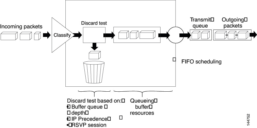
A more sophisticated approach to managing queue congestion is offered by Cisco’s implementation of Random Early Detection, called Weighted Random Early Detection, or WRED. As shown in Weighted Random Early Detection, WRED reduces the chances of tail drop by selectively dropping packets when the output interface begins to show signs of congestion. By dropping some packets early instead of waiting until the queue is full, WRED avoids dropping large numbers of packets at once and allows the transmission line to be used fully at all times.
WRED is useful only when the bulk of the traffic is TCP/IP traffic, because TCP hosts reduce their transmission rate in response to congestion. With other protocols, packet sources might not respond, or might resend dropped packets at the same rate. As a result, dropping packets does not decrease congestion.
Note |
WRED treats non-IP traffic as precedence 0, the lowest precedence value. Therefore, non-IP traffic is more likely to be dropped than IP traffic. |
Related Topics
Low-Latency Queuing
The low-latency queuing (LLQ) feature brings strict priority queuing to CBWFQ. Strict priority queuing gives delay-sensitive data, such as voice traffic, preference over other traffic.
Note |
Although it is possible to assign various types of real-time traffic to the strict priority queue, we strongly recommend that you direct only voice traffic to it. |
LLQ defines the maximum bandwidth that you can allocate to priority traffic during times of congestion. Setting a maximum ensures that nonpriority traffic does not starve (meaning that this traffic is also provided with bandwidth). When the device is not congested, the priority class traffic is allowed to exceed its allocated bandwidth. Policing drops packets from the priority queue; therefore, neither WRED nor tail drop (as configured in the Queue Limit field) is used.
When LLQ is not used, CBWFQ provides weighted fair queuing based on defined classes, with no strict priority queue available for real-time traffic.
Related Topics
Default Class Queuing
You use the Fair Queue field to define the number of dynamic queues that should be reserved for the default class to use. This is the class to which traffic that does not satisfy the match criteria of other classes is directed. By default, the number of queues that are created is based on the interface bandwidth.
Table 1 lists the default number of dynamic queues that CBWFQ uses when it is enabled on an interface:
|
Bandwidth Range |
Number of Dynamic Queues |
|---|---|
|
Less than or equal to 64 kbps |
16 |
|
More than 64 kbps and less than or equal to 128 kbps |
32 |
|
More than 128 kbps and less than or equal to 256 kbps |
64 |
|
More than 256 kbps and less than or equal to 512 kbps |
128 |
|
More than 512 kbps |
256 |
Related Topics
Understanding Policing and Shaping Parameters
Security Manager offers two kinds of traffic regulation mechanisms:
-
The rate-limiting feature of Class-Based Policing for policing traffic. Policing limits traffic flow to a configured rate. Policing can be performed on a selected interface or on the control plane. See Understanding Control Plane Policing.
-
Distributed Traffic Shaping (DTS) for shaping traffic. Traffic shaping enables you to control the traffic leaving an interface (output traffic) in order to match its flow to the speed of the remote target interface and to ensure that the traffic conforms to the policies defined for it. By shaping traffic to meet downstream requirements, you can eliminate bottlenecks in topologies with data-rate mismatches. Shaping can either be performed on selected QoS classes or at the interface level (hierarchical shaping).
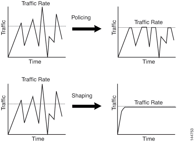
Both policing and shaping mechanisms use the traffic descriptor for a packet—indicated by the classification of the packet (see Understanding Marking Parameters)—to ensure adherence to the agreed upon level of service. Although policers and shapers usually identify traffic descriptor violations in the same way, they differ in the way they respond to violations, as shown in Traffic Policing vs. Traffic Shaping:
-
A policer typically drops excess traffic. In other cases, it transmits the traffic with a different (usually lower) priority.
-
A shaper typically delays excess traffic using a buffer, or queuing mechanism, to hold packets and shape the flow when the data rate of the source is later than expected.
For information about defining policing and shaping parameters in a QoS policy, see Defining QoS Class Policing Parameters and Defining QoS Class Shaping Parameters.
Related Topics
Understanding the Token-Bucket Mechanism
Both policing and shaping use a token-bucket mechanism to regulate data flow. A token bucket is a formal definition of a rate of transfer. It has three components: a burst size, a mean rate, and a time interval (Tc). Any two values may be derived from the third using this formula:
mean rate = burst size / time interval
These terms are defined as follows:
-
Mean rate—Also called the committed information rate (CIR), it specifies how much data can be sent or forwarded per unit time on average. The CIR is defined either as an absolute value or as a percentage of the available bandwidth on the interface. When defined as a percentage, the equivalent value in bits per second (bps) is calculated after deployment based on the interface bandwidth and the percent value defined in the policy.
Note |
If the interface bandwidth changes (for example, more bandwidth is added), the bps value of the CIR is recalculated based on the revised amount of bandwidth. |
-
Burst size—Also called the committed burst (Bc) size, it specifies for each burst how much data can be sent within a given time without creating scheduling concerns. When you use percentages to calculate the CIR, burst size is measured in milliseconds.
-
Time interval—Also called the measurement interval, it specifies the amount of time in seconds per burst. Over any integral multiple of this interval, the bit rate of the interface does not exceed the mean rate. The bit rate, however, might be arbitrarily fast within the interval.
In the token-bucket metaphor, tokens are put into the bucket at a certain rate. These tokens represent permission for the source to send a certain number of bits into the network. To send a packet, the regulator (policer or shaper) must remove a number of tokens from the bucket that equals the packet size.
Security Manager uses a two-bucket algorithm, as shown in Two-Token Bucket Algorithm. The first bucket is the conform bucket and the second bucket is the exceed bucket. The full size of the conform bucket is the number of bytes specified as the normal burst size. The full size of the exceed bucket is the number of bytes specified in the maximum burst size. Both buckets are initially full, and they are updated based on the token arrival rate, which is determined by the CIR. If the number of bytes in the arriving packet is less than the number of bytes in the conform bucket, the packet conforms. The required number of tokens are removed from the conform bucket and the defined conform action is taken (for example, the packet is transmitted). The exceed bucket is unaffected.
If the conform bucket does not contain sufficient tokens, the excess token bucket is checked against the number of bytes in the packet. If enough tokens are present in the two buckets combined, the exceed action is taken on the packet and the required number of bytes are removed from each bucket. If the exceed bucket contains an insufficient number of bytes, the packet is in violation of the burst limits and the violate action is taken on the packet.
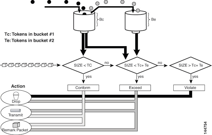
When you use traffic policing, the token-bucket algorithm provides three actions for each packet: a conform action, an exceed action, and an optional violate action. For instance, packets that conform can be configured to be transmitted, packets that exceed can be configured to be sent with a decreased priority, and packets that violate can be configured to be dropped.
Traffic policing is often configured on interfaces at the edge of a network to limit the rate of traffic entering or leaving the network. In the most common traffic policing configurations, traffic that conforms is transmitted and traffic that exceeds is sent with a decreased priority or is dropped. You can change these configuration options to suit your network needs.
When you use traffic shaping, the token-bucket mechanism includes a data buffer for holding packets that cannot be sent immediately. (Policers do not have such a buffer.) The token buckets permit packets to be sent in bursts, but places bounds on this capability so that the flow is never faster than the capacity of the buckets plus the time interval multiplied by the refill rate. The buffer also guarantees that the long-term transmission rate does not exceed the CIR.
Related Topics
Understanding Control Plane Policing
The Control Plane Policing feature enables you to manage input traffic entering the control plane (CP) of the router. The CP is a collection of processes that run at the process level on the route processor. These processes collectively provide high-level control for most Cisco IOS functions. Control plane policing protects the CP of Cisco IOS routers and switches against reconnaissance and denial-of-service (DoS) attacks, enabling the CP to maintain packet forwarding and protocol states despite an attack or heavy traffic load on the router or switch.
The Control Plane Policing feature treats the CP as a separate entity with its own ingress (input) and egress (output) ports, enabling you to use Security Manager to configure QoS policies on input. These policies are applied when a packet enters the CP. You can configure a QoS policy to prevent unwanted packets from progressing after a specified rate limit is reached. For example, a system administrator can limit all TCP/SYN packets that are destined for the CP to a maximum rate of 1 megabit per second. Additional packets beyond this limit are silently discarded.
The following types of Layer 3 packets are forwarded to the CP and processed by aggregate control plane policing:
-
Routing protocol control packets
-
Packets destined for the local IP address of the router
-
Packets from management protocols, such as SNMP, Telnet, and secure shell (SSH).
Note |
Support for output policing is available only in Cisco IOS Release 12.3(4)T and later T-train releases. |
For information about how to define Control Plane Policing, see Defining QoS on the Control Plane. For more information about this feature, refer to the document, Control Plane Policing on Cisco.com at this URL:
http://www.cisco.com/en/US/docs/ios/qos/configuration/guide/ctrl_plane_policng.html
Related Topics
Defining QoS Policies
When you define QoS policies, you must first decide whether to configure the policy on specific interfaces or on the control plane. This initial choice determines how you configure the rest of the policy, as described in the following topics:
Note |
If you define a QoS policy on both the interfaces and the control plane of the same device, only the control plane configuration is deployed. |
Related Topics
Defining QoS on Interfaces
You can create multiple QoS interface definitions, each of which applies to either input traffic (entering the router) or output traffic (exiting the router).
When you create a QoS interface definition on output traffic, you have the option of configuring hierarchical shaping on the interface as a whole instead of configuring shaping on individual QoS classes.
After you create your interface definitions, you must define one or more QoS classes on each interface. QoS classes contain the matching criteria that determine which packets are included in the class and the QoS functions (marking, queuing, policing, and shaping) to apply to that traffic. You can configure each interface (or interface role) with up to 16 QoS classes, each containing its own set of matching criteria and a defined set of QoS functions to apply to the traffic in that class.
For each interface, we recommend that for each interface you define at least one QoS class and a default class. If you do not configure a default class, packets that do not match the criteria of the other defined classes are treated as members of a default class that has no configured QoS functionality. Packets assigned to this class are placed in a simple first-in first-out (FIFO) queue, and are forwarded at a rate determined by the available underlying link bandwidth. This FIFO queue is managed by tail drop, which avoids congestion by dropping packets from the queue until it is no longer full.
Note |
QoS is applied to packets on a first-match basis. The router examines the table of QoS classes starting from the top and applies the properties of the first class whose matching criteria matches the packet. Therefore, it is important that you define and order your classes carefully. The default class should be placed last to prevent traffic that matches a specific class from being treated as unmatched traffic. |
Before You Begin
Ensure that Cisco Express Forwarding (CEF) is enabled on the router. For more information, see CEF Interface Settings on Cisco IOS Routers.
Related Topics
Procedure
|
Step 1 |
Do one of the following:
The Quality of Service page is displayed. See <Table 1 for a description of the fields on this page. |
||
|
Step 2 |
In the Applied to field, select Interfaces to define QoS parameters for specific interfaces on the selected router. |
||
|
Step 3 |
Click the Add button under the upper table to display the QoS Policy dialog box. See Table 1 for a description of the fields in this dialog box. |
||
|
Step 4 |
In the Interface field, enter the name of an interface or interface role, or click Select to display a selector.
|
||
|
Step 5 |
Select the traffic direction on which you want to apply the QoS definition, Output (traffic exiting the interface) or Input (traffic entering the interface). Queuing and shaping can be applied only to output traffic. |
||
|
Step 6 |
(Optional) Define interface-level (hierarchical) shaping parameters. See Table 1 for details.
|
||
|
Step 7 |
Click OK. The QoS interface definition is displayed in the upper table of the Quality of Service page.
|
||
|
Step 8 |
With the interface selected in the upper table, click the Add button beneath the QoS Classes table. The QoS Class dialog box is displayed. See Table 1 for a description of the fields in this dialog box. The QoS Class dialog box enables you to determine which traffic over the selected interface is included in the QoS class and how to handle that traffic. |
||
|
Step 9 |
(Optional) Select the Default class check box if you are defining the properties of the default QoS class for this interface. The default class is assigned to all traffic that does not match the criteria of the other defined classes. |
||
|
Step 10 |
Define the QoS class using one or more tabs in the QoS Class dialog box, as described in: |
||
|
Step 11 |
Repeat Step 8 through Step 10 to add QoS classes to the interface defined in Step 3. If required, use the Up Row and Down Row buttons to reorder the classes.
|
||
|
Step 12 |
Repeat Step 3 through Step 11 to define QoS classes for a different interface on the selected router. |
Defining QoS on the Control Plane
When you configure QoS on input traffic entering the control plane, you can define multiple QoS classes, including a default class for traffic that does not match the criteria you define for the other classes. After defining the matching criteria for a particular class, you can configure a policing definition for that class. (Marking, queuing, and shaping are not available.) For more information, see Understanding Control Plane Policing.
QoS policies defined on the control plane override any QoS parameters defined on an interface of the same device.
Note |
QoS is applied to packets on a first-match basis. The router examines the table of QoS classes starting from the top and applies the properties of the first class whose matching criteria matches the packet. Therefore, it is important that you define and order your classes carefully. The default class should be placed last to prevent traffic that matches a specific class from being treated as unmatched traffic. |
Before You Begin
Ensure that Cisco Express Forwarding (CEF) is enabled on the router. For more information, see CEF Interface Settings on Cisco IOS Routers.
Related Topics
Procedure
|
Step 1 |
Do one of the following:
The Quality of Service page is displayed. See Table 1 for a description of the fields on this page. |
|
Step 2 |
In the Applied to field, select Control Plane to define QoS policing on input traffic entering the control plane. |
|
Step 3 |
Click the Add button beneath the Control Plane QoS Classes table. The QoS Class dialog box is displayed. See Table 1 for a description of the fields in this dialog box. The QoS Class dialog box enables you to determine which traffic over the selected interface is included in the QoS class and how to handle that traffic. |
|
Step 4 |
(Optional) Select the Default class check box if you are defining the properties of the default QoS class for the control plane. The default class is assigned to all traffic that does not match the criteria of the other defined classes. |
|
Step 5 |
Define the QoS class using the tabs in the QoS Class dialog box, as described in the following sections: |
|
Step 6 |
Repeat Step 3 through Step 5 to add QoS classes to the control plane. If required, use the Up Row and Down Row buttons to reorder the classes. |
Defining QoS Class Matching Parameters
When you define matching parameters, you must define matching criteria and specify whether packets must meet one or all of the criteria to be considered part of the class. See Understanding Matching Parameters for more information.
Note |
You do not define matching parameters when configuring the default class. |
Related Topics
Procedure
|
Step 1 |
On the Quality of Service page, click the Add button beneath the QoS Classes table, or select a class and then click the Edit button. The QoS Class dialog box is displayed. |
||
|
Step 2 |
Click the Matching tab. SeeTable 1 for a description of the fields on this tab. |
||
|
Step 3 |
Select a matching method:
|
||
|
Step 4 |
(Optional) Under Protocol, click Add to display a selector for choosing the protocols to include in this class. Select one or more items from the Available Protocols list, then click >> to add them to the Selected Protocols list.
When you finish, click OK to save your definitions and return to the QoS Class dialog box. Your selections are displayed in the Protocol field. |
||
|
Step 5 |
(Optional) Under Precedence, click Add to display a selector for choosing which IP precedence values (from 0 to 7) to include in this class. Select one or more items from the Available Precedences list, then click >> to add them to the Selected Precedences list. Traffic that arrives marked with one of these values matches this criterion.
When you finish, click OK to save your definitions and return to the QoS Class dialog box. Your selections are displayed in the Precedences field. |
||
|
Step 6 |
(Optional) Under DSCP, click Add to display a selector for choosing which DSCP values (from 0 to 63) to include in this class. Select one or more items (up to eight) from the Available DSCPs list, then click >> to add them to the Selected DSCPs list. Traffic that arrives marked with one of these values matches this criterion. When you finish, click OK to save your definitions and return to the QoS Class dialog box. Your selections are displayed in the DSCP field. |
||
|
Step 7 |
(Optional) Under ACL, define ACLs as part of the matching criteria for this class: |
||
|
Step 8 |
Go to another tab or click OK to save your definitions locally on the client and close the dialog box. The defined class is displayed in the QoS Classes table on the Quality of Service page. |
||
|
Step 9 |
Do one of the following:
|
Defining QoS Class Marking Parameters
When you define marking parameters, you can mark the packets in this QoS class with either a precedence value or a DSCP value. See Understanding Marking Parameters for more information.
Note |
Marking is not available when you configure QoS on the control plane. |
Related Topics
Procedure
|
Step 1 |
On the Quality of Service page, click the Add button beneath the QoS Classes table, or select a class and then click the Edit button. The QoS Class dialog box is displayed. |
|
Step 2 |
Click the Marking tab. See Table 1 for a description of the fields on this tab. |
|
Step 3 |
Select the Enable Marking check box. |
|
Step 4 |
Select one of the following marking options:
|
|
Step 5 |
Go to another tab or click OK to save your definitions locally on the client and close the dialog box. The defined class is displayed in the QoS Classes table on the Quality of Service page. |
|
Step 6 |
Continue as described in Defining QoS Policies. |
Defining QoS Class Queuing Parameters
When you define queuing parameters, you can specify the amount of available bandwidth to provide to the traffic in this QoS class. You can also define a fixed amount of bandwidth that must be provided to high-priority traffic; you can define the priority parameter on only one class per interface. In addition, you must specify the type of queue management to perform on this class. See Understanding Queuing Parameters for more information.
Note |
Queuing is not available when you configure QoS on the control plane. |
Related Topics
Procedure
|
Step 1 |
On the Quality of Service page, click the Add button beneath the QoS Classes table, or select a class and then click the Edit button. The QoS Class dialog box is displayed. |
||||
|
Step 2 |
Click the Queuing and Congestion Avoidance tab. See Table 1 for a description of the fields on this tab. |
||||
|
Step 3 |
Click the Enable Queuing and Congestion Avoidance check box. Queuing options depend on whether you are defining the default class or a different class:
|
||||
|
Step 4 |
(Optional) Define one of the following queue length management options:
For more information, see Tail Drop vs. WRED.
|
||||
|
Step 5 |
Go to another tab or click OK to save your definitions locally on the client and close the dialog box. The defined class is displayed in the QoS Classes table on the Quality of Service page. |
||||
|
Step 6 |
Continue as described in Defining QoS Policies. |
Defining QoS Class Policing Parameters
When you define policing parameters, you must specify the average data rate, which determines the amount of traffic that can be transmitted. In addition, you must specify the action to take on traffic bursts that exceed this data rate.
You can configure policing for all QoS classes, including the default class. For more information about policing, see Understanding Policing and Shaping Parameters.
You can also configure policing on the control plane. For more information, see Understanding Control Plane Policing.
Related Topics
Procedure
|
Step 1 |
On the Quality of Service page, click the Add button beneath the QoS Classes table, or select a class and then click the Edit button. The QoS Class dialog box is displayed. |
|
Step 2 |
Click the Policing tab. See Table 1 for a description of the fields on this tab. |
|
Step 3 |
Select the Enable Policing check box. |
|
Step 4 |
Define CIR, confirm burst, and excess burst values. You can define the CIR by percentage or by an absolute value of bits per second. The option you choose determines how you define the burst values. |
|
Step 5 |
Select the action to perform on packets that conform to the rate limit:
|
|
Step 6 |
Select the action to perform on exceed packets. The list of available actions depends on the selected conform action. For example, if transmit is performed on conforming packets, you can select any of the actions listed in Step 5 for exceeding packets. However, if you selected one of the set actions for conforming packets, you can select only a set action or the drop action for exceeding packets. If you selected drop as the conform action, you must select drop as the exceed action. |
|
Step 7 |
Select the action to perform on violate packets. The list of available actions depends on the selected exceed action. For example, if transmit is performed on exceeding packets, you can select any of the actions listed in Step 5 for violating packets. However, if you selected one of the set actions for exceeding packets, you can select only a set action or the drop action for violating packets. If you selected drop as the exceed action, you must select drop as the violate action. |
|
Step 8 |
Go to another tab, or click OK to save your definitions locally on the client and close the dialog box. The defined class is displayed in the QoS Classes table on the Quality of Service page. |
|
Step 9 |
Do one of the following:
|
Defining QoS Class Shaping Parameters
When you define shaping parameters, you must specify whether to base traffic shaping on the average data rate or on the average data rate plus the excess burst rate that occurs during traffic peaks. In both cases, traffic that exceeds these definitions is buffered until the rate lowers, allowing the packets to be sent.
The following conditions pertain:
-
Shaping can be used only on output traffic.
-
Shaping can be configured for all QoS classes, including the default class.
-
Shaping is not available when you configure the QoS class for priority traffic.
-
Shaping is not available when you configure QoS on the control plane.
For more information about shaping, see Understanding Policing and Shaping Parameters.
 Tip |
To configure shaping on all the QoS classes defined for the interface (hierarchical shaping), see Defining QoS on Interfaces. |
Related Topics
Procedure
|
Step 1 |
On the Quality of Service page, click the Add button beneath the QoS Classes table, or select a class and then click the Edit button. The QoS Class dialog box is displayed. |
|
Step 2 |
Click the Shaping tab. See Table 1 for a description of the fields on this tab. |
|
Step 3 |
Select the Enable Shaping check box. |
|
Step 4 |
Select the shaping type (Average or Peak). |
|
Step 5 |
Define CIR, sustained burst, and excess burst values. You can define the CIR by percentage or by an absolute value of bits per second. The option you choose determines how you define the burst values. |
|
Step 6 |
Proceed to another tab or click OK to save your definitions locally on the client and close the dialog box. The defined class is displayed in the QoS Classes table on the Quality of Service page. |
|
Step 7 |
Continue as described in Defining QoS Policies. |
 Feedback