About Threat Defense Virtual Clustering in the Public Cloud
This section describes the clustering architecture and how it works.
How the Cluster Fits into Your Network
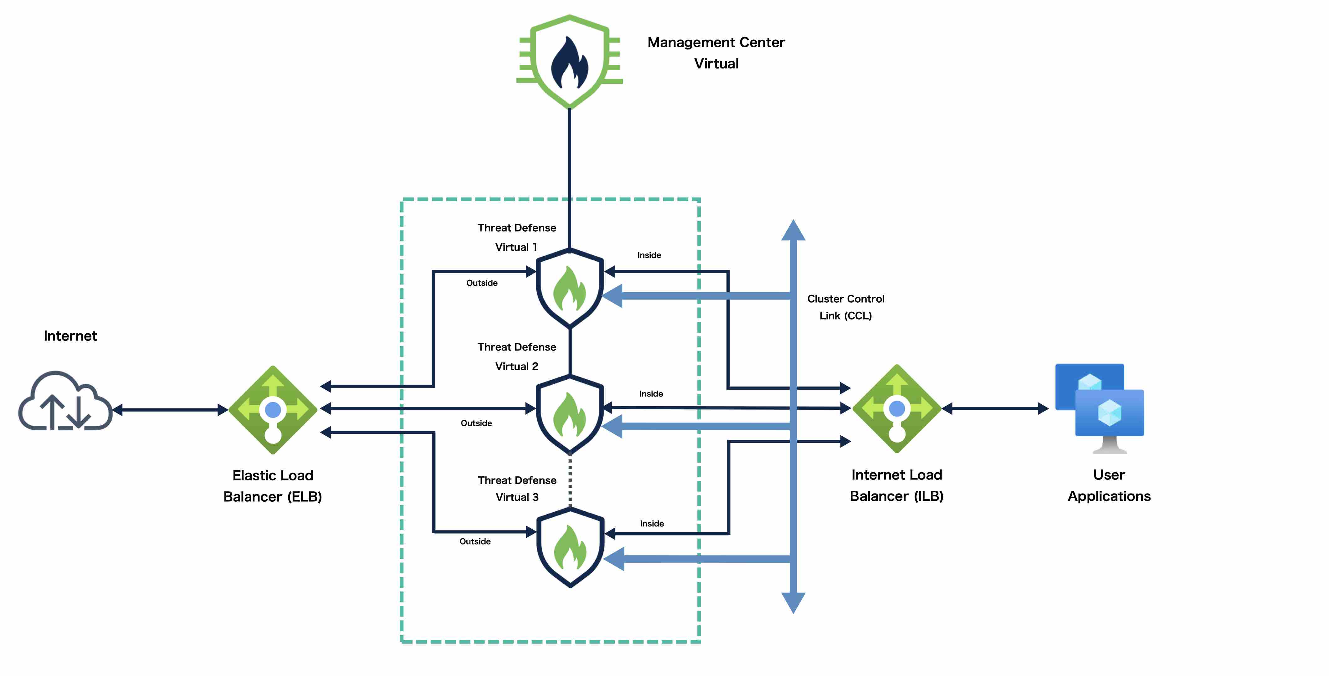
The cluster consists of multiple firewalls acting as a single device. To act as a cluster, the firewalls need the following infrastructure:
-
Isolated network for intra-cluster communication, known as the cluster control link, using VXLAN interfaces. VXLANs, which act as Layer 2 virtual networks over Layer 3 physical networks, let the Threat Defense Virtual send broadcast/multicast messages over the cluster control link.
-
Load Balancer(s)—For external load balancing, you have the following options depending on your public cloud:
-
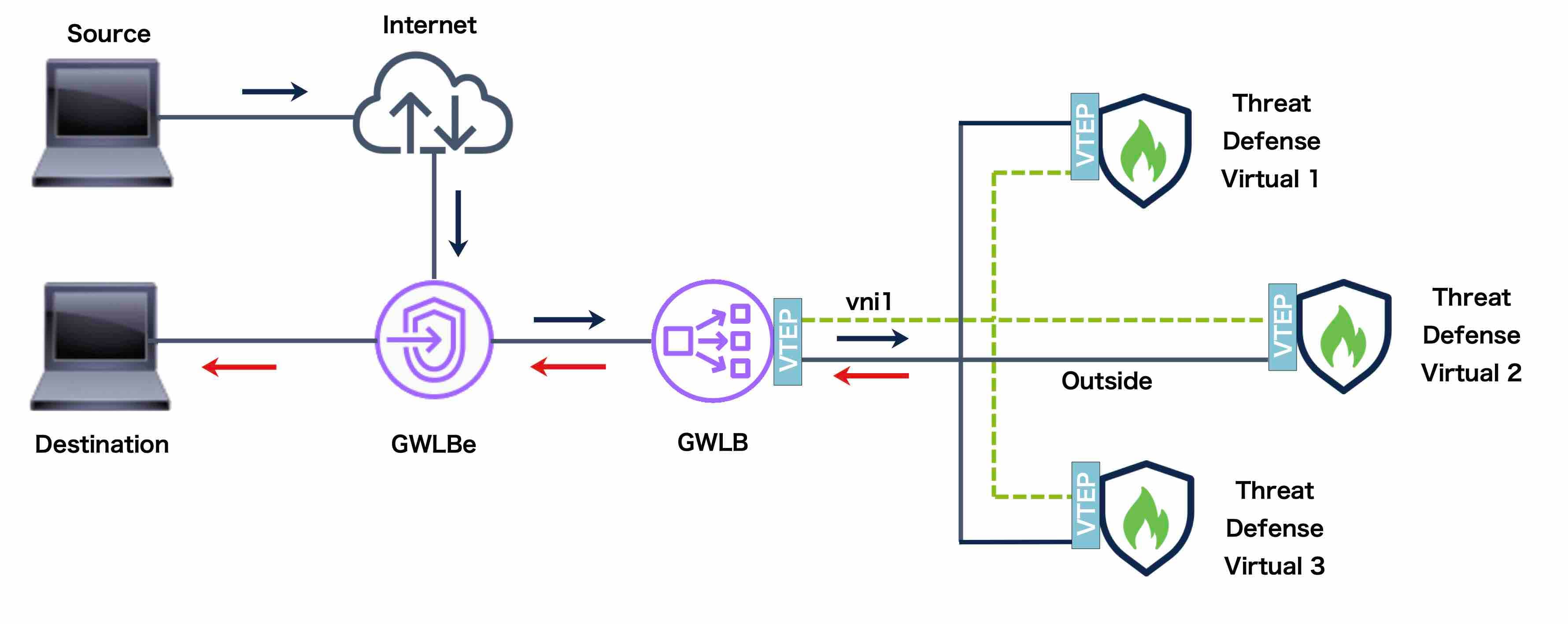
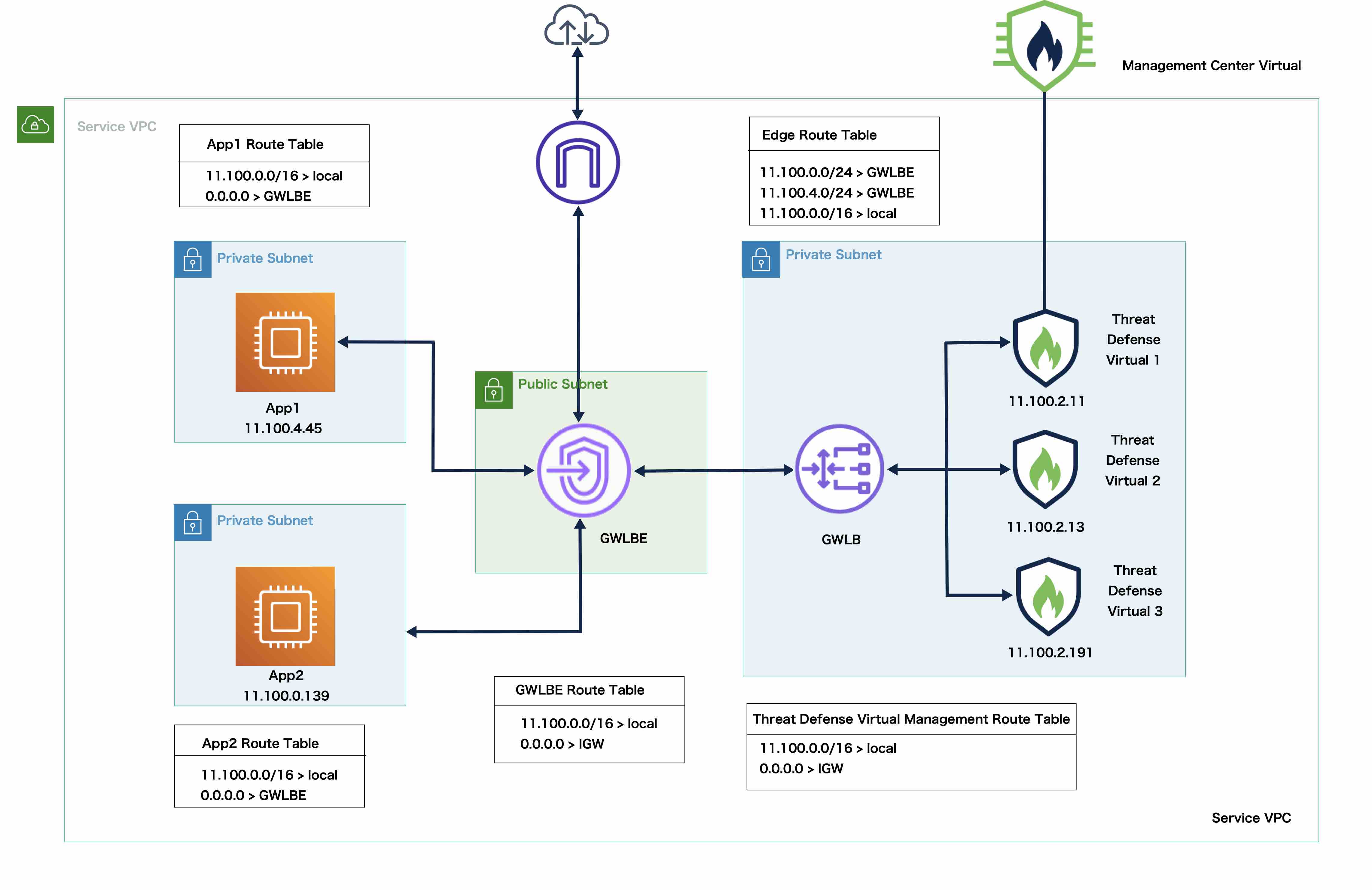
AWS Gateway Load Balancer
The AWS Gateway Load Balancer combines a transparent network gateway and a load balancer that distributes traffic and scales virtual appliances on demand. The Threat Defense Virtual supports the Gateway Load Balancer centralized control plane with a distributed data plane (Gateway Load Balancer endpoint) using a Geneve interface single-arm proxy.
-
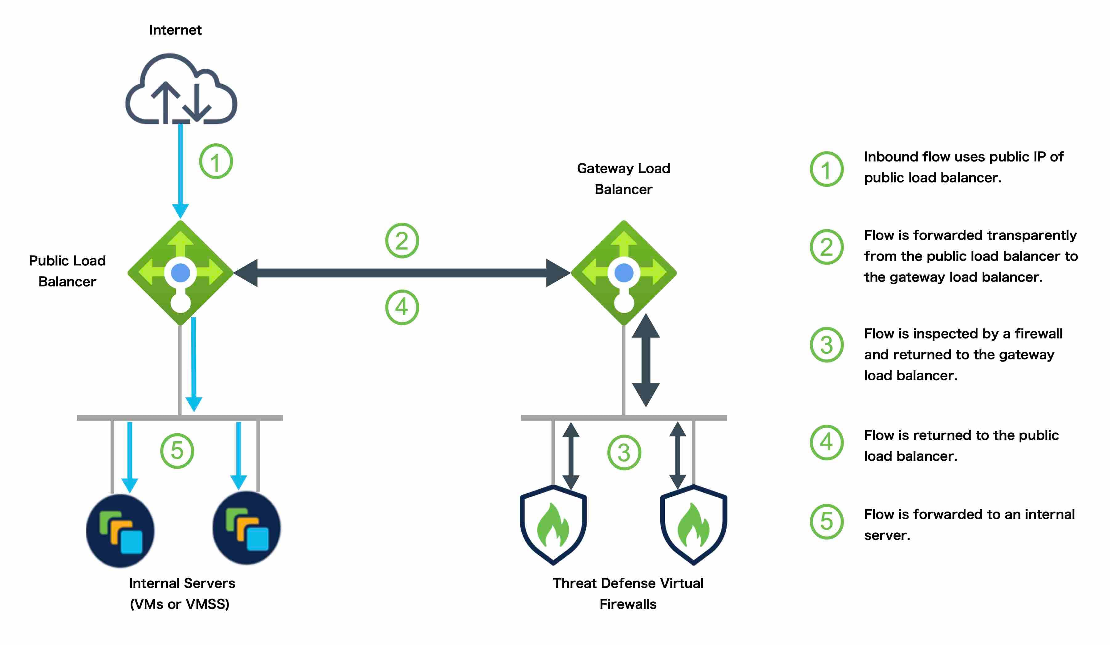
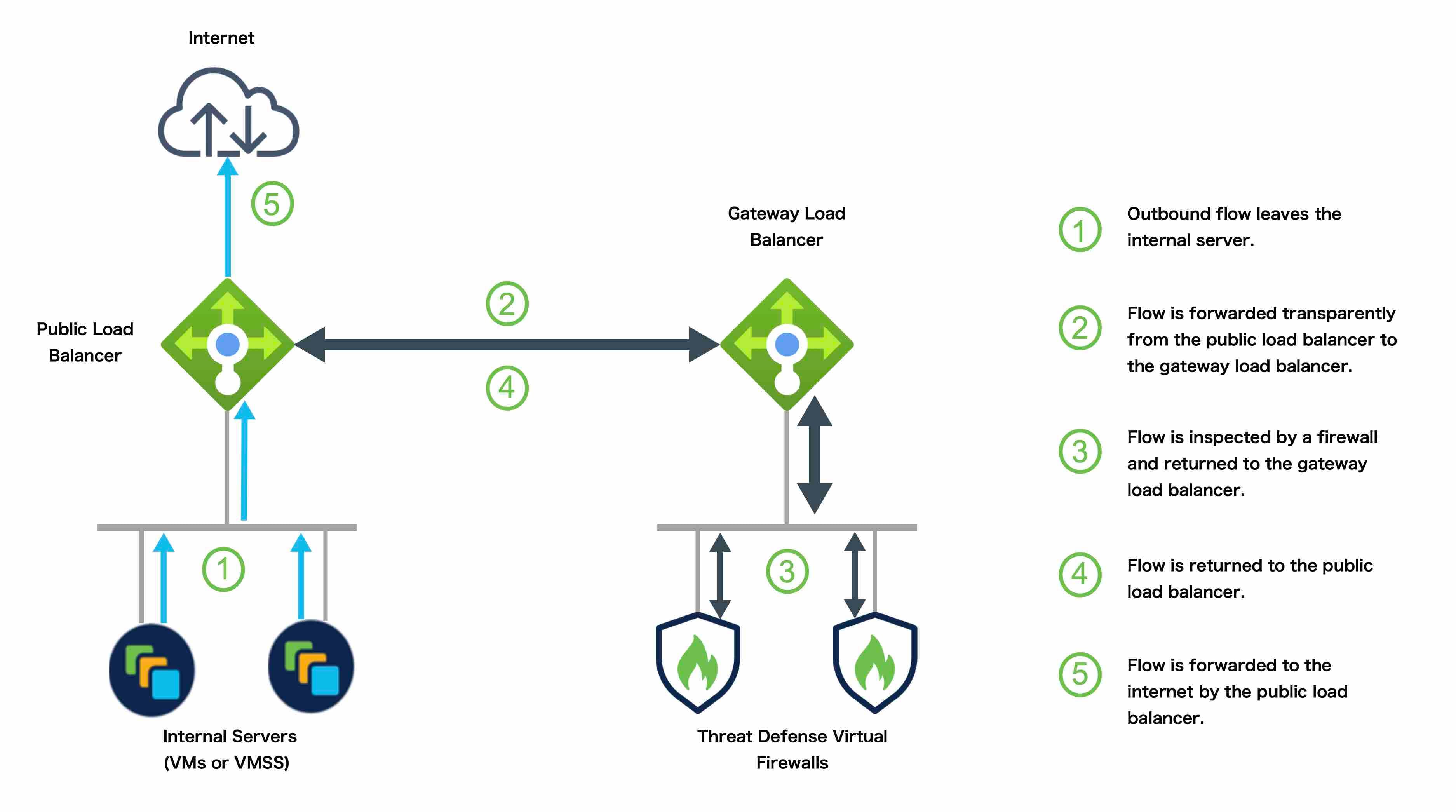
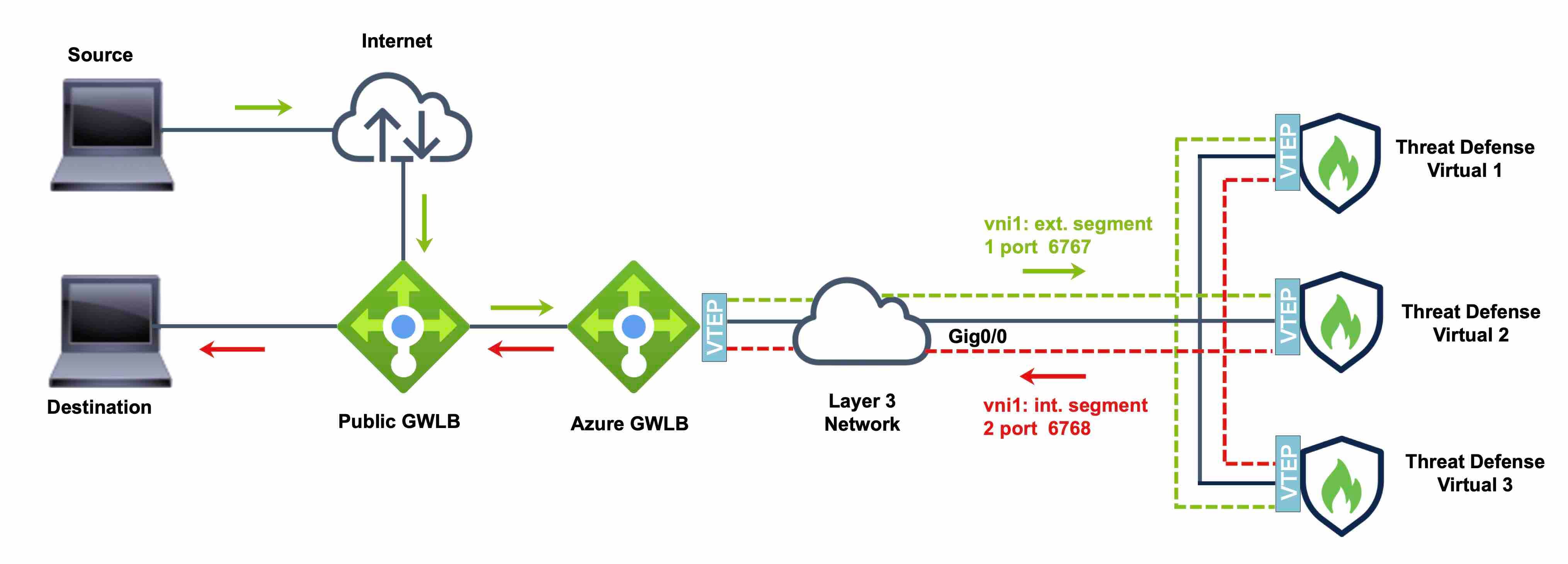
Azure Gateway Load Balancer
In an Azure service chain, Threat Defense Virtuals act as a transparent gateway that can intercept packets between the internet and the customer service. The Threat Defense Virtual defines an external interface and an internal interface on a single NIC by utilizing VXLAN segments in a paired proxy.
-
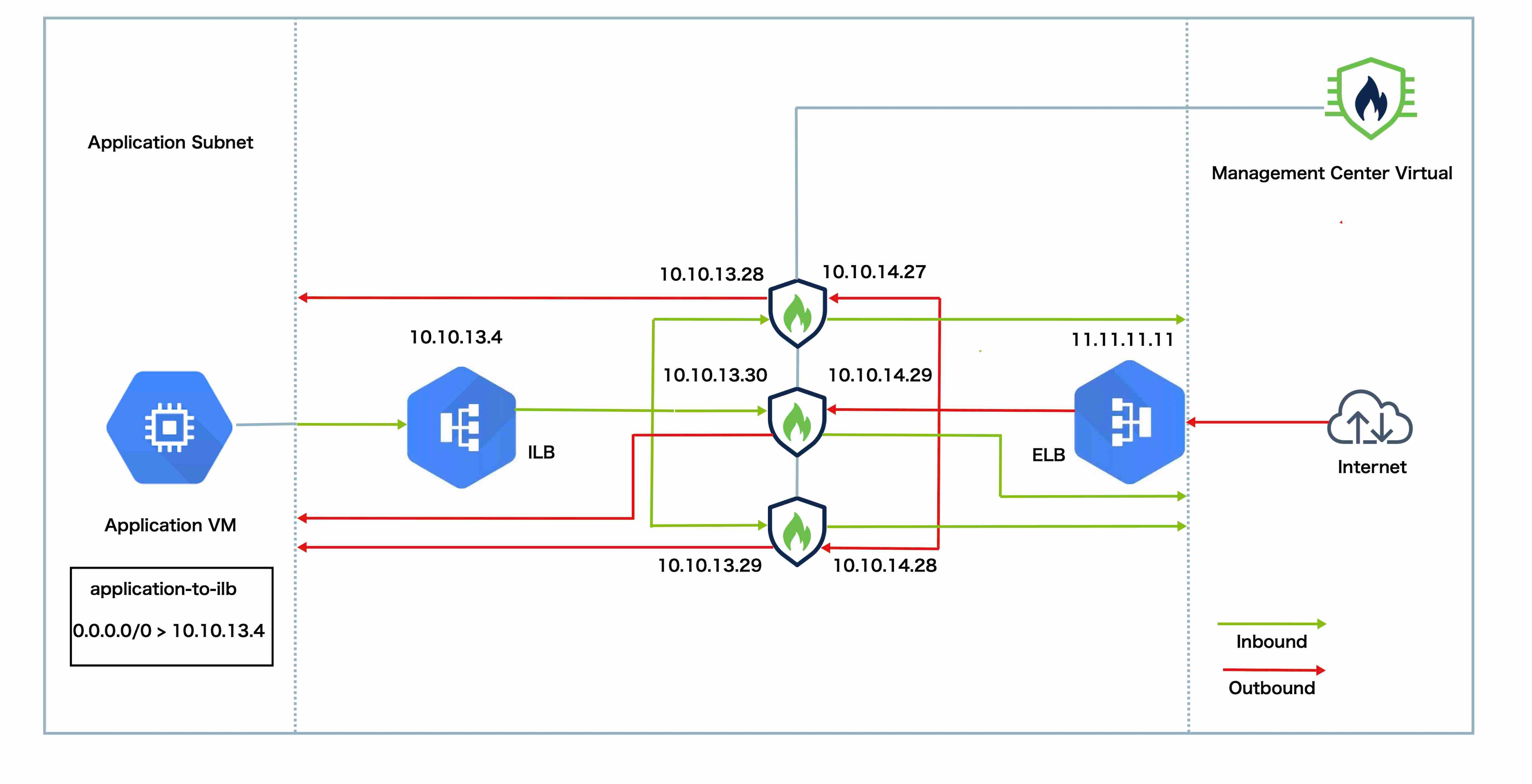
Native GCP load balancers, internal and external
-
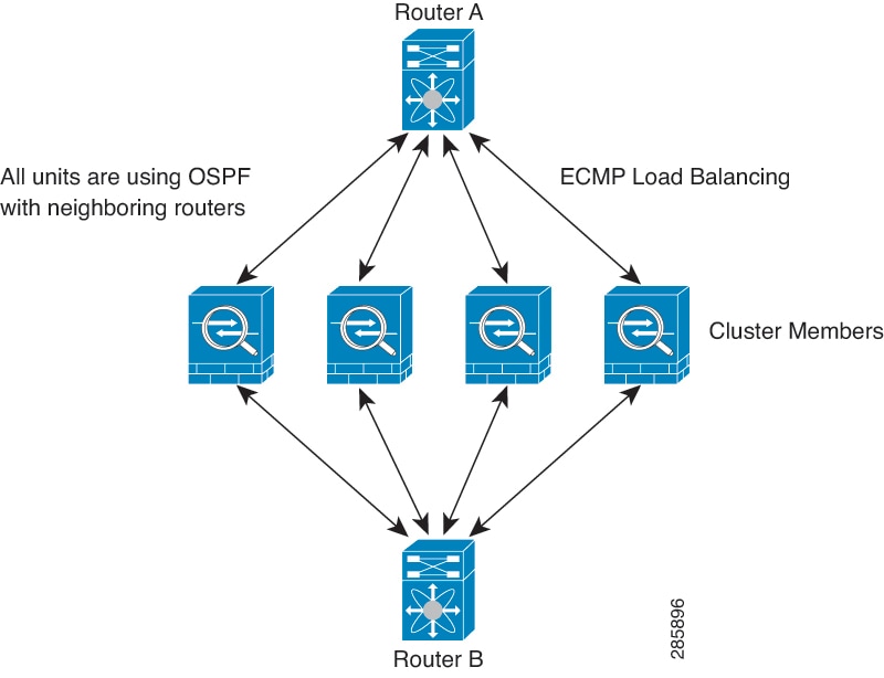
Equal-Cost Multi-Path Routing (ECMP) using inside and outside routers such as Cisco Cloud Services Router
ECMP routing can forward packets over multiple “best paths” that tie for top place in the routing metric. Like EtherChannel, a hash of source and destination IP addresses and/or source and destination ports can be used to send a packet to one of the next hops. If you use static routes for ECMP routing, then the Threat Defense failure can cause problems; the route continues to be used, and traffic to the failed Threat Defense will be lost. If you use static routes, be sure to use a static route monitoring feature such as Object Tracking. We recommend using dynamic routing protocols to add and remove routes, in which case, you must configure each Threat Defense to participate in dynamic routing.

Note
Layer 2 Spanned EtherChannels are not supported for load balancing.
-
Individual Interfaces
You can configure cluster interfaces as Individual interfaces.
Individual interfaces are normal routed interfaces, each with their own local IP address. The IP address for the interface will be configured automatically via DHCP. Static IP configuration is not supported.
Control and Data Node Roles
One member of the cluster is the control node. If multiple cluster nodes come online at the same time, the control node is determined by the priority setting; the priority is set between 1 and 100, where 1 is the highest priority. All other members are data nodes. When you first create the cluster, you specify which node you want to be the control node, and it will become the control node simply because it is the first node added to the cluster.
All nodes in the cluster share the same configuration. The node that you initially specify as the control node will overwrite the configuration on the data nodes when they join the cluster, so you only need to perform initial configuration on the control node before you form the cluster.
Some features do not scale in a cluster, and the control node handles all traffic for those features.
Cluster Control Link
Each node must dedicate one interface as a VXLAN (VTEP) interface for the cluster control link. For more information about VXLAN, see Configure VXLAN Interfaces.
VXLAN Tunnel Endpoint
VXLAN tunnel endpoint (VTEP) devices perform VXLAN encapsulation and decapsulation. Each VTEP has two interface types: one or more virtual interfaces called VXLAN Network Identifier (VNI) interfaces, and a regular interface called the VTEP source interface that tunnels the VNI interfaces between VTEPs. The VTEP source interface is attached to the transport IP network for VTEP-to-VTEP communication.
VTEP Source Interface
The VTEP source interface is a regular threat defense virtual interface with which you plan to associate the VNI interface. You can configure one VTEP source interface to act as the cluster control link. The source interface is reserved for cluster control link use only. Each VTEP source interface has an IP address on the same subnet. This subnet should be isolated from all other traffic, and should include only the cluster control link interfaces.
VNI Interface
A VNI interface is similar to a VLAN interface: it is a virtual interface that keeps network traffic separated on a given physical interface by using tagging. You can only configure one VNI interface. Each VNI interface has an IP address on the same subnet.
Peer VTEPs
Unlike regular VXLAN for data interfaces, which allows a single VTEP peer, The threat defense virtual clustering allows you to configure multiple peers.
Cluster Control Link Traffic Overview
Cluster control link traffic includes both control and data traffic.
Control traffic includes:
-
Control node election.
-
Configuration replication.
-
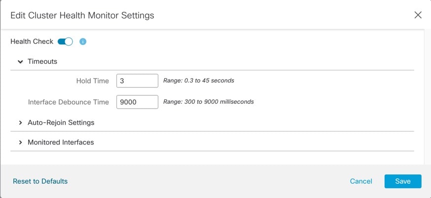
Health monitoring.
Data traffic includes:
-
State replication.
-
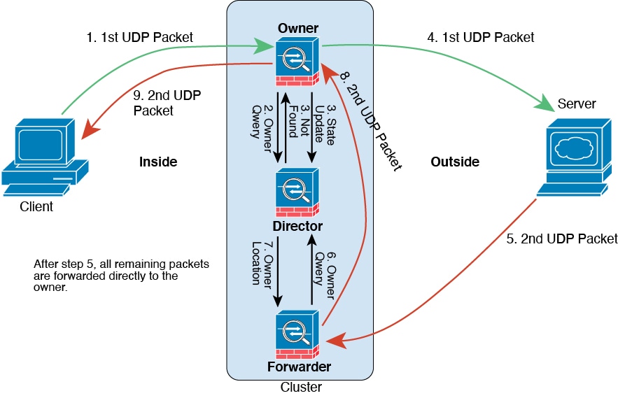
Connection ownership queries and data packet forwarding.
Configuration Replication
All nodes in the cluster share a single configuration. You can only make configuration changes on the control node (with the exception of the bootstrap configuration), and changes are automatically synced to all other nodes in the cluster.
Management Network
You must manage each node using the Management interface; management from a data interface is not supported with clustering.
















 Feedback