Static and Default Routes

This chapter describes how to configure static and default routes on the threat defense.

About Static and Default Routes

To route traffic to a non-connected host or network, you must define a route to the host or network, either using static or dynamic routing. Generally, you must configure at least one static route: a default route for all traffic that is not routed by other means to a default network gateway, typically the next hop router.

Default Route

The simplest option is to configure a default static route to send all traffic to an upstream router, relying on the router to route the traffic for you. A default route identifies the gateway IP address to which the threat defense device sends all IP packets for which it does not have a learned or static route. A default static route is simply a static route with 0.0.0.0/0 (IPv4) or ::/0 (IPv6) as the destination IP address.

You should always define a default route.

The threat defense has separate routing tables for data interfaces and for management-only interfaces (including the special Linux Management interface). You can only add a default route for the data routing table. The threat defense automatically adds a default route in the management-only routing table that sends traffic to the Linux Management interface, where a separate route lookup occurs in the Linux routing table. You can add static routes to the Linux routing table that can be used by Management using the threat defense CLI configure network static-routes command.


Note


The default Linux route is set with the configure network ipv4 or configure network ipv6 command.


Static Routes

You might want to use static routes in the following cases:

  • Your networks use an unsupported router discovery protocol.

  • Your network is small and you can easily manage static routes.

  • You do not want the traffic or CPU overhead associated with routing protocols.

  • In some cases, a default route is not enough. The default gateway might not be able to reach the destination network, so you must also configure more specific static routes. For example, if the default gateway is outside, then the default route cannot direct traffic to any inside networks that are not directly connected to the threat defense device.

  • You are using a feature that does not support dynamic routing protocols.

  • Virtual routers use static routes to create route leaks. Route leaks enable flow of traffic from an interface of a virtual router to another interface in another virtual router. For more information, see Interconnecting Virtual Routers.

Route to null0 Interface to Drop Unwanted Traffic

Access rules let you filter packets based on the information contained in their headers. A static route to the null0 interface is a complementary solution to access rules. You can use a null0 route to forward unwanted or undesirable traffic so the traffic is dropped.

Static null0 routes have a favorable performance profile. You can also use static null0 routes to prevent routing loops. BGP can leverage the static null0 route for Remotely Triggered Black Hole routing.

Route Priorities

  • Routes that identify a specific destination take precedence over the default route.

  • When multiple routes exist to the same destination (either static or dynamic), then the administrative distance for the route determines priority. Static routes are set to 1, so they typically are the highest priority routes.

  • When you have multiple static routes to the same destination with the same administrative distance, see Equal-Cost Multi-Path (ECMP) Routing.

  • For traffic emerging from a tunnel with the Tunneled option, this route overrides any other configured or learned default routes.

Transparent Firewall Mode and Bridge Group Routes

For traffic that originates on the threat defense device and is destined through a bridge group member interface for a non-directly connected network, you need to configure either a default route or static routes so the threat defense device knows out of which bridge group member interface to send traffic. Traffic that originates on the threat defense device might include communications to a syslog server or SNMP server. If you have servers that cannot all be reached through a single default route, then you must configure static routes. For transparent mode, you cannot specify the BVI as the gateway interface; only member interfaces can be used. For bridge groups in routed mode, you must specify the BVI in a static route; you cannot specify a member interface. See for more information.

Static Route Tracking

One of the problems with static routes is that there is no inherent mechanism for determining if the route is up or down. They remain in the routing table even if the next hop gateway becomes unavailable. Static routes are only removed from the routing table if the associated interface on the threat defense device goes down.

The static route tracking feature provides a method for tracking the availability of a static route and installing a backup route if the primary route should fail. For example, you can define a default route to an ISP gateway and a backup default route to a secondary ISP in case the primary ISP becomes unavailable.

The threat defense device implements static route tracking by associating a static route with a monitoring target host on the destination network that the threat defense device monitors using ICMP echo requests. If an echo reply is not received within a specified time period, the host is considered down, and the associated route is removed from the routing table. An untracked backup route with a higher metric is used in place of the removed route.

When selecting a monitoring target, you need to make sure that it can respond to ICMP echo requests. The target can be any network object that you choose, but you should consider using the following:

  • The ISP gateway (for dual ISP support) address

  • The next hop gateway address (if you are concerned about the availability of the gateway)

  • A server on the target network, such as a syslog server, that the threat defense device needs to communicate with

  • A persistent network object on the destination network


Note


A PC that may be shut down at night is not a good choice.


You can configure static route tracking for statically defined routes or default routes obtained through DHCP or PPPoE. You can only enable PPPoE clients on multiple interfaces with route tracking configured.
Requirements and Prerequisites for Static Routes

Model Support

Threat Defense

Supported Domains

Any

User Roles

Admin

Network Admin

Guidelines for Static and Default Routes

Firewall Mode and Bridge Groups

  • In transparent mode, static routes must use the bridge group member interface as the gateway; you cannot specify the BVI.

  • In routed mode, you must specify the BVI as the gateway; you cannot specify the member interface.

  • Static route tracking is not supported for bridge group member interfaces or on the BVI.

Supported Network Address

  • Static route tracking is not supported for IPv6.

  • ASA does not support CLASS E routing. Hence, CLASS E network is not routable as static routes.

Clustering and Multiple Context Mode

  • In clustering, static route tracking is only supported on the primary unit.

  • Static route tracking is not supported in multiple context mode.

Network Object Group

You cannot use a range of network objects or a network object group having a range of IP addresses while configuring a static route.

ASP and RIB Route Entries

All routes and its distance installed on the device are captured in the ASP routing table. This is common for all static and dynamic routing protocols. Only the best distance route is captured in the RIB table.

Add a Static Route

A static route defines where to send traffic for specific destination networks. You should at a minimum define a default route. A default route is simply a static route with 0.0.0.0/0 as the destination IP address.

Procedure


Step 1

Choose Devices > Device Management, and edit the threat defense device.

Step 2

Click Routing.

Step 3

(For virtual-router-aware devices) From the virtual routers drop-down list, select the virtual router for which you are configuring a static route.

Step 4

Select Static Route.

Step 5

Click Add Routes.

Step 6

Click IPv4 or IPv6 depending on the type of static route that you are adding.

Step 7

Choose the Interface to which this static route applies.

For transparent mode, choose a bridge group member interface name. For routed mode with bridge groups, you can choose either the bridge group member interface for the BVI name. To “black hole” unwanted traffic, choose the Null0 interface.

For a device using virtual routing, you can select an interface that belongs to another virtual router. You can create such a static route if you want to leak traffic from this virtual router into the other virtual router. For more information, see Interconnecting Virtual Routers.

Step 8

In the Available Network list, choose the destination network.

To define a default route, create an object with the address 0.0.0.0/0 and select it here.

Note


Though you can create and choose a Network Object Group containing a range of IP addresses, management center does not support using range of network objects while configuring a static route.

Step 9

In the Gateway or IPv6 Gateway field, enter or choose the gateway router which is the next hop for this route. You can provide an IP address or a Networks/Hosts object. When you are using static route configuration for virtual routers to leak routes, do not specify the next hop gateway.

Step 10

In the Metric field, enter the number of hops to the destination network. Valid values range from 1 to 255; the default value is 1. The metric is a measurement of the “expense” of a route, based on the number of hops (hop count) to the network on which a specific host resides. Hop count is the number of networks that a network packet must traverse, including the destination network, before it reaches its final destination. The metric is used to compare routes among different routing protocols. The default administrative distance for static routes is 1, giving it precedence over routes discovered by dynamic routing protocols but not directly connected routes. The default administrative distance for routes discovered by OSPF is 110. If a static route has the same administrative distance as a dynamic route, the static route takes precedence. Connected routes always take precedence over static or dynamically discovered routes.

Note


For a dual ISP/WAN interface configuration, you must assign same metric value for both the primary and secondary data interfaces. By default, you are not allowed to configure same metric value for two interfaces. To override validation error, ensure that the two interfaces belong to a single ECMP zone.

Step 11

(Optional) For a default route, click the Tunneled checkbox to define a separate default route for VPN traffic.

You can define a separate default route for VPN traffic if you want your VPN traffic to use a different default route than your non VPN traffic. For example, traffic incoming from VPN connections can be easily directed towards internal networks, while traffic from internal networks can be directed towards the outside. When you create a default route with the tunneled option, all traffic from a tunnel terminating on the device that cannot be routed using learned or static routes, is sent to this route. You can configure only one default tunneled gateway per device. ECMP for tunneled traffic is not supported.

Step 12

(IPv4 static route only) To monitor route availability, enter or choose the name of an SLA (service level agreement) Monitor object that defines the monitoring policy, in the Route Tracking field.

See SLA Monitor.

Note


Ensure to assign SLA for the static routes of the primary and secondary data interfaces (Dual ISP/WAN interface configuration).

Step 13

Click Ok.


Reference for Routing

This section describes underlying concepts of how routing behaves within the threat defense.

Path Determination

Routing protocols use metrics to evaluate what path will be the best for a packet to travel. A metric is a standard of measurement, such as path bandwidth, that is used by routing algorithms to determine the optimal path to a destination. To aid the process of path determination, routing algorithms initialize and maintain routing tables, which include route information. Route information varies depending on the routing algorithm used.

Routing algorithms fill routing tables with a variety of information. Destination or next hop associations tell a router that a particular destination can be reached optimally by sending the packet to a particular router representing the next hop on the way to the final destination. When a router receives an incoming packet, it checks the destination address and attempts to associate this address with a next hop.

Routing tables also can include other information, such as data about the desirability of a path. Routers compare metrics to determine optimal routes, and these metrics differ depending on the design of the routing algorithm used.

Routers communicate with one another and maintain their routing tables through the transmission of a variety of messages. The routing update message is one such message that generally consists of all or a portion of a routing table. By analyzing routing updates from all other routers, a router can build a detailed picture of network topology. A link-state advertisement, another example of a message sent between routers, informs other routers of the state of the sender links. Link information also can be used to build a complete picture of network topology to enable routers to determine optimal routes to network destinations.

Supported Route Types

There are several route types that a router can use. The threat defense device uses the following route types:

  • Static Versus Dynamic

  • Single-Path Versus Multipath

  • Flat Versus Hierarchical

  • Link-State Versus Distance Vector

Static Versus Dynamic

Static routing algorithms are actually table mappings established by the network administrator. These mappings do not change unless the network administrator alters them. Algorithms that use static routes are simple to design and work well in environments where network traffic is relatively predictable and where network design is relatively simple.

Because static routing systems cannot react to network changes, they generally are considered unsuitable for large, constantly changing networks. Most of the dominant routing algorithms are dynamic routing algorithms, which adjust to changing network circumstances by analyzing incoming routing update messages. If the message indicates that a network change has occurred, the routing software recalculates routes and sends out new routing update messages. These messages permeate the network, stimulating routers to rerun their algorithms and change their routing tables accordingly.

Dynamic routing algorithms can be supplemented with static routes where appropriate. A router of last resort (a default route for a router to which all unrouteable packets are sent), for example, can be designated to act as a repository for all unrouteable packets, ensuring that all messages are at least handled in some way.

Single-Path Versus Multipath

Some sophisticated routing protocols support multiple paths to the same destination. Unlike single-path algorithms, these multipath algorithms permit traffic multiplexing over multiple lines. The advantages of multipath algorithms are substantially better throughput and reliability, which is generally called load sharing.

Flat Versus Hierarchical

Some routing algorithms operate in a flat space, while others use routing hierarchies. In a flat routing system, the routers are peers of all others. In a hierarchical routing system, some routers form what amounts to a routing backbone. Packets from non-backbone routers travel to the backbone routers, where they are sent through the backbone until they reach the general area of the destination. At this point, they travel from the last backbone router through one or more non-backbone routers to the final destination.

Routing systems often designate logical groups of nodes, called domains, autonomous systems, or areas. In hierarchical systems, some routers in a domain can communicate with routers in other domains, while others can communicate only with routers within their domain. In very large networks, additional hierarchical levels may exist, with routers at the highest hierarchical level forming the routing backbone.

The primary advantage of hierarchical routing is that it mimics the organization of most companies and therefore supports their traffic patterns well. Most network communication occurs within small company groups (domains). Because intradomain routers need to know only about other routers within their domain, their routing algorithms can be simplified, and, depending on the routing algorithm being used, routing update traffic can be reduced accordingly.

Link-State Versus Distance Vector

Link-state algorithms (also known as shortest path first algorithms) flood routing information to all nodes in the internetwork. Each router, however, sends only the portion of the routing table that describes the state of its own links. In link-state algorithms, each router builds a picture of the entire network in its routing tables. Distance vector algorithms (also known as Bellman-Ford algorithms) call for each router to send all or some portion of its routing table, but only to its neighbors. In essence, link-state algorithms send small updates everywhere, while distance vector algorithms send larger updates only to neighboring routers. Distance vector algorithms know only about their neighbors. Typically, link-state algorithms are used in conjunction with OSPF routing protocols.

Supported Internet Protocols for Routing

The threat defense device supports several Internet protocols for routing. Each protocol is briefly described in this section.

  • Enhanced Interior Gateway Routing Protocol (EIGRP)

    EIGRP is a Cisco proprietary protocol that provides compatibility and seamless interoperation with IGRP routers. An automatic-redistribution mechanism allows IGRP routes to be imported into Enhanced IGRP, and vice versa, so it is possible to add Enhanced IGRP gradually into an existing IGRP network.

  • Open Shortest Path First (OSPF)

    OSPF is a routing protocol developed for Internet Protocol (IP) networks by the interior gateway protocol (IGP) working group of the Internet Engineering Task Force (IETF). OSPF uses a link-state algorithm to build and calculate the shortest path to all known destinations. Each router in an OSPF area includes an identical link-state database, which is a list of each of the router usable interfaces and reachable neighbors.

  • Routing Information Protocol (RIP)

    RIP is a distance-vector protocol that uses hop count as its metric. RIP is widely used for routing traffic in the global Internet and is an interior gateway protocol (IGP), which means that it performs routing within a single autonomous system.

  • Border Gateway Protocol (BGP)

    BGP is an interautonomous system routing protocol. BGP is used to exchange routing information for the Internet and is the protocol used between Internet service providers (ISP). Customers connect to ISPs, and ISPs use BGP to exchange customer and ISP routes. When BGP is used between autonomous systems (AS), the protocol is referred to as External BGP (EBGP). If a service provider is using BGP to exchange routes within an AS, then the protocol is referred to as Interior BGP (IBGP).

Routing Table

The threat defense uses separate routing tables for data traffic (through-the-device) and for management traffic (from-the-device). This section describes how the routing tables work. For information about the management routing table, see also Routing Table for Management Traffic.

How the Routing Table Is Populated

The threat defense routing table can be populated by statically defined routes, directly connected routes, and routes discovered by the dynamic routing protocols. Because the threat defense device can run multiple routing protocols in addition to having static and connected routes in the routing table, it is possible that the same route is discovered or entered in more than one manner. When two routes to the same destination are put into the routing table, the one that remains in the routing table is determined as follows:

  • If the two routes have different network prefix lengths (network masks), then both routes are considered unique and are entered into the routing table. The packet forwarding logic then determines which of the two to use.

    For example, if the RIP and OSPF processes discovered the following routes:

    • RIP: 192.168.32.0/24

    • OSPF: 192.168.32.0/19

    Even though OSPF routes have the better administrative distance, both routes are installed in the routing table because each of these routes has a different prefix length (subnet mask). They are considered different destinations and the packet forwarding logic determines which route to use.

  • If the threat defense device learns about multiple paths to the same destination from a single routing protocol, such as RIP, the route with the better metric (as determined by the routing protocol) is entered into the routing table.

    Metrics are values associated with specific routes, ranking them from most preferred to least preferred. The parameters used to determine the metrics differ for different routing protocols. The path with the lowest metric is selected as the optimal path and installed in the routing table. If there are multiple paths to the same destination with equal metrics, load balancing is done on these equal cost paths.

  • If the threat defense device learns about a destination from more than one routing protocol, the administrative distances of the routes are compared, and the routes with lower administrative distance are entered into the routing table.

Administrative Distances for Routes

You can change the administrative distances for routes discovered by or redistributed into a routing protocol. If two routes from two different routing protocols have the same administrative distance, then the route with the lower default administrative distance is entered into the routing table. In the case of EIGRP and OSPF routes, if the EIGRP route and the OSPF route have the same administrative distance, then the EIGRP route is chosen by default.

Administrative distance is a route parameter that the threat defense device uses to select the best path when there are two or more different routes to the same destination from two different routing protocols. Because the routing protocols have metrics based on algorithms that are different from the other protocols, it is not always possible to determine the best path for two routes to the same destination that were generated by different routing protocols.

Each routing protocol is prioritized using an administrative distance value. The following table shows the default administrative distance values for the routing protocols supported by the threat defense device.

Table 1. Default Administrative Distance for Supported Routing Protocols

Route Source

Default Administrative Distance

Connected interface

0

VPN route

1

Static route

1

EIGRP Summary Route

5

External BGP

20

Internal EIGRP

90

OSPF

110

IS-IS

115

RIP

120

EIGRP external route

170

Internal and local BGP

200

Unknown

255

The smaller the administrative distance value, the more preference is given to the protocol. For example, if the threat defense device receives a route to a certain network from both an OSPF routing process (default administrative distance - 110) and a RIP routing process (default administrative distance - 120), the threat defense device chooses the OSPF route because OSPF has a higher preference. In this case, the router adds the OSPF version of the route to the routing table.

A VPN advertised route (V-Route/RRI)) is equivalent to a static route with the default administrative distance 1. But it has a higher preference as with the network mask 255.255.255.255.

In this example, if the source of the OSPF-derived route was lost (for example, due to a power shutdown), the threat defense device would then use the RIP-derived route until the OSPF-derived route reappears.

The administrative distance is a local setting. For example, if you change the administrative distance of routes obtained through OSPF, that change would only affect the routing table for the threat defense device on which the command was entered. The administrative distance is not advertised in routing updates.

Administrative distance does not affect the routing process. The routing processes only advertise the routes that have been discovered by the routing process or redistributed into the routing process. For example, the RIP routing process advertises RIP routes, even if routes discovered by the OSPF routing process are used in the routing table.

Backup Dynamic and Floating Static Routes

A backup route is registered when the initial attempt to install the route in the routing table fails because another route was installed instead. If the route that was installed in the routing table fails, the routing table maintenance process calls each routing protocol process that has registered a backup route and requests them to reinstall the route in the routing table. If there are multiple protocols with registered backup routes for the failed route, the preferred route is chosen based on administrative distance.

Because of this process, you can create floating static routes that are installed in the routing table when the route discovered by a dynamic routing protocol fails. A floating static route is simply a static route configured with a greater administrative distance than the dynamic routing protocols running on the threat defense device. When the corresponding route discovered by a dynamic routing process fails, the static route is installed in the routing table.

How Forwarding Decisions Are Made

Forwarding decisions are made as follows:

  • If the destination does not match an entry in the routing table, the packet is forwarded through the interface specified for the default route. If a default route has not been configured, the packet is discarded.

  • If the destination matches a single entry in the routing table, the packet is forwarded through the interface associated with that route.

  • If the destination matches more than one entry in the routing table, then the packet is forwarded out of the interface associated with the route that has the longer network prefix length.

For example, a packet destined for 192.168.32.1 arrives on an interface with the following routes in the routing table:

  • 192.168.32.0/24 gateway 10.1.1.2

  • 192.168.32.0/19 gateway 10.1.1.3

In this case, a packet destined to 192.168.32.1 is directed toward 10.1.1.2, because 192.168.32.1 falls within the 192.168.32.0/24 network. It also falls within the other route in the routing table, but 192.168.32.0/24 has the longest prefix within the routing table (24 bits verses 19 bits). Longer prefixes are always preferred over shorter ones when forwarding a packet.


Note


Existing connections continue to use their established interfaces even if a new similar connection would result in different behavior due to a change in routes.


Dynamic Routing and High Availability

Dynamic routes are synchronized on the standby unit when the routing table changes on the active unit. This means that all additions, deletions, or changes on the active unit are immediately propagated to the standby unit. If the standby unit becomes active in an active/standby ready High Availability pair, it will already have an identical routing table as that of the former active unit because routes are synchronized as a part of the High Availability bulk synchronization and continuous replication processes.

Dynamic Routing in Clustering

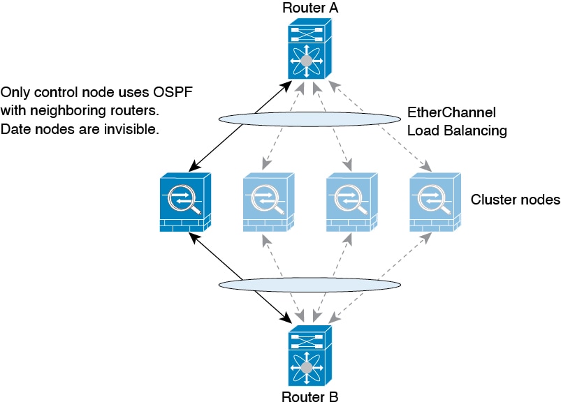
The routing process only runs on the control node, and routes are learned through the control node and replicated to data nodes. If a routing packet arrives at a data node, it is redirected to the control node.

Figure 1. Dynamic Routing in Spanned EtherChannel Mode

After the data node learn the routes from the control node, each node makes forwarding decisions independently.

The OSPF LSA database is not synchronized from the control node to data nodes. If there is a control node switchover, the neighboring router will detect a restart; the switchover is not transparent. The OSPF process picks an IP address as its router ID. Although not required, you can assign a static router ID to ensure a consistent router ID is used across the cluster. See the OSPF Non-Stop Forwarding feature to address the interruption.

Dynamic Routing in Individual Interface Mode

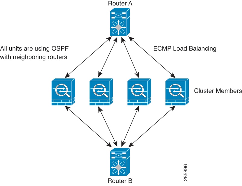
In Individual interface mode, each node runs the routing protocol as a standalone router, and routes are learned by each node independently.

Figure 2. Dynamic Routing in Individual Interface Mode

In the above diagram, Router A learns that there are 4 equal-cost paths to Router B, each through a node. ECMP is used to load balance traffic between the 4 paths. Each node picks a different router ID when talking to external routers.

You must configure a cluster pool for the router ID so that each node has a separate router ID.

EIGRP does not form neighbor relationships with cluster peers in individual interface mode.


Note


If the cluster has multiple adjacencies to the same router for redundancy purposes, asymmetric routing can lead to unacceptable traffic loss. To avoid asymmetric routing, group all of these node interfaces into the same traffic zone. See Create an ECMP Zone.


Routing Table for Management Traffic

The threat defense device includes the following routing tables for from-the-device management traffic:

  • Linux Management routing table—Special management traffic sourced from the Management interface such as management center communication,the licensing communication, and database updates always uses the Linux Management routing table.

  • Data routing table—All from-the-device traffic (as well as all through traffic) uses the data routing table by default. All regular data interfaces are part of this routing table. Most services let you choose a specific interface, so only routes associated with that interface are used.

  • Management-only routing table—The Management interface and all data interfaces that you set to management-only are part of this routing table. To send from-the-device traffic from any of these interfaces, you must choose a specific management-only interface when you configure the service. An exception is for DNS lookups: in some cases, threat defense will use data and then fall back to management automatically if a route is not found. You can add static routes for management-only interfaces, but not for the special Management interface. The threat defense device automatically adds a default route for Management that forwards traffic to Linux, where a separate route lookup occurs in the Linux routing table. You can add static routes to the Linux routing table that can be used by Management using the threat defense CLI configure network static-routes command.


    Note


    The default Linux route is set with the configure network ipv4 or configure network ipv6 command.


Note


For devices that have not yet merged the Management and legacy Diagnostic interfaces, see refer to pre-7.3 versions of this guide.


Equal-Cost Multi-Path (ECMP) Routing

The threat defense device supports Equal-Cost Multi-Path (ECMP) routing.

You can have up to 8 equal cost static or dynamic routes per interface. For example, you can configure multiple default routes on the outside interface that specify different gateways.


route for 0.0.0.0 0.0.0.0 through outside to 10.1.1.2
route for 0.0.0.0 0.0.0.0 through outside to 10.1.1.3
route for 0.0.0.0 0.0.0.0 through outside to 10.1.1.4

In this case, traffic is load-balanced on the outside interface between 10.1.1.2, 10.1.1.3, and 10.1.1.4. Traffic is distributed among the specified gateways based on an algorithm that hashes the source and destination IP addresses, incoming interface, protocol, source and destination ports.

ECMP Across Multiple Interfaces Using Traffic Zones

If you configure traffic zones to contain a group of interfaces, you can have up to 8 equal cost static or dynamic routes across up to 8 interfaces within each zone. For example, you can configure multiple default routes across three interfaces in the zone:


route for 0.0.0.0 0.0.0.0 through outside1 to 10.1.1.2
route for 0.0.0.0 0.0.0.0 through outside2 to 10.2.1.2
route for 0.0.0.0 0.0.0.0 through outside3 to 10.3.1.2

Similarly, your dynamic routing protocol can automatically configure equal cost routes. The threat defense device load-balances traffic across the interfaces with a more robust load balancing mechanism.

When a route is lost, the device seamlessly moves the flow to a different route.

About Route Maps

Route maps are used when redistributing routes into an OSPF, RIP, EIGRP or BGP routing process. They are also used when generating a default route into an OSPF routing process. A route map defines which of the routes from the specified routing protocol are allowed to be redistributed into the target routing process.

Route maps have many features in common with widely known ACLs. These are some of the traits common to both:

  • They are an ordered sequence of individual statements, and each has a permit or deny result. Evaluation of an ACL or a route map consists of a list scan, in a predetermined order, and an evaluation of the criteria of each statement that matches. A list scan is aborted once the first statement match is found and an action associated with the statement match is performed.

  • They are generic mechanisms. Criteria matches and match interpretation are dictated by the way that they are applied and the feature that uses them. The same route map applied to different features might be interpreted differently.

These are some of the differences between route maps and ACLs:

  • Route maps are more flexible than ACLs and can verify routes based on criteria which ACLs can not verify. For example, a route map can verify if the type of route is internal.

  • Each ACL ends with an implicit deny statement, by design convention. If the end of a route map is reached during matching attempts, the result depends on the specific application of the route map. Route maps that are applied to redistribution behave the same way as ACLs: if the route does not match any clause in a route map then the route redistribution is denied, as if the route map contained a deny statement at the end.

Permit and Deny Clauses

Route maps can have permit and deny clauses. The deny clause rejects route matches from redistribution. You can use an ACL as the matching criterion in the route map. Because ACLs also have permit and deny clauses, the following rules apply when a packet matches the ACL:

  • ACL permit + route map permit: routes are redistributed.

  • ACL permit + route map deny: routes are not redistributed.

  • ACL deny + route map permit or deny: the route map clause is not matched, and the next route-map clause is evaluated.

Match and Set Clause Values

Each route map clause has two types of values:

  • A match value selects routes to which this clause should be applied.

  • A set value modifies information that will be redistributed into the target protocol.

For each route that is being redistributed, the router first evaluates the match criteria of a clause in the route map. If the match criteria succeeds, then the route is redistributed or rejected as dictated by the permit or deny clause, and some of its attributes might be modified by the values set from the set commands. If the match criteria fail, then this clause is not applicable to the route, and the software proceeds to evaluate the route against the next clause in the route map. Scanning of the route map continues until a clause is found that matches the route or until the end of the route map is reached.

A match or set value in each clause can be missed or repeated several times, if one of these conditions exists:

  • If several match entries are present in a clause, all must succeed for a given route in order for that route to match the clause (in other words, the logical AND algorithm is applied for multiple match commands).

  • If a match entry refers to several objects in one entry, either of them should match (the logical OR algorithm is applied).

  • If a match entry is not present, all routes match the clause.

  • If a set entry is not present in a route map permit clause, then the route is redistributed without modification of its current attributes.


Note


Do not configure a set entry in a route map deny clause because the deny clause prohibits route redistribution—there is no information to modify.


A route map clause without a match or set entry does perform an action. An empty permit clause allows a redistribution of the remaining routes without modification. An empty deny clause does not allow a redistribution of other routes (this is the default action if a route map is completely scanned, but no explicit match is found).