Network-initiated Messages Support

Feature Summary and Revision History

Summary Data

Table 1. Summary Data
Applicable Product(s) or Functional Area SMF
Applicable Platform(s) SMI
Feature Default Setting Enabled – Always-on
Related Changes in this Release Not Applicable
Related Documentation Not Applicable

Revision History

Table 2. Revision History
Revision Details Release
First introduced. Pre-2020.02.0

Feature Description

Connection Management (CM) includes the functions to establish and release a NAS signaling connection between a UE and the Access and Mobility Management Function (AMF) over the N1 interface. This signaling connection enables the NAS signaling exchange between the UE and the core network.

The 5GS CM states determine the NAS signaling connection of the UE with the AMF. The following are the CM states:

  • CM-Idle—When a UE is in the CM-Idle state, the UE has no NAS signaling connection established with the AMF over the N1 interface. The AN signaling connection, N2 connection, and N3 connection do not exist in this state.

  • CM-Connected—When a UE is in the CM-Connected state, the UE has a NAS signaling connection with the AMF over the N1 interface. A NAS signaling connection uses an RRC Connection between the UE and the NG-RAN and an NGAP UE association between the AN and the AMF for the 3GPP access.

The CM states for the 3GPP access and the non-3GPP access are independent of each other. It implies that both the access can be in the CM-Idle state and the CM-Connected state simultaneously.

SMF supports network-initiated messages when a UE is either in the CM-Idle state or in the CM-Connected state.

How it Works

When connected to the 5G core, a UE can be in CM-Connected with RRC Inactive state too. This state is between the CM-Idle and CM-Connected states.

The SMF cannot identify the UE CM state when the state is between UE and AMF. The SMF only identifies the user plane connection state. This state and the N1 and N2 transfer message response status control the behavior of SMF for network-initiated messages. These messages are for signaling modification or downlink data-related user plane activation procedures. The details for these procedures are described in the following call flows.

Call Flows

This section describes the following call flows:

  • Downlink Data Notification User Plane Activation Call Flow for UE in CM-Connected State

  • Downlink Data Notification User Plane Activation Call Flow for UE in CM-Idle State

  • Network-Initiated Modification Call Flow for Active User Plane and UE in CM-Connected State

  • Network-initiated Modification Call Flow for Inactive User Plane and UE in CM-Idle State

  • Network-initiated Modification Call Flow for Inactive User Plane and UE in CM-Connected State

Downlink Data Notification User Plane Activation Call Flow for UE in CM-Connected State

This section describes the downlink data notification User Plane activation call flow when UE is in the CM-Connected state.

Figure 1. Downlink Data Notification User Plane Activation Call Flow for UE in CM-Connected State
Table 3. Downlink Data Notification User Plane Activation Call Flow Description for UE in CM-Connected State
Step Description
1 When the UPF receives the downlink data for a PDU session and if no AN tunnel information is saved in the UPF for the PDU session, the UPF buffers the downlink data. The buffering is done based on the instruction from the SMF.
2 The UPF sends data notification towards SMF. This notification includes the N4 session ID, the information to identify the QoS flow for the DL data packet, and the DSCP details.
3 The SMF sends the acknowledgement data notification to the UPF.
4 The SMF initiates the NAMF communication N1 and N2 message transfer towards the AMF. This message transfer includes details, such as PDU session ID, N2 SM information (QFIs, QoS profiles), CN N3 tunnel information, S-NSSAI, ARP, Paging Policy Indicator, 5QI, N1 and N2 transfer failure notification target address, and the PDU session resource setup request IE.
5 As the UE is in CM-Connected state, the AMF initiates N1 and N2 transfer response. This response includes the “200 OK” status code and the “N1_N2_TRANSFER_INITIATED” cause.
6 The User Plane Reactivation procedures begin. The reactivation procedures set up the radio resources and activate the user plane to establish the N3 tunnel.
7 The AMF sends the NSMF PDU Session Update SM Context Request toward SMF. This request contains the SM information of the N2 interface. The connection state of user plane is activated.
8 The SMF sends the N4 modification procedure toward the UPF to activate the session and to update the AN tunnel information, which is the IP and TEID. The session is activated by performing the remove buffer action and the set forward action.
9 The UPF modifies the session and sends the acknowledgement of the modification to the SMF.
10 The SMF responds back to the AMF with “200 OK” status code for NSMF PDU Session Update SM Context Request with the connection state of user plane as activated.

Note

The following N1 and N2 response error cases are handled:


  • For 404 Context Not Found status, a PDU session is released.

  • For 504 or 403 status with the "UE_IN_NON_ALLOWED_AREA" and "NOT_REACHABLE" cause, an N4 modification request is sent to drop the buffered packets and to not send the CP notification for the downlink data.

  • For the N1and N2 transfer notification failure, the N4 modification request is sent to drop the buffered packets and to not send the CP notification for downlink data.

  • For 409 status code with the Retry After timer value, the N1 and N2 transfer is re-initiated after the timeout value.

  • For the 409 status code with "HIGHER_PRIORITY_REQUEST_ONGOING" cause, the lower priority N1 and N2 transfers are not allowed. Only the higher priority transfers are communicated to the AMF.

Downlink Data Notification User Plane Activation Call Flow for UE in CM-Idle State

This section describes the downlink data notification User Plane activation call flow when UE is in CM-Idle state.

Figure 2. Downlink Data Notification User Plane Activation Call Flow for UE in CM-Idle State
Table 4. Downlink Data Notification User Plane Activation Call Flow Description for UE in CM-Idle State
Step Description
1 When the UPF receives the downlink data for a PDU session and if no AN tunnel information is saved in the UPF for the PDU session, then based on the instruction from the SMF, the UPF buffers the downlink data.
2 The UPF sends data notification towards the SMF. This notification includes the N4 Session ID, the information to identify the QoS flow for the DL data packet, and the DSCP details.
3 The SMF sends the acknowledgement data notification to the UPF.
4 The SMF initiates the NAMF communication N1 and N2 message transfer toward AMF. This message transfer includes details, such as PDU session ID, N2 SM information (QFIs, QoS profiles), CN N3 tunnel information, S-NSSAI, ARP, Paging Policy Indicator, 5QI, and N1 and N2 transfer failure notification target address.
5 As the UE is in CM-Connected state, the AMF initiates N1 and N2 transfer response. This response includes the “202 Accepted” status code and “ATTEMPTING_TO_REACH_UE” cause.
6 The AMF triggers the paging procedure towards the UE.
7 The UE receives the paging request and initiates the requested service to activate the session.
8 The AMF initiates the NSMF PDU Session Update SM Context Request towards SMF with connection state of user plane configured as activating.
9 The SMF responds back to the AMF with “200 OK” status code for the NSMF PDU Session Update SM Context Request. This request includes details, such as N2 SM information (QFIs, QoS profiles), CN N3 tunnel information, S-NSSAI, ARP, Paging Policy Indicator, 5QI, N1 and N2 transfer failure notification target address, and the PDU session resource setup request IE.
10 The AMF sends the NSMF PDU Session Update SM Context Request towards the SMF. This request contains the SM information of the N2 interface. The connection state of user plane is Activating.
11 The SMF initiates the N4 modification procedure towards the UPF to activate the session and to update the AN tunnel information, which is the IP and TEID. The session is activated by performing the remove buffer action and set forward action.
12 The UPF modifies the session and sends the acknowledgement of the modification to the SMF.
13 The SMF responds back to the AMF with “200 OK” status code for NSMF PDU Session Update SM Context Request with connection state of user plane as Activated.

Network-Initiated Modification Call Flow for Active User Plane and UE in CM-Connected State

This section describes the network-initiated modification call flow when the UE is in CM-Connected State and the User Plane is activated. The network can be PCF, UDM, or SMF.

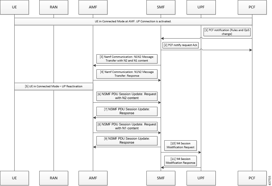
Figure 3. Network-Initiated Modification Call Flow for UE in CM-Connected State and Activated User Plane
Table 5. Network-Initiated Modification Call Flow Description for UE in CM-Connected State and Activated User Plane
Step Description
1 The PCF sends the notification towards SMF with policy decision to apply.
2 The SMF sends an acknowledgement for the policy notification to the PCF.
3 The SMF identifies the changes in QoS model that occur due to policy decision and triggers the NAMF Communication N1 and N2 message transfer toward AMF. This message transfer includes details, such as PDU Session ID, N2 SM information, N1 SM information, and N1 and N2 transfer failure notification target address. N2 includes the PDU session resource modify request transfer IE and N1 includes the PDU session modification request.
4 As UE is in CM-Connected state, the AMF initiates N1 and N2 transfer response. This response includes the “200 OK” status code and “N1_N2_TRANSFER_INITIATED” cause.
5 The user plane modification procedures begin both towards RAN and UE.
6 After receiving a response from RAN, the AMF sends the NSMF PDU Session Update SM Context Request towards the SMF. This request contains the SM information of the N2 interface.
7 The SMF responds back to the AMF with “200 OK” status code for the NSMF PDU Session Update SM Context Request.
8 After receiving a response from the UE, the AMF sends the NSMF PDU Session Update SM Context Request toward SMF. This request contains the SM information of the N1 interface.
9 The SMF responds back to the AMF with “200 OK” status code for NSMF PDU Session Update SM Context Request.
10 Based on the new QoS information, the SMF initiates the N4 Modification procedure towards the UPF to modify the session.
11 The UPF modifies the session and sends the acknowledgement of modification to the SMF.

Network-initiated Modification Call Flow for Inactive User Plane and UE in CM-Connected State

This section describes the network-initiated modification procedure when the UE is in CM-Connected state and the User Plane (UP) context is deactivated.

  1. The PCF sends a policy update notification to the SMF for a PDU session with rules and QoS change. The SMF handles the updated policy rules when received in a notification from the PCF.

  2. The SMF returns the “200 OK” status code to the PCF.

  3. The SMF sends only N1 message PDU Session Modification Command to the UE with the modified rules and QoS change, using the NAMF Communication N1 N2 Message Transfer service operation towards the AMF.

  4. The AMF sends the NAMF Communication N1 N2 Message Transfer response to the SMF. This response includes the “200 OK” status code and the “N1N2_TRANSFER_INITIATED” cause.

  5. The SMF waits for the Nsmf_PDUSession_UpdateSMContext message from the AMF.

  6. After receiving the response from UE, the SMF updates the subscriber’s session in the UPF with the modified parameter values and the UP context state remains as deactivated.

  7. The SMF sends N4 Session Modification request to the UPF updating the User Plane tunnel modified rules and the QoS details.

  8. The UPF sends the N4 Session Modification response for the PDU session.

  9. The SMF activates the UP connection as a result of the trigger to send downlink or uplink data.

Network-initiated Modification Call Flow for Inactive User Plane and UE in CM-Idle State

This section describes the network-initiated modification procedure when the UE is in CM-Idle state and the User Plane (UP) context is deactivated.

The SMF supports the following use cases during the network-initiated PDU session modification procedure:

  • When the UE turns active with the service request for PDN activation

  • When the UE turns active with the control service request

Use case 1: When the UE turns active with the service request for PDN activation

  1. The PCF sends a policy update notification to the SMF for a PDU session with rules and QoS change. The SMF handles the updated policy rules when received in a notification from the PCF.

  2. The SMF returns the “200 OK” status code to the PCF.

  3. The SMF sends only N1 message PDU Session Modification Command to the UE with the modified rules and QoS change, using the NAMF Communication N1 N2 Message Transfer service operation towards the AMF.

  4. The AMF sends the NAMF Communication N1 N2 Message Transfer response to the SMF. This response includes the “200 OK” status code and the “ATTEMPTING_TO_REACH_UE” cause.

  5. The SMF stops the retransmission of the N1 - PDU Session Modification response message to the UE. Further, it stops the N1 PDU Modification Command retransmission timer and waits for a response from the UE.

  6. The UE receives the paging request from the AMF and initiates the requested service to activate the PDU session. The UE includes the PDU Session ID in PDU Session-to-Activate list only if the UP context needs to be activated.

    The SMF initiates the Idle-to-Active PDU Session transition procedure and suspends the current modification procedure.

  7. After the Idle-to-Active procedure is complete, the SMF restarts the modification procedure and sends both the N1 and N2 content in N1 N2 transfer message and waits for both N1 and N2 response from the UE and gNB respectively.

  8. The SMF receives the N2 response from gNB, and the N1 response from the UE respectively.

  9. The SMF sends N4 Session Modification request to the UPF updating the User Plane tunnel modified rules and the QoS details.

  10. The UPF sends the N4 Session Modification response for the PDU session.

Use case 2: When the UE turns active with the control service request

  1. The PCF sends a policy update notification to the SMF for a PDU session with rules and QoS change. The SMF handles the updated policy rules when received in a notification from the PCF.

  2. The SMF returns the “200 OK” status code to the PCF.

  3. The SMF sends only N1 message PDU Session Modification Command to the UE with the modified rules and QoS change, using the NAMF Communication N1 N2 Message Transfer service operation towards the AMF.

  4. The AMF sends the NAMF Communication N1 N2 Message Transfer response to the SMF. This response includes the “200 OK” status code and the “ATTEMPTING_TO_REACH_UE” cause.

  5. The SMF stops the retransmission of the N1 - PDU Session Modification response message to the UE. Further, it stops the N1 PDU Modification Command retransmission timer and waits for a response from the UE.

  6. The AMF initiates the paging procedure towards the UE and the UE turns active with the Service Request for control message.

  7. The SMF receives the N1 response from the UE.

  8. The SMF sends N4 Session Modification request to the UPF updating the User Plane tunnel modified rules and the QoS details. Then, the SMF sets the Forwarding Action Rule (FAR) action for the new rules as ‘drop’.

  9. The UPF sends the N4 Session Modification response for the PDU session.

Limitations

In this release, this feature has the following limitation:

  • Temporary rejections due to ongoing handover and registration procedures are not handled.

Standards Compliance

The network-initiated messages support for UE in CM-Idle or CM-Connected state feature complies with the 3GPP TS 23.502, V15.6.0 (2019-10).

OAM Support

This section describes the operations, administration, and maintenance information for this feature.

Statistics Support

The SMF maintains the following statistics triggered during the network-initiated modification procedure.

  • Total number of attempted network-initiated modifications triggered when the UP context is deactivated.

  • Total number of succeeded network-initiated modifications triggered when the UP context is deactivated.

  • Total number of failed network-initiated modifications triggered when the UP context is deactivated.

  • Total number of "ATTEMPTING_TO_REACH_UE" status received when the network-initiated modification procedure is triggered and the UP context is deactivated.

  • Total number of "N1N2_TRANSFER_INITIATED" status received when the network-initiated modification procedure is triggered and the UP context is deactivated.