About Multi-Instance Mode
In multi-instance mode, you can deploy multiple container instances on a single chassis that act as completely independent devices.
Multi-Instance Mode vs. Appliance Mode
You can run the device in either multi-instance mode or appliance mode.
Appliance Mode
Appliance mode is the default. The device runs the native threat defense image and acts as a single device. The only chassis-level configuration available (on the Chassis Manager page) is for network module management (breakout ports or enabling/disabling a network module).
Multi-Instance Mode
If you change to multi-instance mode, the device runs the Secure Firewall eXtensible Operating System (FXOS) on the chassis, while each instance runs separate threat defense images. You can configure the mode using the FXOS CLI.
Because multiple instances run on the same chassis, you need to perform chassis-level management of:
-
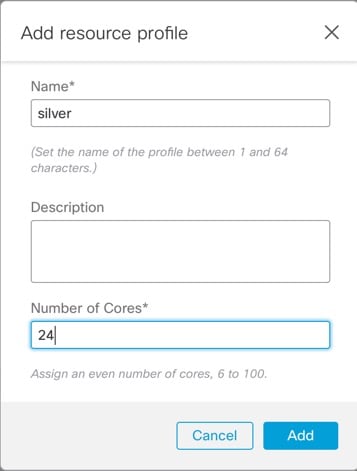
CPU and memory resources using resource profiles.
-
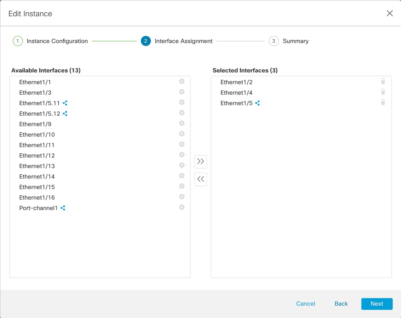
Interface configuration and assignment.
-
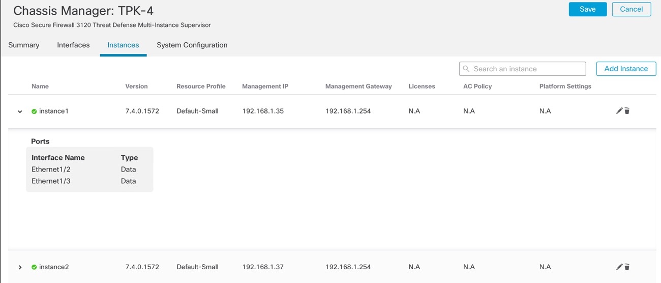
Deployment and monitoring of instances.
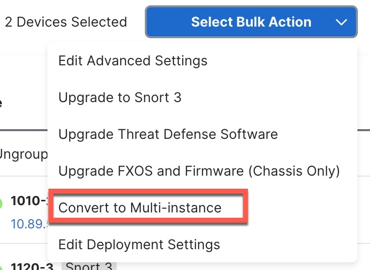
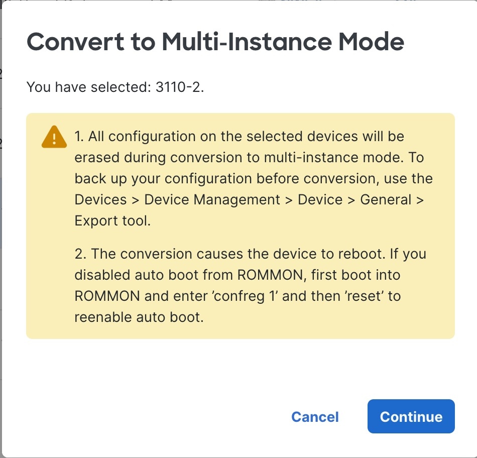
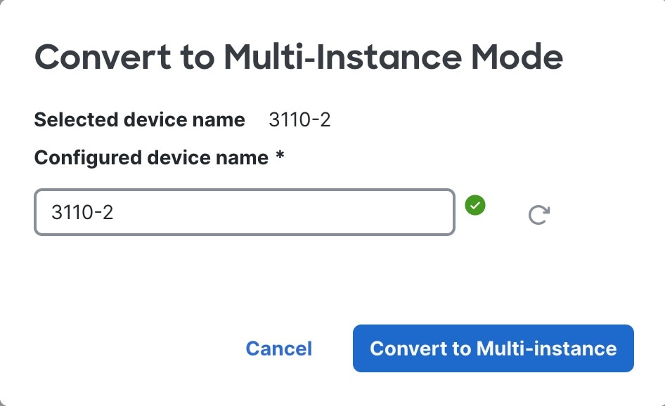
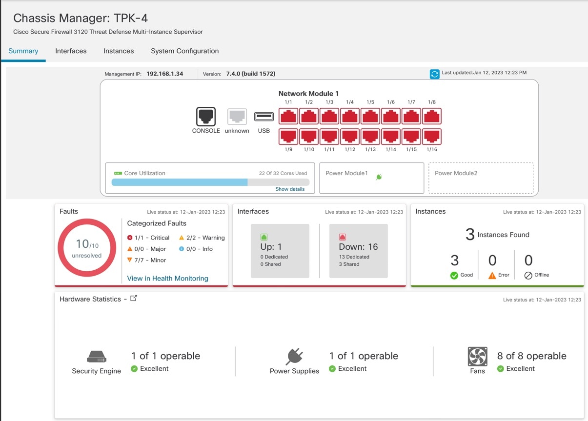
For a multi-instance device, you add the chassis to the management center and configure chassis-level settings on the Chassis Manager page.
Chassis Management Interface
Chassis Management
The chassis uses the dedicated Management interface on the device. Multi-instance mode does not support using a data interface for chassis management or DHCP addressing for the Management interface.
You can only configure the chassis Management interface at the threat defense CLI (at initial setup) or FXOS CLI (after you convert to multi-instance mode). See Change Chassis Management Settings at the FXOS CLI to change Management interface settings in multi-instance mode.
 Note |
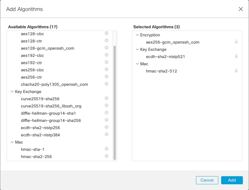
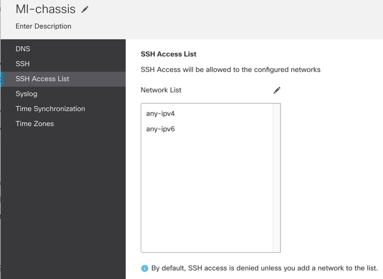
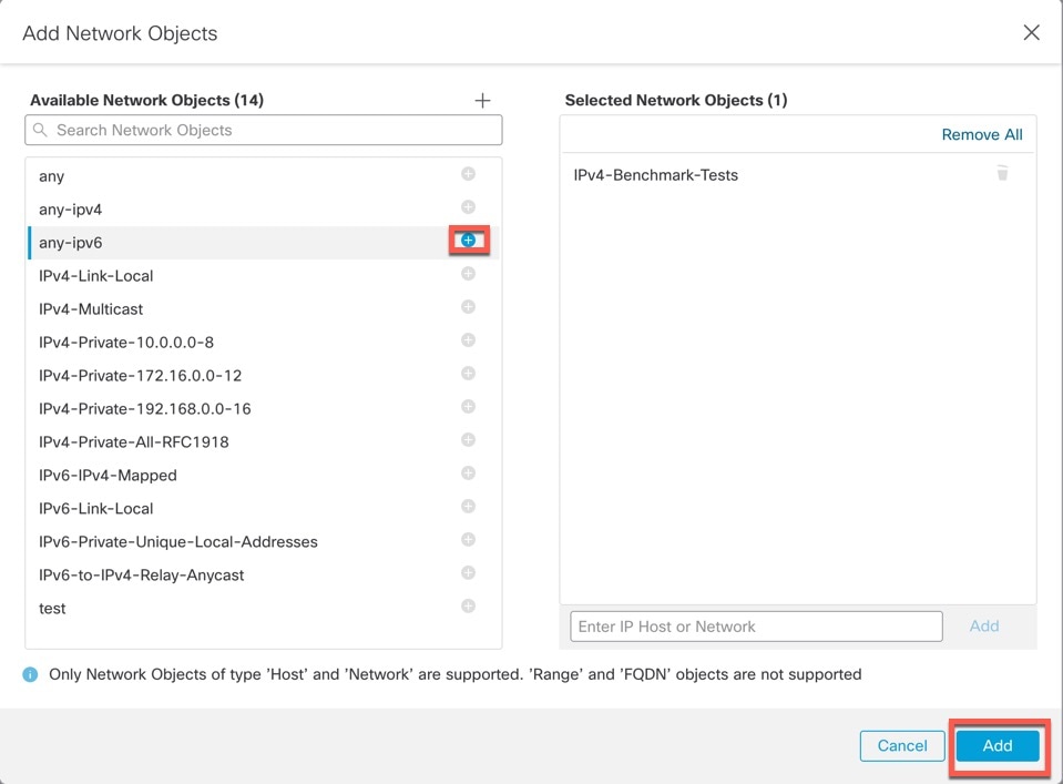
By default, SSH is not allowed to this interface in multi-instance mode unless you enable the SSH server and an SSH access list. This difference means that you can connect to the application-mode threat defense Management interface using SSH, but after you convert to multi-instance mode, you can no longer connect using SSH by default. See Configure SSH and SSH Access List. |
Instance Management
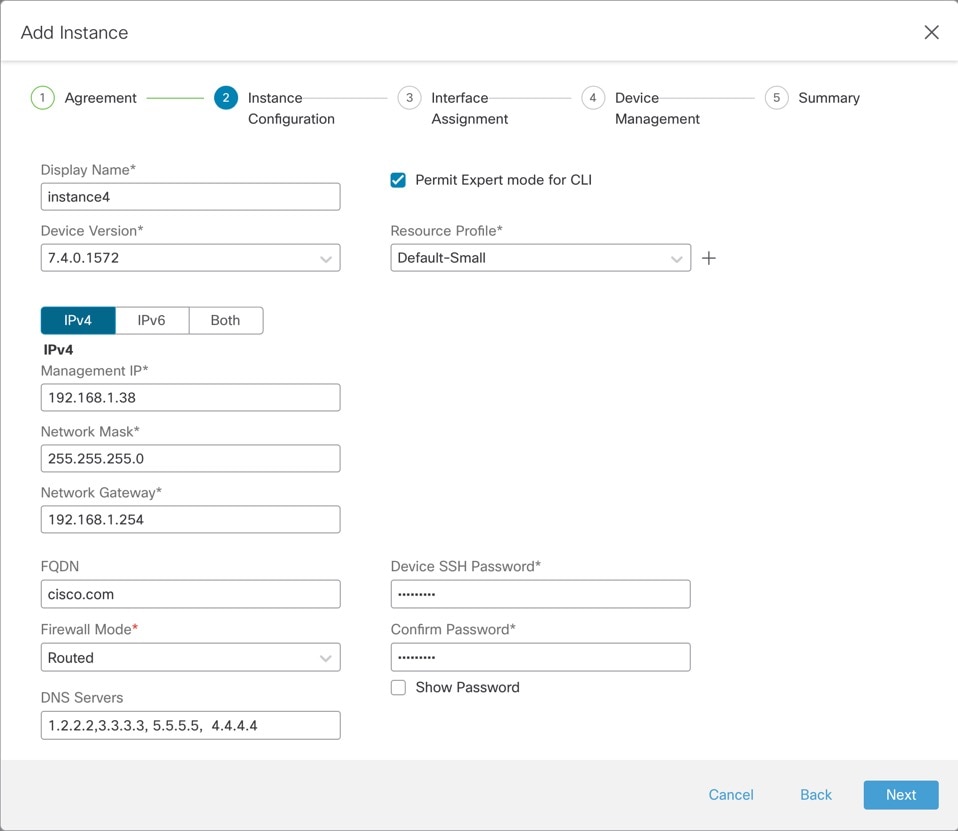
All instances share the chassis management interface, and each instance has its own IP address on the Management network. After you add the instance and specify the IP address, you can make changes to the network settings at the threat defense CLI.
The instance Management IP address allows SSH by default.
Instance Eventing Interface
The Secure Firewall 4200 includes a second dedicated interface, Management 1/2, that you can use for events. You can configure this interface at the threat defense CLI in each instance. Assign an IP address on the same network for each instance. See Configure an Event Interface.
Instance Interfaces
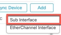
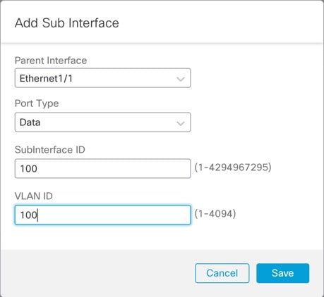
To provide flexible physical interface use for instances, you can create VLAN subinterfaces on the chassis and also share interfaces (VLAN or physical) between multiple instances. See Shared Interface Scalability and Configure a Subinterface.
 Note |
This chapter discusses chassis VLAN subinterfaces only. You can separately create subinterfaces within the threat defense instance. See Chassis Interfaces vs. Instance Interfaces for more information. |
Interface Types
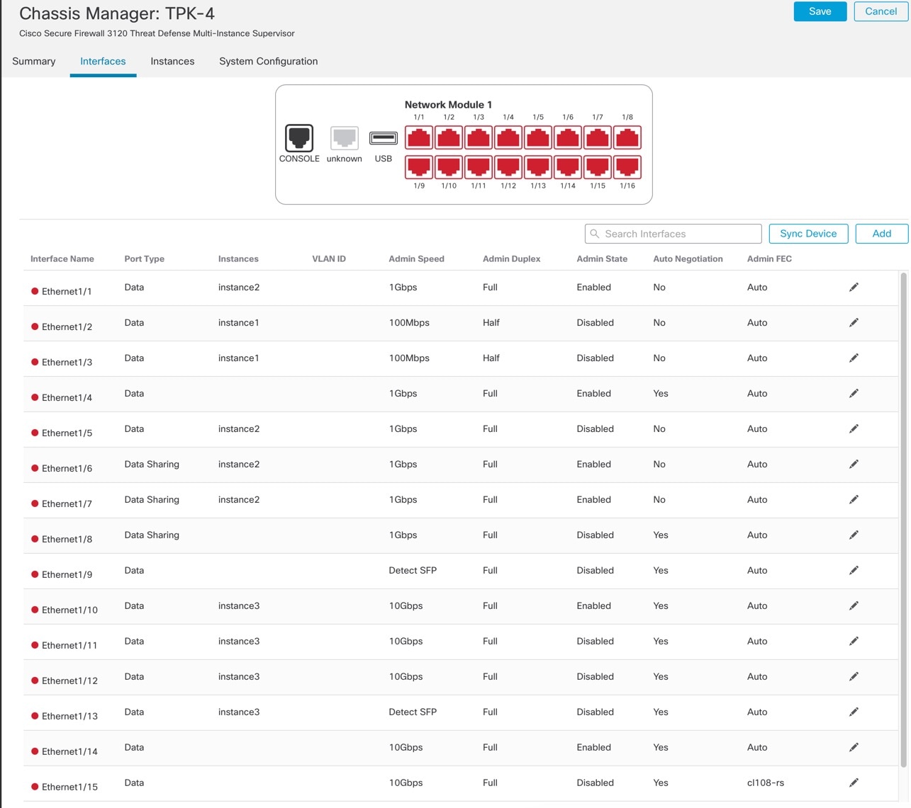
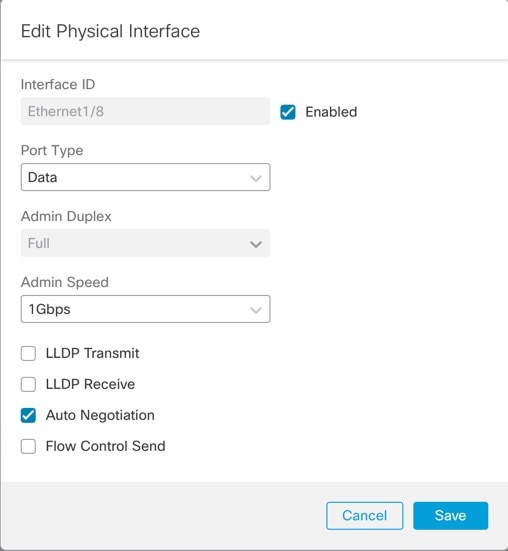
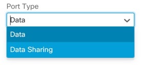
Physical interfaces, VLAN subinterfaces, and EtherChannel interfaces can be one of the following types:
-
Data—Use for regular data or the failover link. Data interfaces cannot be shared between instances, and instances cannot communicate over the backplane to other instances. For traffic on Data interfaces, all traffic must exit the chassis on one interface and return on another interface to reach another instance. You can add VLAN subinterfaces to a data interface to provide separate failover links per High Availability pair.
-
Data-sharing—Use for regular data. These data interfaces can be shared by one or more instances. Each instance can communicate over the backplane with all other instances that share this interface. Shared interfaces can affect the number of instances you can deploy. Shared interfaces are not supported for bridge group member interfaces (in transparent mode or routed mode), inline sets, passive interfaces, or failover links.
Chassis Interfaces vs. Instance Interfaces
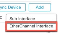
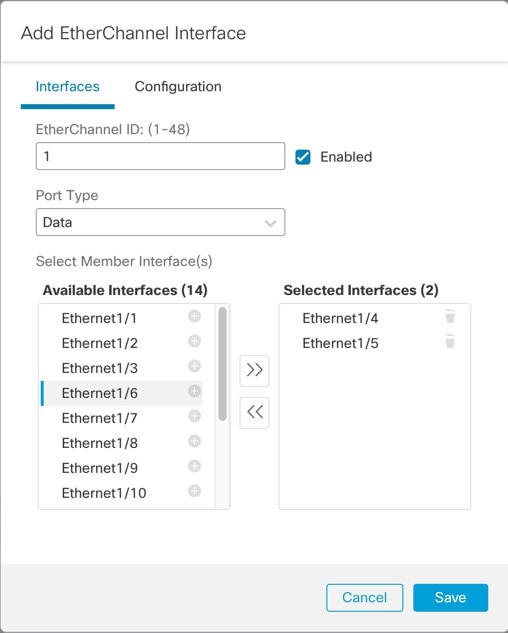
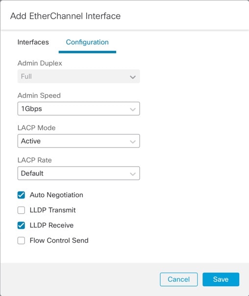
At the chassis level, you manage the basic Ethernet settings of physical interfaces, VLAN subinterfaces for instances, and EtherChannel interfaces. Within the instance, you configure higher level settings. For example, you can only create EtherChannels in the chassis; but you can assign an IP address to the EtherChannel within the instance.
The following sections describe the interaction between the chassis and the instance for interfaces.
VLAN Subinterfaces
You can create VLAN subinterfaces within the instance, just as you would for any device.
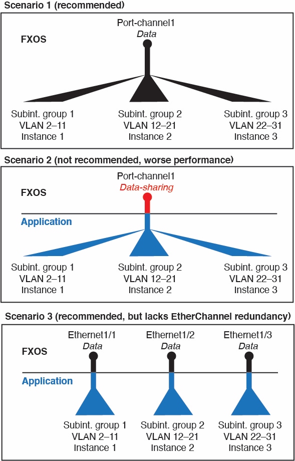
You can also create VLAN subinterfaces in the chassis. The instance-defined subinterfaces are not subject to the chassis limit. Choosing in which location to create subinterfaces depends on your network deployment and personal preference. For example, to share a subinterface, you must create the subinterface on the chassis. Another scenario that favors chassis subinterfaces comprises allocating separate subinterface groups on a single interface to multiple instances. For example, you want to use Port-channel1 with VLAN 2–11 on instance A, VLAN 12–21 on instance B, and VLAN 22–31 on instance C. If you create these subinterfaces in the instance, then you would have to share the parent interface in the chassis, which may not be desirable. See the following illustration that shows the three ways you can accomplish this scenario:
Independent Interface States in the Chassis and in the Instance
You can administratively enable and disable interfaces in both the chassis and in the instance. For an interface to be operational, the interface must be enabled in both locations. Because the interface state is controlled independently, you may have a mismatch between the chassis and instance.
The default state of an interface within the instance depends on the type of interface. For example, the physical interface or EtherChannel is disabled by default within the instance, but a subinterface is enabled by default.
Shared Interface Scalability
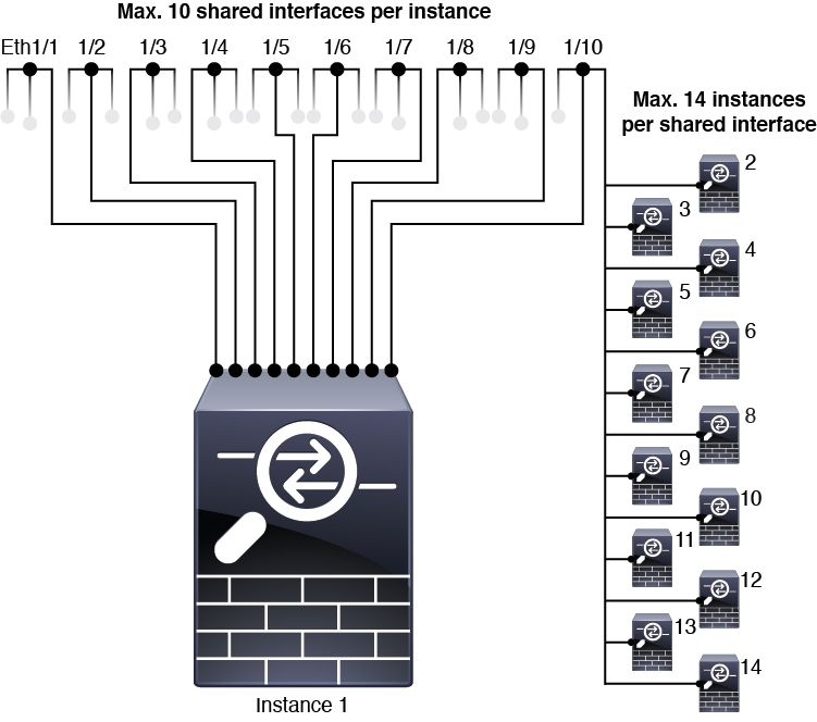
Instances can share data-sharing type interfaces. This capability lets you conserve physical interface usage as well as support flexible networking deployments. When you share an interface, the chassis uses unique MAC addresses to forward traffic to the correct instance. However, shared interfaces can cause the forwarding table to grow large due to the need for a full mesh topology within the chassis (every instance must be able to communicate with every other instance that is sharing the same interface). Therefore, there are limits to how many interfaces you can share.
In addition to the forwarding table, the chassis maintains a VLAN group table for VLAN subinterface forwarding. You can create up to 500 VLAN subinterfaces.
See the following limits for shared interface allocation:
Shared Interface Best Practices
For optimal scalability of the forwarding table, share as few interfaces as possible. Instead, you can create up to 500 VLAN subinterfaces on one or more physical interfaces and then divide the VLANs among the container instances.
When sharing interfaces, follow these practices in the order of most scalable to least scalable:
-
Best—Share subinterfaces under a single parent, and use the same set of subinterfaces with the same group of instances.
For example, create a large EtherChannel to bundle all of your like-kind interfaces together, and then share subinterfaces of that EtherChannel: Port-Channel1.2, 3, and 4 instead of Port-Channel2, Port-Channel3, and Port-Channel4. When you share subinterfaces from a single parent, the VLAN group table provides better scaling of the forwarding table than when sharing physical/EtherChannel interfaces or subinterfaces across parents.
Figure 2. Best: Shared Subinterface Group on One Parent 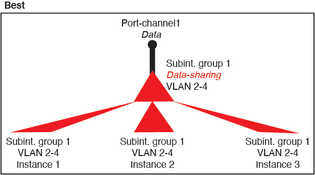
If you do not share the same set of subinterfaces with a group of instances, your configuration can cause more resource usage (more VLAN groups). For example, share Port-Channel1.2, 3, and 4 with instances 1, 2, and 3 (one VLAN group) instead of sharing Port-Channel1.2 and 3 with instances 1 and 2, while sharing Port-Channel1.3 and 4 with instance 3 (two VLAN groups).
Figure 3. Good: Sharing Multiple Subinterface Groups on One Parent 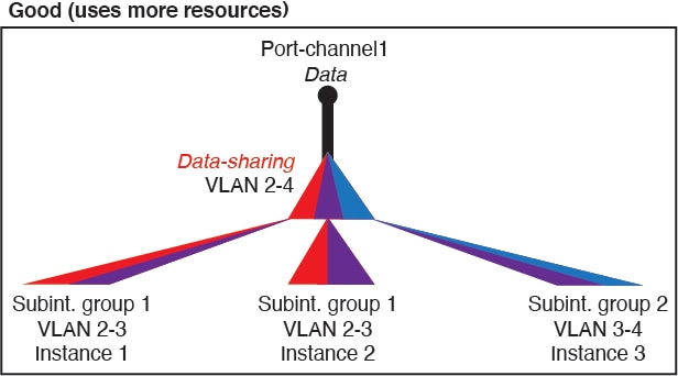
-
Fair—Share subinterfaces across parents.
For example, share Port-Channel1.2, Port-Channel2.3, and Port-Channel3.4 instead of Port-Channel2, Port-Channel4, and Port-Channel4. Although this usage is not as efficient as only sharing subinterfaces on the same parent, it still takes advantage of VLAN groups.
Figure 4. Fair: Shared Subinterfaces on Separate Parents 
-
Worst—Share individual parent interfaces (physical or EtherChannel).
This method uses the most forwarding table entries.
Figure 5. Worst: Shared Parent Interfaces 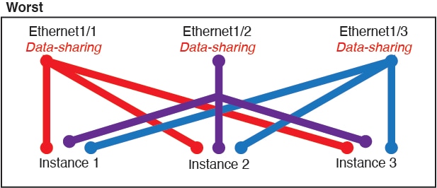
How the Chassis Classifies Packets
Each packet that enters the chassis must be classified, so that the chassis can determine to which instance to send a packet.
-
Unique Interfaces—If only one instance is associated with the ingress interface, the chassis classifies the packet into that instance. For bridge group member interfaces (in transparent mode or routed mode), inline sets, or passive interfaces, this method is used to classify packets at all times.
-
Unique MAC Addresses—The chassis automatically generates unique MAC addresses for all interfaces, including shared interfaces. If multiple instances share an interface, then the classifier uses unique MAC addresses assigned to the interface in each instance. An upstream router cannot route directly to an instance without unique MAC addresses. You can also set the MAC addresses manually when you configure each interface within the application.
 Note |
If the destination MAC address is a multicast or broadcast MAC address, the packet is duplicated and delivered to each instance. |
Classification Examples
Packet Classification with a Shared Interface Using MAC Addresses
The following figure shows multiple instances sharing an outside interface. The classifier assigns the packet to Instance C because Instance C includes the MAC address to which the router sends the packet.
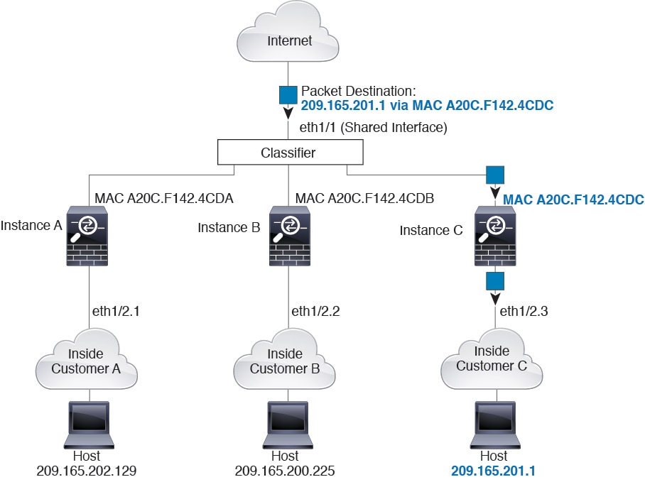
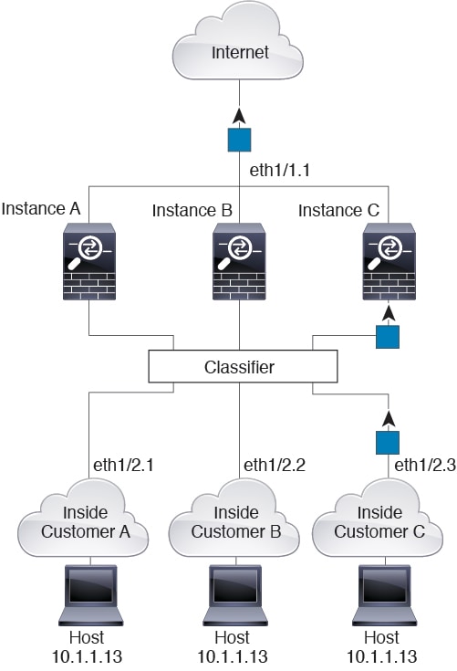
Incoming Traffic from Inside Networks
Note that all new incoming traffic must be classified, even from inside networks. The following figure shows a host on the Instance C inside network accessing the internet. The classifier assigns the packet to Instance C because the ingress interface is Ethernet 1/2.3, which is assigned to Instance C.
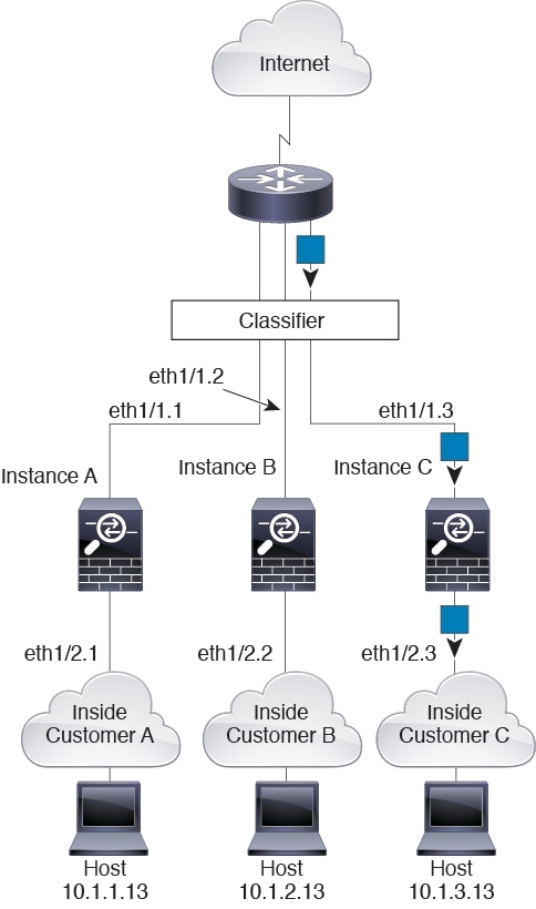
Transparent Firewall Instances
For transparent firewalls, you must use unique interfaces. The following figure shows a packet destined to a host on the Instance C inside network from the internet. The classifier assigns the packet to Instance C because the ingress interface is Ethernet 1/2.3, which is assigned to Instance C.
Inline Sets
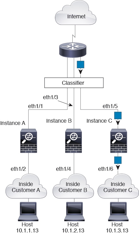
For inline sets, you must use unique interfaces and they must be physical interfaces or EtherChannels. The following figure shows a packet destined to a host on the Instance C inside network from the internet. The classifier assigns the packet to Instance C because the ingress interface is Ethernet 1/5, which is assigned to Instance C.
Cascading Instances
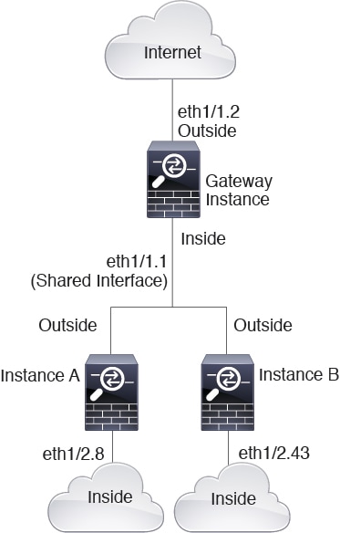
Placing an instance directly in front of another instance is called cascading instances; the outside interface of one instance is the same interface as the inside interface of another instance. You might want to cascade instances if you want to simplify the configuration of some instances by configuring shared parameters in the top instance.
The following figure shows a gateway instance with two instances behind the gateway.
 Note |
Do not use cascading instances (using a shared interface) with High Availability. After a failover occurs and the standby unit rejoins, MAC addresses can overlap temporarily and cause an outage. You should instead use unique interfaces for the gateway instance and inside instance using an external switch to pass traffic between the instances. |
Typical Multi-Instance Deployment
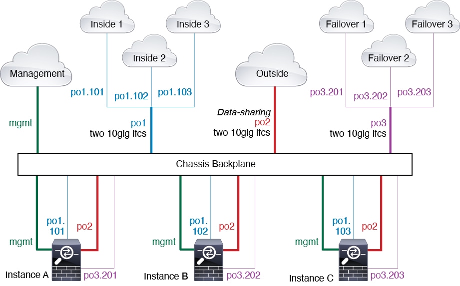
The following example includes three container instances in routed firewall mode. They include the following interfaces:
-
Management—All instances and the chassis use the dedicated Management interface. Within each instance (and the chassis), the interface uses a unique IP address on the same management network.
-
Inside—Each instance uses a subinterface on Port-Channel1 (data type). This EtherChannel includes two 10 Gigibit Ethernet interfaces. Each subinterface is on a separate network.
-
Outside—All instances use the Port-Channel2 interface (data-sharing type). This EtherChannel includes two 10 Gigibit Ethernet interfaces. Within each application, the interface uses a unique IP address on the same outside network.
-
Failover—Each instance uses a subinterface on Port-Channel3 (data type). This EtherChannel includes two 10 Gigibit Ethernet interfaces. Each subinterface is on a separate network.
Automatic MAC Addresses for Instance Interfaces
The chassis automatically generates MAC addresses for instance interfaces, and guarantees that a shared interface in each instance uses a unique MAC address.
If you manually assign a MAC address to a shared interface within the instance, then the manually-assigned MAC address is used. If you later remove the manual MAC address, the autogenerated address is used. In the rare circumstance that the generated MAC address conflicts with another private MAC address in your network, we suggest that you manually set the MAC address for the interface within the instance.
Because autogenerated addresses start with A2, you should not start manual MAC addresses with A2 due to the risk of overlapping addresses.
The chassis generates the MAC address using the following format:
A2xx.yyzz.zzzz
Where xx.yy is a user-defined prefix or a system-defined prefix, and zz.zzzz is an internal counter generated by the chassis. The system-defined prefix matches the lower 2 bytes of the first MAC address in the burned-in MAC address pool that is programmed into the IDPROM. Use connect fxos , then show module to view the MAC address pool. For example, if the range of MAC addresses shown for module 1 is b0aa.772f.f0b0 to b0aa.772f.f0bf, then the system prefix will be f0b0.
The user-defined prefix is an integer that is converted into hexadecimal. For an example of how the user-defined prefix is used, if you set a prefix of 77, then the chassis converts 77 into the hexadecimal value 004D (yyxx). When used in the MAC address, the prefix is reversed (xxyy) to match the chassis native form:
A24D.00zz.zzzz
For a prefix of 1009 (03F1), the MAC address is:
A2F1.03zz.zzzz
Performance Scaling Factor for Multi-Instance Mode
The maximum throughput (connections, VPN sessions) for a platform is calculated for an appliance mode device's use of memory and CPU (and this value is shown in show resource usage ). If you use multiple instances, then you need to calculate the throughput based on the percentage of CPU cores that you assign to the instance. For example, if you use an instance with 50% of the cores, then you should initially calculate 50% of the throughput. Moreover, the throughput available to an instance may be less than that available to an appliance.
For detailed instructions on calculating the throughput for instances, see https://www.cisco.com/c/en/us/products/collateral/security/firewalls/white-paper-c11-744750.html.
Instances and High Availability
You can use High Availability using an instance on 2 separate chassis; for example, if you have 2 chassis, each with 10 instances, you can create 10 High Availability pairs. You can also have standalone instances on the same chassis as High Availability instances. For detailed requirements, see Requirements and Prerequisites for Instances.
 Note |
Clustering is not supported. |

 to rerun the readiness check so you can continue.



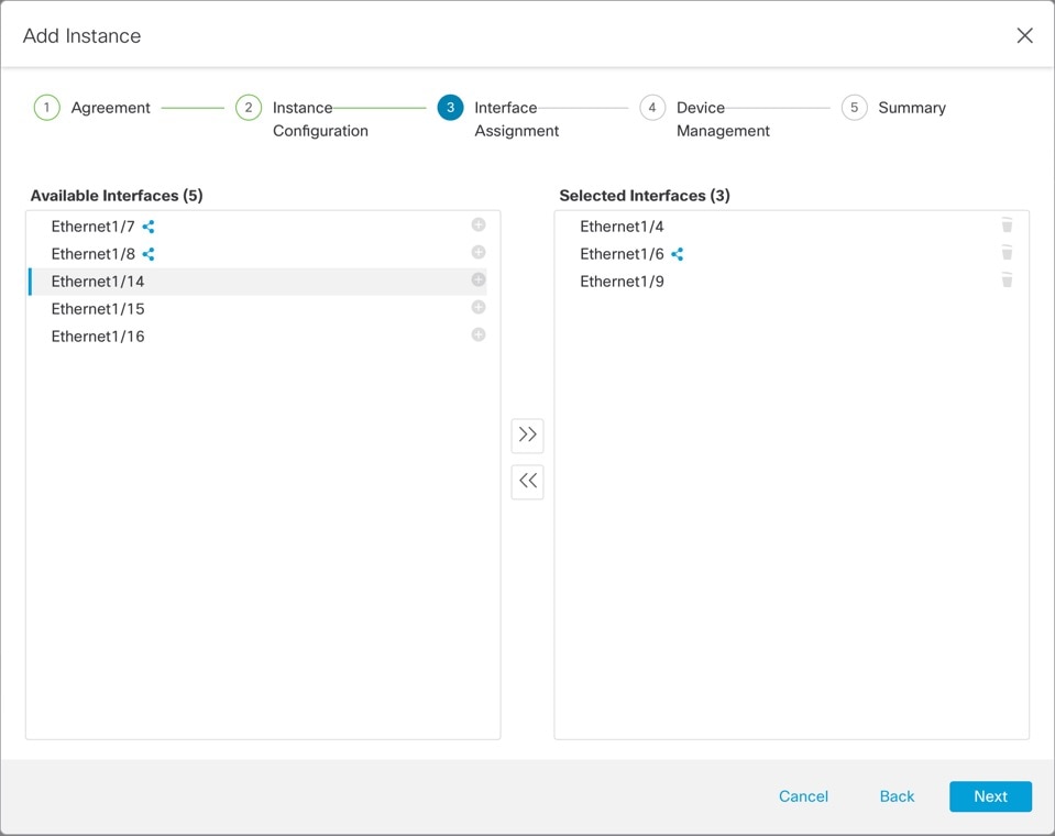
 ).
).
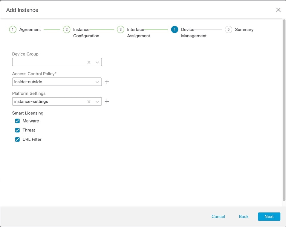
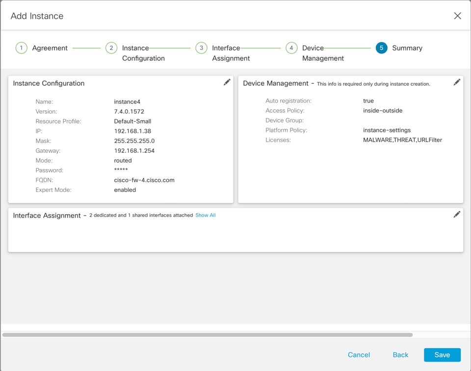


 Feedback