About IPS Interfaces
You can configure IPS-only passive interfaces, passive ERSPAN interfaces, and inline sets. IPS-only mode interfaces bypass many firewall checks and only support IPS security policy (Snort). You might want to implement IPS-only interfaces if you have a separate firewall protecting these interfaces and do not want the overhead of firewall functions.
IPS-only mode interfaces bypass many firewall checks and only support IPS security policy (Snort). You might want to implement IPS-only interfaces if you have a separate firewall protecting these interfaces and do not want the overhead of firewall functions.
 Note |
The firewall mode only affects regular firewall interfaces, and not IPS-only interfaces such as inline sets or passive interfaces. IPS-only interfaces can be used in both firewall modes. |
Inline Sets
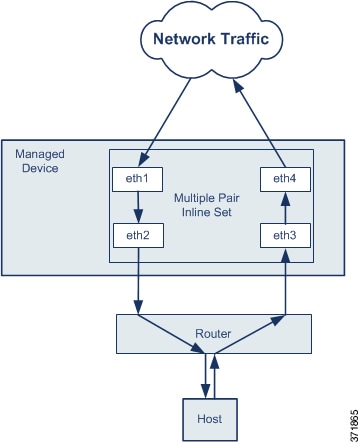
An inline set acts like a bump on the wire, and binds one or more interface pairs together to slot into an existing network. This function allows the threat defense to be installed in any network environment without the configuration of adjacent network devices. Inline interfaces receive all traffic unconditionally, but all traffic received on these interfaces is retransmitted out of the other interface in the inline pair unless explicitly dropped. When you have multiple inline pairs in an inline set, traffic can only pass between the interfaces in the pair; it can't pass between interfaces in different pairs.
With tap mode, the threat defense is deployed inline, but the network traffic flow is undisturbed. Instead, the threat defense makes a copy of each packet so that it can analyze the packets. Note that rules of these types do generate intrusion events when they are triggered, and the table view of intrusion events indicates that the triggering packets would have dropped in an inline deployment. There are benefits to using tap mode with FTDs that are deployed inline. For example, you can set up the cabling between the threat defense and the network as if the threat defense were inline and analyze the kinds of intrusion events the threat defense generates. Based on the results, you can modify your intrusion policy and add the drop rules that best protect your network without impacting its efficiency. When you are ready to deploy the threat defense inline, you can disable tap mode and begin dropping suspicious traffic without having to reconfigure the cabling between the threat defense and the network.
 Note |
Tap mode significantly impacts threat defense performance, depending on the traffic. |
 Note |
Inline sets might be familiar to you as "transparent inline sets," but the inline interface type is unrelated to the transparent firewall mode or the firewall-type interfaces. |
Multiple Inline Pairs and Asynchronous Routing
You can configure the interfaces to route traffic between a host on your network and external hosts through different inline pairs, depending on whether the traffic is inbound or outbound. This is an asynchronous routing configuration. If you deploy asynchronous routing, but you include only one inline pair in an inline set, the device might not correctly analyze your network traffic because it might see only half of the traffic.
Adding multiple inline pairs to the same inline set lets the system identify the inbound and outbound traffic as part of the same traffic flow. For passive interfaces only, you can also achieve this by including the interface pairs in the same security zone.

 Note |
If you assign multiple inline pairs to a single inline set, but you experience issues with duplicate traffic, you might need to reassign your inline pairs to separate inline sets or modify your security zones. |
Passive Interfaces
Passive interfaces monitor traffic flowing across a network using a switch SPAN or mirror port. The SPAN or mirror port allows for traffic to be copied from other ports on the switch. This function provides the system visibility within the network without being in the flow of network traffic. When you configure the threat defense in a passive deployment, the threat defense cannot take certain actions such as blocking or shaping traffic. Passive interfaces receive all traffic unconditionally. and no traffic received on these interfaces is retransmitted. Encapsulated remote switched port analyzer (ERSPAN) interfaces allow you to monitor traffic from source ports distributed over multiple switches, and uses GRE to encapsulate the traffic. ERSPAN interfaces are only allowed when the threat defense is in routed firewall mode.
 Note |
Using SR-IOV interfaces as passive interfaces on NGFWv is not supported on some Intel network adapters (such as Intel X710 or 82599) using SR-IOV drivers due to a promiscuous mode restriction. In such cases, use a network adapter that supports this functionality. See Intel Ethernet Products for more information on Intel network adapters. |
About Hardware Bypass for Inline Sets
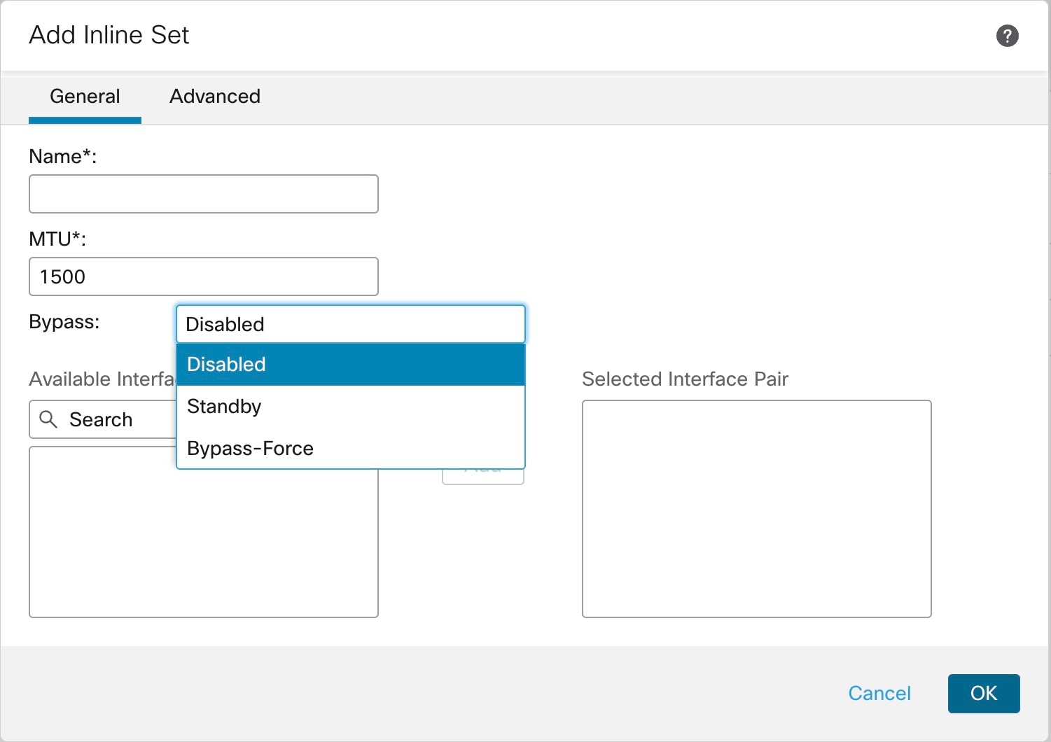
For certain interface modules on the supported models (see Requirements and Prerequisites for Inline Sets), you can enable the Hardware Bypass feature. Hardware Bypass ensures that traffic continues to flow between an inline interface pair during a power outage. This feature can be used to maintain network connectivity in the case of software or hardware failures.
Hardware Bypass Triggers
Hardware Bypass can be triggered in the following scenarios:
-
Threat Defense crash
-
Threat Defense reboot
-
Security Module reboot
-
Chassis crash
-
Chassis reboot
-
Manual trigger
-
Chassis power loss
-
Security Module power loss
 Note |
Hardware bypass is intended for unplanned/unexpected failure scenarios, and is not automatically triggered during planned software upgrades. Hardware bypass only engages at the end of a planned upgrade process, when the threat defense application reboots. |
Hardware Bypass Switchover
When switching from normal operation to hardware bypass or from hardware bypass back to normal operation, traffic may be interrupted for several seconds. A number of factors can affect the length of the interruption; for example, copper port auto-negotiation; behavior of the optical link partner such as how it handles link faults and de-bounce timing; spanning tree protocol convergence; dynamic routing protocol convergence; and so on. During this time, you may experience dropped connections.
You may also experience dropped connections due to application identification errors when analyzing connections midstream after the return to normal operations.
Failsafe Snort Fail Open vs. Hardware Bypass
Inline sets include a software failure setting called "failsafe." If a software failure in the IPS subsystem would prevent traffic from passing through the inline set, then the failsafe option allows the traffic to keep flowing. Failsafe is supported on any interface pair except those in tap mode, not just the ones supported for the Hardware Bypass feature.
For inline sets other than those in tap mode, you can use the Snort Fail Open option to either drop traffic or allow traffic to pass without inspection when the Snort process is busy or down. Snort Fail Open is supported on all inline sets except those in tap mode, not just on interfaces that support Hardware Bypass.
The Hardware Bypass functionality allows traffic to flow during a hardware failure, including a complete power outage, and certain limited software failures. A software failure that triggers failsafe Snort Fail Open does not trigger a Hardware Bypass.
Hardware Bypass Status
If the system has power, then the Bypass LED indicates the Hardware Bypass status. See the Firepower chassis hardware installation guide for LED descriptions.

 Feedback