- Device Manager Help
- Configuring Cisco DCNM-SAN Server
- Configuring Authentication in Cisco DCNM-SAN
- Configuring Cisco DCNM-SAN Client
- Device Manager
- Configuring Performance Manager
- Configuring High Availability
- Configuring Trunking
- Configuring PortChannels
- Configuring N Port Virtualization
- Configuring Interfaces
- Configuration of Fibre Channel Interfaces
- Using the CFS Infrastructure
- Configuring SNMP
- Configuring Domain Parameters
- Configuring and Managing Zones
- Configuring FCoE
- Configuring Dense Wavelength Division Multiplexing
- Configuring and Managing VSANs
- Discovering SCSI Targets
- Configuring SAN Device Virtualization
- Configuring Fibre Channel Routing Services and Protocols
- Managing FLOGI, Name Server, FDMI, and RSCN Databases
- Configuring FICON
- Creating Dynamic VSANs
- Distributing Device Alias Services
- Configuring Advanced Fabric Features
- Configuring Users and Common Role
- Configuring Security Features on an External AAA Server
- Configuring Certificate Authorities and Digital Certificates
- Configuring FC-SP and DHCHAP
- Configuring Cisco TrustSec Fibre Channel Link Encryption
- Configuring FIPS
- Configuring IPv4 and IPv6 Access Control Lists
- Configuring IPsec Network Security
- Configuring Port Security
- Configuring Fabric Binding
- Configuring FCIP
- Configuring the SAN Extension Tuner
- Configuring iSCSI
- Configuring IP Services
- Configuring IP Storage
- Configuring IPv4 for Gigabit Ethernet Interfaces
- Configuring IPv6 for Gigabit Ethernet Interfaces
- Configuring SCSI Flow Services
- Configuring SCSI Flow Statistics
- Configuring Fibre Channel Write Acceleration
- Monitoring the Network
- Monitoring Performance
- Configuring Call Home
- Configuring System Message Logging
- Scheduling Maintenance Jobs
- Configuring RMON
- Configuring Fabric Configuration Server
- Monitoring Network Traffic Using SPAN
- Monitoring System Processes and Logs
- Configuring QoS
- Configuring Port Tracking
- Configuring FlexAttach Virtual pWWN
- Configuring Interface Buffers
- Verifying Ethernet Interfaces
- Information About IP Storage
- IPS Module Upgrade
- MPS-14/2 Module Upgrade
- Supported Hardware
- Gigabit Ethernet Interfaces for IPv4 Configuration
- Basic Gigabit Ethernet Configuration
- IPS Module Core Dumps
- About VLANs for Gigabit Ethernet
- Interface Subnet Requirements
- Verifying Gigabit Ethernet Connectivity
- Gigabit Ethernet High Availability
- VRRP for iSCSI and FCIP Services
- About Ethernet PortChannel Aggregation
- CDP
- Licensing Requirements for IP Storage
- Guidelines and Limitations
- Default Settings
- Configuring IP Storage
- Verifying IP Storage Configuration
- Field Descriptions for IP Storage
- FCIP Profiles
- FCIP Tunnels
- FCIP Tunnels (Advanced)
- FCIP Tunnels (FICON TA)
- FCIP Tunnels Statistics
- FCIP XRC Statistics
- iSCSI Connection
- iSCSI Initiators
- iSCSI Targets
- iSCSI Session Initiators
- Module Control
- iSCSI Global
- iSCSI Session Statistics
- iSCSI iSLB VRRP
- iSCSI Initiator Access
- Initiator Specific Target
- iSCSI Initiator PWWN
- iSCSI Sessions
- iSCSI Sessions Detail
- Additional References
Configuring IP Storage
Cisco MDS 9000 Family IP storage (IPS) services extend the reach of Fibre Channel SANs by using open-standard, IP-based technology. The switch connects separated SAN islands using Fibre Channel over IP (FCIP), and it allows IP hosts to access Fibre Channel storage using the iSCSI protocol.

Note FCIP and iSCSI features are specific to the IPS module and are available in Cisco MDS 9200 Switches or Cisco MDS 9500 Directors.
The Cisco MDS 9216I switch and the 14/2 Multiprotocol Services (MPS-14/2) module also allow you to use Fibre Channel, FCIP, and iSCSI features. The MPS-14/2 module is available for use in any switch in the Cisco MDS 9200 Series or Cisco MDS 9500 Series.
Information About IP Storage
The IP Storage services module (IPS module) and the MPS-14/2 module allow you to use FCIP and iSCSI features. FCIP and iSCSI features are specific to the IPS module and are available in Cisco MDS 9200 Switches or Cisco MDS 9500 Directors. The switch connects separated SAN islands using Fibre Channel over IP (FCIP), and it allows IP hosts to access Fibre Channel storage using the iSCSI protocol.
- FCIP—FCIP transports Fibre Channel frames transparently over an IP network between two Cisco MDS 9000 Family switches or other FCIP standards-compliant devices.
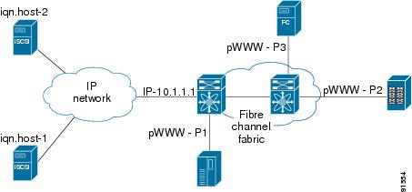
- iSCSI—The IPS module provides IP hosts access to Fibre Channel storage devices. The IP host sends SCSI commands encapsulated in iSCSI protocol data units (PDUs) to a Cisco MDS 9000 Family switch IPS port over a TCP/IP connection. At this point, the commands are routed from an IP network into a Fibre Channel network and forwarded to the intended target.
The IP Storage services module (IPS module) and the MPS-14/2 module allow you to use FCIP and iSCSI features. Both modules integrate seamlessly into the Cisco MDS 9000 Family, and support the full range of features available on other switching modules, including VSANs, security, and traffic management. The following types of storage services modules are currently available for use in any switch in the Cisco MDS 9200 Series or in the Cisco MDS 9500 Series:
- The 4-port, hot-swappable IPS module (IPS-4) has four Gigabit Ethernet ports.
- The 8-port, hot-swappable IPS module (IPS-8) has eight Gigabit Ethernet ports.
- The MPS-14/2 module has 14 Fibre Channel ports (numbered 1 through 14) and two Gigabit Ethernet ports (numbered 1 and 2).
Gigabit Ethernet ports in these modules can be configured to support the FCIP protocol, the iSCSI protocol, or both protocols simultaneously:
- FCIP—FCIP transports Fibre Channel frames transparently over an IP network between two Cisco MDS 9000 Family switches or other FCIP standards-compliant devices.
Figure 42-1 shows how the IPS module is used in different FCIP scenarios.
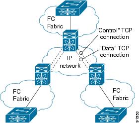
- iSCSI—The IPS module provides IP hosts access to Fibre Channel storage devices. The IP host sends SCSI commands encapsulated in iSCSI protocol data units (PDUs) to a Cisco MDS 9000 Family switch IPS port over a TCP/IP connection. At this point, the commands are routed from an IP network into a Fibre Channel network and forwarded to the intended target.
Figure 42-2 depicts the iSCSI scenarios in which the IPS module is used.
This section contains the following topics:
- IPS Module Upgrade
- MPS-14/2 Module Upgrade
- Supported Hardware
- Gigabit Ethernet Interfaces for IPv4 Configuration
- Basic Gigabit Ethernet Configuration
- IPS Module Core Dumps
- About VLANs for Gigabit Ethernet
- Interface Subnet Requirements
- Verifying Gigabit Ethernet Connectivity
- Gigabit Ethernet High Availability
- VRRP for iSCSI and FCIP Services
- About Ethernet PortChannel Aggregation
- CDP
IPS Module Upgrade

Caution A software upgrade is only disruptive for the IPS module. The NX-OS software continues to support nondisruptive software upgrades for Fibre Channel modules in the switch and for the switch itself.
IPS modules use a rolling upgrade install mechanism where each module in a given switch can only be upgraded in sequence. To guarantee a stable state, each IPS module in a switch requires a 5-minute delay before the next IPS module is upgraded.
MPS-14/2 Module Upgrade
Caution A software upgrade is only partially disruptive for the MPS-14/2 module. The NX-OS software continues to support nondisruptive software upgrades for Fibre Channel modules in the switch and for the switch itself.
The MPS-14/2 modules have 14 Fibre Channel ports (nondisruptive upgrade) and two Gigabit Ethernet ports (disruptive upgrade). MPS-14/2 modules use a rolling upgrade install mechanism for the two Gigabit Ethernet ports where each module in a given switch can only be upgraded in sequence. To guarantee a stable state, each MPS-14/2 module in a switch requires a 5-minute delay before the next module is upgraded.
Supported Hardware
You can configure the FCIP and iSCSI features using one or more of the following hardware:
- IPS-4 and IPS-8 modules (refer to the Cisco MDS 9200 Series Hardware Installation Guide or the Cisco MDS 9500 Series Hardware Installation Guide for more information)
- MPS-14/2 module (refer to the Cisco MDS 9200 Series Hardware Installation Guide or the Cisco MDS 9500 Series Hardware Installation Guide for more information).
Note In both the MPS-14/2 module and the Cisco MDS 9216i integrated supervisor module, the port numbering differs for the Fibre Channel ports and the Gigabit Ethernet ports. The Fibre Channel ports are numbered from 1 through 14 and the Gigabit Ethernet ports are numbered 1 and 2.
Gigabit Ethernet Interfaces for IPv4 Configuration
Both FCIP and iSCSI rely on TCP/IP for network connectivity. On each IPS module or MPS-14/2 module, connectivity is provided in the form of Gigabit Ethernet interfaces that are appropriately configured.
A new port mode, called IPS, is defined for Gigabit Ethernet ports on each IPS module or MPS-14/2 module. IP storage ports are implicitly set to IPS mode, so it can be used to perform only iSCSI and FCIP storage functions. IP storage ports do not bridge Ethernet frames or route other IP packets.
Each IPS port represents a single virtual Fibre Channel host in the Fibre Channel SAN. All iSCSI hosts connected to this IPS port are merged and multiplexed through the single Fibre Channel host.
Note For information about configuring FCIP, see Chapter38, “Configuring FCIP” For information about configuring iSCSI, see Chapter40, “Configuring iSCSI”
In large scale iSCSI deployments where the Fibre Channel storage subsystems require explicit LUN access control for every host device, use of proxy-initiator mode simplifies the configuration.
Note The Gigabit Ethernet interfaces on the MPS-14/2 module do not support EtherChannel.
Note To configure IPv6 on a Gigabit Ethernet interface, see the Security Configuration Guide, Cisco DCNM for SAN.

Tip Gigabit Ethernet ports on any IPS module or MPS-14/2 module should not be configured in the same Ethernet broadcast domain as the management Ethernet port—they should be configured in a different broadcast domain, either by using separate standalone hubs or switches or by using separate VLANs.
Basic Gigabit Ethernet Configuration
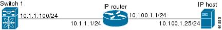
Figure 42-3 shows an example of a basic Gigabit Ethernet IP version 4 (IPv4) configuration.
Figure 42-3 Gigabit Ethernet IPv4 Configuration Example
The port on the Ethernet switch to which the Gigabit Ethernet interface is connected should be configured as a host port (also known as access port) instead of a switch port. Spanning tree configuration for that port (on the Ethernet switch) should disabled. This helps avoid the delay in the management port coming up due to delay from Ethernet spanning tree processing that the Ethernet switch would run if enabled. For Cisco Ethernet switches, use either the switchport host command in Cisco IOS or the set port host command in Catalyst OS.
IPS Module Core Dumps
IPS core dumps are different from the system’s kernel core dumps for other modules. When the IPS module’s operating system (OS) unexpectedly resets, it is useful to obtain a copy of the memory image (called a IPS core dump) to identify the cause of the reset. Under that condition, the IPS module sends the core dump to the supervisor module for storage. Cisco MDS switches have two levels of IPS core dumps:
- Partial core dumps (default)—Each partial core dump consists of four parts (four files). All four files are saved in the active supervisor module.
Use the show cores command to list these files.
- Full core dumps—Each full core dump consists of 75 parts (75 files). The IPS core dumps for the MPS-14/2 module and the Cisco MDS 9216i Switch only contains 38 parts. This dump cannot be saved on the supervisor module because of its large space requirement. They are copied directly to an external TFTP server.
Use the system cores tftp: command to configure an external TFTP server to copy the IPS core dump (and other core dumps).
Interface Descriptions Configuration
See the Interfaces Configuration Guide, Cisco DCNM for SAN for details on configuring the switch port description for any interface.
Beacon Mode Configuration
See the Interfaces Configuration Guide, Cisco DCNM for SAN for details on configuring the beacon mode for any interface.
Autonegotiation Configuration
By default, autonegotiation is enabled all Gigabit Ethernet interface. You can enable or disable autonegotiation for a specified Gigabit Ethernet interface. When autonegotiation is enabled, the port automatically detects the speed or pause method, and duplex of incoming signals based on the link partner. You can also detect link up conditions using the autonegotiation feature.
MTU Frame Size Configuration
You can configure the interfaces on a switch to transfer large (or jumbo) frames on a port. The default IP maximum transmission unit (MTU) frame size is 1500 bytes for all Ethernet ports. By configuring jumbo frames on a port, the MTU size can be increased up to 9000 bytes.
Note The minimum MTU size is 576 bytes.
Tip MTU changes are disruptive, all FCIP links and iSCSI sessions flap when the software detects a change in the MTU size.
Promiscuous Mode Configuration
You can enable or disable promiscuous mode on a specific Gigabit Ethernet interface. By enabling the promiscuous mode, the Gigabit Ethernet interface receives all the packets and the software then filters and discards the packets that are not destined for that Gigabit Ethernet interface.
About VLANs for Gigabit Ethernet
Virtual LANs (VLANs) create multiple virtual Layer 2 networks over a physical LAN network. VLANs provide traffic isolation, security, and broadcast control.
Gigabit Ethernet ports automatically recognize Ethernet frames with IEEE 802.1Q VLAN encapsulation. If you need to have traffic from multiple VLANs terminated on one Gigabit Ethernet port, configure subinterfaces—one for each VLAN.
If the IPS module or MPS-14/2 module is connected to a Cisco Ethernet switch, and you need to have traffic from multiple VLANs coming to one IPS port, verify the following requirements on the Ethernet switch:
- The Ethernet switch port connected to the IPS module or MPS-14/2 module is configured as a trunking port.
- The encapsulation is set to 802.1Q and not ISL, which is the default.
Use the VLAN ID as a subscription to the Gigabit Ethernet interface name to create the subinterface name:
slot-number / port-numberVLAN-ID
.
Interface Subnet Requirements
Gigabit Ethernet interfaces (major), subinterfaces (VLAN ID), and management interfaces (mgmt 0) can be configured in the same or different subnet depending on the configuration (see Table 42-1 ).
Note The configuration requirements in Table 42-1 also apply to Ethernet PortChannels.
Verifying Gigabit Ethernet Connectivity
Once the Gigabit Ethernet interfaces are connected with valid IP addresses, verify the interface connectivity on each switch. Ping the IP host using the IP address of the host to verify that the static IP route is configured correctly.
Note If the connection fails, verify the following, and ping the IP host again:
- The IP address for the destination (IP host) is correctly configured.
- The host is active (powered on).
- The IP route is configured correctly.
- The IP host has a route to get to the Gigabit Ethernet interface subnet.
- The Gigabit Ethernet interface is in the up state.
Gigabit Ethernet High Availability
Virtual Router Redundancy Protocol (VRRP) and Ethernet PortChannels are two Gigabit Ethernet features that provide high availability for iSCSI and FCIP services.
VRRP for iSCSI and FCIP Services
VRRP provides a redundant alternate path to the Gigabit Ethernet port for iSCSI and FCIP services. VRRP provides IP address failover protection to an alternate Gigabit Ethernet interface so the IP address is always available (see Figure 42-4).
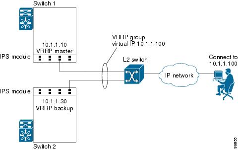
All members of the VRRP group (see Figure 42-4) must be IP storage Gigabit Ethernet ports. VRRP group members can be one or more of the following interfaces:
- One or more interfaces in the same IPS module or MPS-14/2 module
- Interfaces across IPS modules or MPS-14/2 modules in one switch
- Interfaces across IPS modules or MPS-14/2 modules in different switches
- Gigabit Ethernet subinterfaces
- Ethernet PortChannels and PortChannel subinterfaces
Note You can configure no more than seven VRRP groups, both IPv4 and IPv6, on a Gigabit Ethernet interface, including the main interface and all subinterfaces.
About Ethernet PortChannel Aggregation
Ethernet PortChannels refer to the aggregation of multiple physical Gigabit Ethernet interfaces into one logical Ethernet interface to provide link redundancy and, in some cases, higher aggregated bandwidth and load balancing.
An Ethernet switch connecting to the MDS switch Gigabit Ethernet port can implement load balancing based on the IP address, IP address and UDP/TCP port number, or MAC address. Due to the load balancing scheme, the data traffic from one TCP connection is always sent out on the same physical Gigabit Ethernet port of an Ethernet PortChannel. For the traffic coming to the MDS, an Ethernet switch can implement load balancing based on its IP address, its source-destination MAC address, or its IP address and port. The data traffic from one TCP connection always travels on the same physical links. To make use of both ports for the outgoing direction, multiple TCP connections are required.
All FCIP data traffic for one FCIP link is carried on one TCP connection. Consequently, the aggregated bandwidth is 1 Gbps for that FCIP link.
Note The Cisco Ethernet switch’s PortChannel should be configured as a static PortChannel, and not the default 802.3ad protocol.
Ethernet PortChannels can only aggregate two physical interfaces that are adjacent to each other on a given IPS module (see Figure 42-5).
Note PortChannel members must be one of these combinations: ports 1–2, ports 3–4, ports 5–6, or ports 7–8.
Figure 42-5 Ethernet PortChannel Scenario
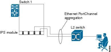
In Figure 42-5, Gigabit Ethernet ports 3 and 4 in slot 9 are aggregated into an Ethernet PortChannel. Ethernet PortChannels are not supported on MPS-14/2 modules and 9216i IPS modules.
Note PortChannel interfaces provide configuration options for both Gigabit Ethernet and Fibre Channel. However, based on the PortChannel membership, only Gigabit Ethernet parameters or Fibre Channel parameters are applicable.
CDP
The Cisco Discovery Protocol (CDP) is an advertisement protocol used by Cisco devices to advertise itself to other Cisco devices in the same network. CDP runs on the data link layer and is independent of Layer 3 protocols. CDP is supported on the management Ethernet interface on the supervisor module and the Gigabit Ethernet interfaces on the IPS and MPS-14/2 modules.
CDP version 1 (v1) and version 2 (v2) are supported in Cisco MDS 9000 Family switches. CDP packets with any other version number are silently discarded when received.
See the Cisco MDS 9000 Family NX-OS Fundamentals Configuration Guide.
Licensing Requirements for IP Storage
The following table shows the licensing requirements for this feature:
Guidelines and Limitations
Tip If IPv4-ACLs are already configured in a Gigabit Ethernet interface, you cannot add this interface to an Ethernet PortChannel group.
Follow these guidelines when configuring IPv4-ACLs for Gigabit Ethernet interfaces:
Note Other protocols such as User Datagram Protocol (UDP) and HTTP are not supported in Gigabit Ethernet interfaces. Applying an ACL that contains rules for these protocols to a Gigabit Ethernet interface is allowed but those rules have no effect.
- Apply IPv4-ACLs to the interface before you enable an interface. This ensures that the filters are in place before traffic starts flowing.
- Be aware of the following conditions:
– If you use the log-deny option, a maximum of 50 messages are logged per second.
– The established , precedence , and fragments options are ignored when you apply IPv4-ACLs (containing these options) to Gigabit Ethernet interfaces.
– If an IPv4-ACL rule applies to a preexisting TCP connection, that rule is ignored. For example if there is an existing TCP connection between A and B, and an IPv4-ACL specifies dropping all packets whose source is A and destination is B is subsequently applied, it will have no effect.
Default Settings
Table 42-2 lists the default settings for IP storage services parameters.
Configuring IP Storage
This section includes the following topics:
- Configuring IPS Core Dumps
- Configuring VRRP for Gigabit Ethernet Interfaces
- Configuring Ethernet PortChannels
Configuring IPS Core Dumps
To configure IPS core dumps on the IPS module, follow these steps:
Configures a dump of the full core generation for all IPS modules in the switch. |
||
Configures a dump of the partial core (default) generation for the IPS module in slot 9. |
To configure the Gigabit Ethernet interface for the scenario in Figure 42-3, follow these steps:
Step 1 From Cisco DCNM-SAN, choose Switches > Interfaces > Gigabit Ethernet in the Physical Attributes pane. You see the Gigabit Ethernet configuration in the Information pane.
From Device Manager, right-click the Gigabit Ethernet port that you want to configure and choose Configure.... You see the Gigabit Ethernet configuration dialog box.
Step 2 Click the General tab in Cisco DCNM-SAN, or click the GigE tab in Device Manager to display the general configuration options for the interface.
Step 3 Set the description and MTU value for the interface. The valid value for the MTU field can be a number in the range from 576 to 9000.
Step 4 Set Admin up or down and check the CDP check box if you want this interface to participate in CDP.
Step 5 Set IpAddress/Mask with the IP address and subnet mask for this interface.
Step 6 From Cisco DCNM-SAN, click the Apply Changes icon to save these changes, or click the Undo Changes icon to discard changes.
From Device Manager, click Apply to save these changes, or click Close to discard changes and close the Gigabit Ethernet configuration dialog box.
Configuring VRRP for Gigabit Ethernet Interfaces
To configure VRRP for Gigabit Ethernet interfaces using IPv4, follow these steps:
To configure VRRP for Gigabit Ethernet interfaces using IPv6, follow these steps:
Note If you configure secondary VRRP IPv6 addresses on an IPFC VSAN interface, before a downgrading to a release prior to Cisco Release 3.0(1), you must remove the secondary VRRP IPv6 addresses. This is required only when you configure IPv6 addresses.
Note The VRRP preempt option is not supported on IPS Gigabit Ethernet interfaces. However, if the virtual IPv4 IP address is also the IPv4 IP address for the interface, then preemption is implicitly applied.
Note If you configure secondary VRRP IPv6 addresses on an IPFC VSAN interface, before a downgrading to a release prior to Cisco Release 3.0(1), you must remove the secondary VRRP IPv6 addresses. This is required only when you configure IPv6 addresses.
Configuring Ethernet PortChannels
The PortChannel configuration specified in the Interfaces Configuration Guide, Cisco DCNM for SANCisco MDS 9000 Family NX-OS Interfaces Configuration Guide also applies to Ethernet PortChannel configurations.
To configure Ethernet PortChannels, follow these steps:
Verifying IP Storage Configuration
To display IP storage configuration information, perform one of the following tasks:
This section includes the following topics:
- Verifying Module Status
- Displaying Gigabit Ethernet Interface Statistics
- Displaying Ethernet MAC Statistics
- Displaying DMA-Bridge Statistics
- Displaying TCP Statistics
Verifying Module Status
After inserting the module, verify the status of the module using the show module command:
To verify the status of the module, follow these steps:
Step 1 Select a switch in the Fabric pane.
Step 2 Open the Switches folder and select Hardware in the Physical Attributes pane.
You see the status for all modules in the switch in the Information pane.
Displaying Gigabit Ethernet Interface Statistics
Use the show interface gigabitethernet command on each switch to verify that the interfaces are up and functioning as desired. See Example 42-1 and Example 42-2.
Displaying Ethernet MAC Statistics
The show ips stats mac interface gigabitethernet command takes the main Gigabit Ethernet interface as a parameter and returns Ethernet statistics for that interface. See Example 42-3.
Note Use the physical interface, not the subinterface, to display Ethernet MAC statistics.
Displaying DMA-Bridge Statistics
You can display direct memory access (DMA) device statistics using the show ips stats dma-bridge interface gigabitethernet command. This command takes the main Gigabit Ethernet interface as a parameter and returns DMA bridge statistics for that interface. See Example 42-4.
Note Use the physical interface, not the subinterface, to display DMA-bridge statistics.
Example 42-4 Displays DMA-Bridge Statistics
This output shows all Fibre Channel frames that ingress or egress from the Gigabit Ethernet port.
Displaying TCP Statistics
Use the show ips stats tcp interface gigabitethernet to display and verify TCP statistics. This command takes the main Ethernet interface as a parameter, and shows TCP stats along with the connection list and TCP state. The detail option shows all information maintained by the interface. See Example 42-5 and Example 42-6.
Example 42-5 Displays TCP Statistics
Example 42-6 Displays Detailed TCP Statistics
Use the show ips stats icmp interface gigabitethernet to display and verify IP statistics. This command takes the main Ethernet interface as a parameter and returns the ICMP statistics for that interface. See Example 42-7.
Field Descriptions for IP Storage
This section describes the following field descriptions.
 Feedback