- Device Manager Help
- Configuring Cisco DCNM-SAN Server
- Configuring Authentication in Cisco DCNM-SAN
- Configuring Cisco DCNM-SAN Client
- Device Manager
- Configuring Performance Manager
- Configuring High Availability
- Configuring Trunking
- Configuring PortChannels
- Configuring N Port Virtualization
- Configuring Interfaces
- Configuration of Fibre Channel Interfaces
- Using the CFS Infrastructure
- Configuring SNMP
- Configuring Domain Parameters
- Configuring and Managing Zones
- Configuring FCoE
- Configuring Dense Wavelength Division Multiplexing
- Configuring and Managing VSANs
- Discovering SCSI Targets
- Configuring SAN Device Virtualization
- Configuring Fibre Channel Routing Services and Protocols
- Managing FLOGI, Name Server, FDMI, and RSCN Databases
- Configuring FICON
- Creating Dynamic VSANs
- Distributing Device Alias Services
- Configuring Advanced Fabric Features
- Configuring Users and Common Role
- Configuring Security Features on an External AAA Server
- Configuring Certificate Authorities and Digital Certificates
- Configuring FC-SP and DHCHAP
- Configuring Cisco TrustSec Fibre Channel Link Encryption
- Configuring FIPS
- Configuring IPv4 and IPv6 Access Control Lists
- Configuring IPsec Network Security
- Configuring Port Security
- Configuring Fabric Binding
- Configuring FCIP
- Configuring the SAN Extension Tuner
- Configuring iSCSI
- Configuring IP Services
- Configuring IP Storage
- Configuring IPv4 for Gigabit Ethernet Interfaces
- Configuring IPv6 for Gigabit Ethernet Interfaces
- Configuring SCSI Flow Services
- Configuring SCSI Flow Statistics
- Configuring Fibre Channel Write Acceleration
- Monitoring the Network
- Monitoring Performance
- Configuring Call Home
- Configuring System Message Logging
- Scheduling Maintenance Jobs
- Configuring RMON
- Configuring Fabric Configuration Server
- Monitoring Network Traffic Using SPAN
- Monitoring System Processes and Logs
- Configuring QoS
- Configuring Port Tracking
- Configuring FlexAttach Virtual pWWN
- Configuring Interface Buffers
- Verifying Ethernet Interfaces
- Information About Zoning
- Zone Implementation
- About the Edit Local Full Zone Database Tool
- About Zone Sets
- About Zone Set Creation
- About the Default Zone
- About FC Alias Creation
- Zone Enforcement
- Zone Set Distribution
- About Recovering from Link Isolation
- Zone Set Duplication
- About Backing Up and Restoring Zones
- About Zone-Based Traffic Priority
- About Broadcast Zoning
- About LUN Zoning
- About Read-Only Zones
- About Enhanced Zoning
- Merging the Database
- Smart Zoning
- Licensing Requirements for Zoning
- Guidelines and Limitations
- Default Settings
- Configuring Zones
- Configuring Zone Sets
- Activating a Zone Set
- Deactivating a Zone Set
- Displaying Zone Membership Information
- Configuring the Default Zone Access Permission
- Creating FC Aliases
- Adding Members to Aliases
- Converting Zone Members to pWWN-based Members
- Creating Zone Sets and Adding Member Zones
- Filtering Zones, Zone Sets, and Device Aliases Based on Name
- Adding Multiple Zones to Multiple Zone Sets
- Enabling Full Zone Set Distribution
- Enabling a One-Time Distribution
- Importing and Exporting Zone Sets
- Copying Zone Sets
- Backing Up Zones
- Restoring Zones
- Renaming Zones, Zone Sets, and Aliases
- Cloning Zones, Zone Sets, FC Aliases, and Zone Attribute Groups
- Migrating a Non-MDS Database
- Clearing the Zone Server Database
- Configuring Zone-Based Traffic Priority
- Configuring Default Zone QoS Priority Attributes
- Configuring the Default Zone Policy
- Configuring Smart Zoning
- Configuring Global Zone Policies
- Configuring Broadcast Zoning
- Configuring a LUN-Based Zone
- Assigning LUNs to Storage Subsystems
- Configuring Read-Only Zones
- Changing from Basic Zoning to Enhanced Zoning
- Changing from Enhanced Zoning to Basic Zoning
- Enabling Enhanced Zoning
- Modifying the Zone Database
- Releasing Zone Database Locks
- Creating Attribute Groups
- Analyzing a Zone Merge
- Configuring Zone Merge Control Policies
- Preventing Zones From Flooding FC2 Buffers
- Permitting or Denying Traffic in the Default Zone
- Broadcasting a Zone
- Configuring System Default Zoning Settings
- Configuring Zone Generic Service Permission Settings
- Compacting the Zone Database for Downgrading
- Verifying Zone Configuration
- Configuration Examples for Zoning
- Field Descriptions for Zones
- Additional References
Configuring and Managing Zones
Zoning enables you to set up access control between storage devices or user groups. If you have administrator privileges in your fabric, you can create zones to increase network security and to prevent data loss or corruption. Zoning is enforced by examining the source-destination ID field.
Advanced zoning capabilities specified in the FC-GS-4 and FC-SW-3 standards are provided. You can use either the existing basic zoning capabilities or the advanced, standards-compliant zoning capabilities.
For information about design parameters and best practices to Migrate a SAN from a Heterogeneous Environment to a Cisco MDS 9000 Family SAN, refer to Migrate a SAN from a Heterogeneous Environment to a Cisco MDS 9000 Family SAN .
Information About Zoning
Zoning has the following features:
– Members in a zone can access each other; members in different zones cannot access each other.
– If zoning is not activated, all devices are members of the default zone.
– If zoning is activated, any device that is not in an active zone (a zone that is part of an active zone set) is a member of the default zone.
– Devices can belong to more than one zone.
– A physical fabric can have a maximum of 16,000 members. This includes all VSANs in the fabric.
– A zone set can be activated or deactivated as a single entity across all switches in the fabric.
– Only one zone set can be activated at any time.
– A zone can be a member of more than one zone set.
– A zone switch can have a maximum of 500 zone sets.
– When you activate a zone (from any switch), all switches in the fabric receive the active zone set. Additionally, full zone sets are distributed to all switches in the fabric, if this feature is enabled in the source switch.
– If a new switch is added to an existing fabric, zone sets are acquired by the new switch.
- Zone changes can be configured nondisruptively. New zones and zone sets can be activated without interrupting traffic on unaffected ports or devices.
- Zone membership criteria is based mainly on WWNs or FC IDs.
– Port world wide name (pWWN)—Specifies the pWWN of an N port attached to the switch as a member of the zone.
– Fabric pWWN—Specifies the WWN of the fabric port (switch port’s WWN). This membership is also referred to as port-based zoning.
– FC ID—Specifies the FC ID of an N port attached to the switch as a member of the zone.
– Interface and switch WWN (sWWN)—Specifies the interface of a switch identified by the sWWN. This membership is also referred to as interface-based zoning.
– Interface and domain ID—Specifies the interface of a switch identified by the domain ID.
– Domain ID and port number—Specifies the domain ID of an MDS domain and additionally specifies a port belonging to a non-Cisco switch.
– IPv4 address—Specifies the IPv4 address (and optionally the subnet mask) of an attached device.
– IPv6 address—The IPv6 address of an attached device in 128 bits in colon(:)-separated hexadecimal format.
- Default zone membership includes all ports or WWNs that do not have a specific membership association. Access between default zone members is controlled by the default zone policy.
- You can configure up to 8000 zones per VSAN and a maximum of 8000 zones for all VSANs on the switch.
This section includes the following topics:
- Zone Implementation
- About the Edit Local Full Zone Database Tool
- About Zone Sets
- About Zone Set Creation
- About the Default Zone
- About FC Alias Creation
- Zone Enforcement
- Zone Set Distribution
- About Recovering from Link Isolation
- Zone Set Duplication
- About Backing Up and Restoring Zones
- About Zone-Based Traffic Priority
- About Broadcast Zoning
- About LUN Zoning
- About Read-Only Zones
- About Enhanced Zoning
- Merging the Database
- Smart Zoning
Zone Implementation
All switches in the Cisco MDS 9000 Family automatically support the following basic zone features (no additional configuration is required):
- Zones are contained in a VSAN.
- Hard zoning cannot be disabled.
- Name server queries are soft-zoned.
- Only active zone sets are distributed.
- Unzoned devices cannot access each other.
- A zone or zone set with the same name can exist in each VSAN.
- Each VSAN has a full database and an active database.
- Active zone sets cannot be changed, without activating a full zone database.
- Active zone sets are preserved across switch reboots.
- Changes to the full database must be explicitly saved.
- Zone reactivation (a zone set is active and you activate another zone set) does not disrupt existing traffic.
If required, you can additionally configure the following zone features:
- Propagate full zone sets to all switches on a per VSAN basis.
- Change the default policy for unzoned members.
- Interoperate with other vendors by configuring a VSAN in the interop mode. You can also configure one VSAN in the interop mode and another VSAN in the basic mode in the same switch without disrupting each other.
- Bring E ports out of isolation.
About the Edit Local Full Zone Database Tool
You can use the Edit Full Zone Database Tool to complete the following tasks:
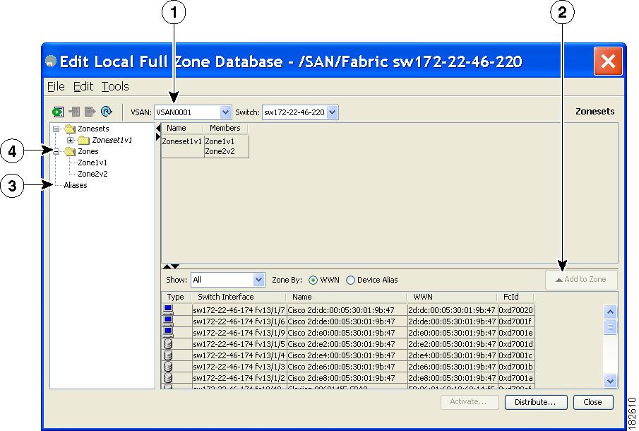
- You can display information by VSAN by using the pull-down menu without having to get out of the screen, selecting a VSAN, and re-entering.
- You can use the Add to zone or alias button to move devices up or down by alias or by zone.
- You can add zoning characteristics based on alias in different folders.
- You can triple-click to rename zone sets, zones, or aliases in the tree.
The Edit Local Full Zone Database tool allows you to zone across multiple switches and all zoning features are available through the Edit Local Full Zone Database dialog box (see Figure 16-1).
Figure 16-1 Edit Local Full Zone Database Dialog Box


Note The Device Alias radio button is visible only if device alias is in enhanced mode. For more information, see “Creating Device Aliases” section.
About Zone Sets
Zones provide a method for specifying access control. Zone sets are a grouping of zones to enforce access control in the fabric.
Zone sets are configured with the names of the member zones and the VSAN (if the zone set is in a configured VSAN).
Zone Set Distribution —You can distribute full zone sets using one of two methods: one-time distribution or full zone set distribution.
Zone Set Duplication —You can make a copy of a zone set and then edit it without altering the original zone set. You can copy an active zone set from the bootflash: directory, volatile: directory, or slot0, to one of the following areas:
The active zone set is not part of the full zone set. You cannot make changes to an existing zone set and activate it, if the full zone set is lost or is not propagated.
About Zone Set Creation
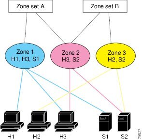
In Figure 16-2, two separate sets are created, each with its own membership hierarchy and zone members.
Figure 16-2 Hierarchy of Zone Sets, Zones, and Zone Members

Either zone set A or zone set B can be activated (but not together).

Tip Zone sets are configured with the names of the member zones and the VSAN (if the zone set is in a configured VSAN).
About the Default Zone
Each member of a fabric (in effect a device attached to an Nx port) can belong to any zone. If a member is not part of any active zone, it is considered to be part of the default zone. Therefore, if no zone set is active in the fabric, all devices are considered to be in the default zone. Even though a member can belong to multiple zones, a member that is part of the default zone cannot be part of any other zone. The switch determines whether a port is a member of the default zone when the attached port comes up.

Note Unlike configured zones, default zone information is not distributed to the other switches in the fabric.
Traffic can either be permitted or denied among members of the default zone. This information is not distributed to all switches; it must be configured in each switch.

Note When the switch is initialized for the first time, no zones are configured and all members are considered to be part of the default zone. Members are not permitted to talk to each other.
Configure the default zone policy on each switch in the fabric. If you change the default zone policy on one switch in a fabric, be sure to change it on all the other switches in the fabric.

Note The default settings for default zone configurations can be changed.
The default zone members are explicitly listed when the default policy is configured as permit or when a zone set is active. When the default policy is configured as deny, the members of this zone are not explicitly enumerated when you issue the show zoneset active command view the active zone set.

Note The current default zoning policy in both the switches is deny. In the Cisco MDS 9222i Switch, the active zone set is coco_isola_zoneset. In the Cisco MDS 9513 Switch, there is no active zone set. However, because the default zoning policy is deny, the hidden active zone set is d__efault__cfg which causes zone merge to fail. The behavior is same between two Brocade switches.
You can change the default zone policy for any VSAN by choosing VSANxx > Default Zone from the DCNM-SAN menu tree and clicking the Policies tab. It is recommended that you establish connectivity among devices by assigning them to a nondefault zone.
About FC Alias Creation
You can assign an alias name and configure an alias member using the following values:
- pWWN—The WWN of the N or NL port is in hex format (for example, 10:00:00:23:45:67:89:ab).
- fWWN—The WWN of the fabric port name is in hex format (for example, 10:00:00:23:45:67:89:ab).
- FC ID—The N port ID is in 0xhhhhhh format (for example, 0xce00d1).
- Domain ID—The domain ID is an integer from 1 to 239. A mandatory port number of a non-Cisco switch is required to complete this membership configuration.
- IPv4 address—The IPv4 address of an attached device is in 32 bits in dotted decimal format along with an optional subnet mask. If a mask is specified, any device within the subnet becomes a member of the specified zone.
- IPv6 address—The IPv6 address of an attached device is in 128 bits in colon- (:) separated) hexadecimal format.
- Interface—Interface-based zoning is similar to port-based zoning because the switch interface is used to configure the zone. You can specify a switch interface as a zone member for both local and remote switches. To specify a remote switch, enter the remote switch WWN (sWWN) or the domain ID in the particular VSAN.

Tip The Cisco NX-OS software supports a maximum of 2048 aliases per VSAN.
Zone Enforcement
Zoning can be enforced in two ways: soft and hard. Each end device (N port or NL port) discovers other devices in the fabric by querying the name server. When a device logs in to the name server, the name server returns the list of other devices that can be accessed by the querying device. If an Nx port does not know about the FC IDs of other devices outside its zone, it cannot access those devices.
In soft zoning, zoning restrictions are applied only during interaction between the name server and the end device. If an end device somehow knows the FC ID of a device outside its zone, it can access that device.
Hard zoning is enforced by the hardware on each frame sent by an Nx port. As frames enter the switch, source-destination IDs are compared with permitted combinations to allow the frame at wirespeed. Hard zoning is applied to all forms of zoning.

Note Hard zoning enforces zoning restrictions on every frame, and prevents unauthorized access.
Switches in the Cisco MDS 9000 Family support both hard and soft zoning.
Zone Set Distribution
You can distribute full zone sets using one of two methods: one-time distribution at the EXEC mode level or full zone set distributionat the configuration mode level.
You can distribute full zone sets using one of two methods: one-time distribution or full zone set distribution.
Table 16-1 lists the differences between these distribution methods.
About Recovering from Link Isolation
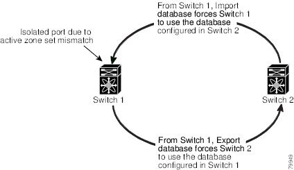
When two switches in a fabric are merged using a TE or E port, these TE and E ports may become isolated when the active zone set databases are different between the two switches or fabrics. When a TE port or an E port become isolated, you can recover that port from its isolated state using one of three options:
- Import the neighboring switch's active zone set database and replace the current active zone set (see Figure 16-3).
- Export the current database to the neighboring switch.
- Manually resolve the conflict by editing the full zone set, activating the corrected zone set, and then bringing up the link.
Figure 16-3 Importing and Exporting the Database

Zone Set Duplication
You can make a copy and then edit it without altering the existing active zone set. You can copy an active zone set from the bootflash: directory, volatile: directory, or slot0, to one of the following areas:
The active zone set is not part of the full zone set. You cannot make changes to an existing zone set and activate it, if the full zone set is lost or is not propagated.

About Backing Up and Restoring Zones
You can back up the zone configuration to a workstation using TFTP. This zone backup file can then be used to restore the zone configuration on a switch. Restoring the zone configuration overwrites any existing zone configuration on a switch.
About Zone-Based Traffic Priority
The zoning feature provides an additional segregation method to prioritize select zones in a fabric and set up access control between devices. Using this feature, you can configure the quality of service (QoS) priority as a zone attribute. You can assign the QoS traffic priority attribute to be high, medium, or low. By default, zones with no specified priority are implicitly assigned a low priority. Refer to the Cisco MDS 9000 NX-OS Family Quality of Service Configuration Guide for more information.
To use this feature, you need to obtain the ENTERPRISE_PKG license (refer to the Cisco NX-OS Family Licensing Guide ) and you must enable QoS in the switch (refer to the Cisco MDS 9000 Family NX-OS Quality of Service Configuration Guide ).
This feature allows SAN administrators to configure QoS using a familiar data flow identification paradigm. You can configure this attribute on a zone-wide basis rather than between zone members.

About Broadcast Zoning

Note Broadcast zoning is not supported on the Cisco Fabric Switch for HP c-Class BladeSystem and the Cisco Fabric Switch for IBM BladeCenter.
You can configure broadcast frames in the basic zoning mode. By default, broadcast zoning is disabled and broadcast frames are sent to all Nx ports in the VSAN. When enabled, broadcast frames are only sent to Nx ports in the same zone, or zones, as the sender. Enable broadcast zoning when a host or storage device uses this feature.
Table 16-2 identifies the rules for the delivery of broadcast frames.

Tip If any NL port attached to an FL port shares a broadcast zone with the source of the broadcast frame, then the frames are broadcast to all devices in the loop.

About LUN Zoning
Logical unit number (LUN) zoning is a feature specific to switches in the Cisco MDS 9000 Family.

A storage device can have multiple LUNs behind it. If the device port is part of a zone, a member of the zone can access any LUN in the device. With LUN zoning, you can restrict access to specific LUNs associated with a device.

Note When LUN 0 is not included within a zone, control traffic to LUN 0 (for example, REPORT_LUNS, INQUIRY) is supported, but data traffic to LUN 0 (for example, READ, WRITE) is denied.
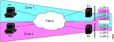
- Host H1 can access LUN 2 in S1 and LUN 0 in S2. It cannot access any other LUNs in S1 or S2.
- Host H2 can access LUNs 1 and 3 in S1 and only LUN 1 in S2. It cannot access any other LUNs in S1 or S2.

Note Unzoned LUNs automatically become members of the default zone.
shows a LUN-based zone example.

About Read-Only Zones
By default, an initiator has both read and write access to the target's media when they are members of the same Fibre Channel zone. The read-only zone feature allows members to have only read access to the media within a read-only Fibre Channel zone.
You can also configure LUN zones as read-only zones. Any zone can be identified as a read-only zone. By default all zones have read-write permission unless explicitly configured as a read-only zone.
About Enhanced Zoning
Table 16-3 lists the advantages of the enhanced zoning feature in all switches in the Cisco MDS 9000 Family.
Merging the Database
The merge behavior depends on the fabric-wide merge control setting:
- Restrict—If the two databases are not identical, the ISLs between the switches are isolated.
- Allow—The two databases are merged using the merge rules specified in Table 16-4 .
|
The databases contain zone sets with the same name1 but different zones, aliases, and attributes groups. |
|||
|
The databases contains a zone, zone alias, or zone attribute group object with same name 1 but different members. |
|||
The adjacent database information populates the local database. |
|||
The local database information populates the adjacent database. |
|||
|
1.In the enhanced zoning mode, the active zone set does not have a name in interop mode 1. The zone set names are only present for full zone sets. |
 Feedback