- Device Manager Help
- Configuring Cisco DCNM-SAN Server
- Configuring Authentication in Cisco DCNM-SAN
- Configuring Cisco DCNM-SAN Client
- Device Manager
- Configuring Performance Manager
- Configuring High Availability
- Configuring Trunking
- Configuring PortChannels
- Configuring N Port Virtualization
- Configuring Interfaces
- Configuration of Fibre Channel Interfaces
- Using the CFS Infrastructure
- Configuring SNMP
- Configuring Domain Parameters
- Configuring and Managing Zones
- Configuring FCoE
- Configuring Dense Wavelength Division Multiplexing
- Configuring and Managing VSANs
- Discovering SCSI Targets
- Configuring SAN Device Virtualization
- Configuring Fibre Channel Routing Services and Protocols
- Managing FLOGI, Name Server, FDMI, and RSCN Databases
- Configuring FICON
- Creating Dynamic VSANs
- Distributing Device Alias Services
- Configuring Advanced Fabric Features
- Configuring Users and Common Role
- Configuring Security Features on an External AAA Server
- Configuring Certificate Authorities and Digital Certificates
- Configuring FC-SP and DHCHAP
- Configuring Cisco TrustSec Fibre Channel Link Encryption
- Configuring FIPS
- Configuring IPv4 and IPv6 Access Control Lists
- Configuring IPsec Network Security
- Configuring Port Security
- Configuring Fabric Binding
- Configuring FCIP
- Configuring the SAN Extension Tuner
- Configuring iSCSI
- Configuring IP Services
- Configuring IP Storage
- Configuring IPv4 for Gigabit Ethernet Interfaces
- Configuring IPv6 for Gigabit Ethernet Interfaces
- Configuring SCSI Flow Services
- Configuring SCSI Flow Statistics
- Configuring Fibre Channel Write Acceleration
- Monitoring the Network
- Monitoring Performance
- Configuring Call Home
- Configuring System Message Logging
- Scheduling Maintenance Jobs
- Configuring RMON
- Configuring Fabric Configuration Server
- Monitoring Network Traffic Using SPAN
- Monitoring System Processes and Logs
- Configuring QoS
- Configuring Port Tracking
- Configuring FlexAttach Virtual pWWN
- Configuring Interface Buffers
- Verifying Ethernet Interfaces
Information About N Port Virtualization
This section includes the following topics:
- NPV Overview
- N Port Identifier Virtualization
- N Port Virtualization
- NPV Mode
- NP Ports
- NP Links
- Default Port Numbers
- NPV CFS Distribution over IP
- NPV Traffic Management
- Multiple VSAN Support
NPV Overview
N port virtualization (NPV) reduces the number of Fibre Channel domain IDs in SANs. Switches operating in the NPV mode do not join a fabric. They pass traffic between NPV core switch links and end devices, which eliminates the domain IDs for these edge switches.
NPV is supported by the following Cisco MDS 9000 switches and Cisco Nexus 5000 Series switches only:
- Cisco MDS 9124 Multilayer Fabric Switch
- Cisco MDS 9134 Fabric Switch
- Cisco MDS 9148 Multilayer Fabric Switch
- Cisco Fabric Switch for HP c-Class BladeSystem
- Cisco Fabric Switch for IBM BladeCenter
- Cisco Nexus 5000 Series switches

Note NPV is available on these switches only while in NPV mode; if in switch mode, NPV is not available.
N Port Identifier Virtualization
N port identifier virtualization (NPIV) provides a means to assign multiple FC IDs to a single N port. This feature allows multiple applications on the N port to use different identifiers and allows access control, zoning, and port security to be implemented at the application level.
Figure 10-1 shows an example application using NPIV.
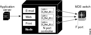
You must globally enable NPIV for all VSANs on the MDS switch to allow the NPIV-enabled applications to use multiple N port identifiers.
Note All of the N port identifiers are allocated in the same VSAN.
N Port Virtualization
Typically, Fibre Channel networks are deployed using a core-edge model with a large number of fabric switches connected to edge devices. Such a model is cost-effective because the per port cost for director class switches is much higher than that of fabric switches. However, as the number of ports in the fabric increases, the number of switches deployed also increases, and you can end up with a significant increase in the number of domain IDs (the maximum number supported is 239). This challenge becomes even more difficult when additional blade chassis are deployed in Fibre Channel networks.
NPV addresses the increase in the number of domain IDs needed to deploy a large number of the ports by making a fabric or blade switch appear as a host to the core Fibre Channel switch, and as a Fibre Channel switch to the servers in the fabric or blade switch. NPV aggregates multiple locally connected N ports into one or more external NP links, which shares the domain ID of the NPV core switch among multiple NPV switches. NPV also allows multiple devices to attach to same port on the NPV core switch, which reduces the need for more ports on the core.
Figure 10-2 Cisco NPV Fabric Configuration
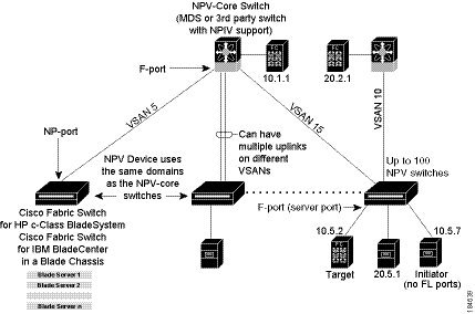
While NPV is similar to N port identifier virtualization (NPIV), it does not offer exactly the same functionality. NPIV provides a means to assign multiple FC IDs to a single N port, and allows multiple applications on the N port to use different identifiers. NPIV also allows access control, zoning, and port security to be implemented at the application level. NPV makes use of NPIV to get multiple FCIDs allocated from the core switch on the NP port.
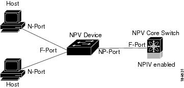
Figure 10-3 shows a more granular view of an NPV configuration at the interface level.
Figure 10-3 Cisco NPV Configuration–Interface View
NPV Mode
A switch is in NPV mode after a user has enabled NPV and the switch has successfully rebooted. NPV mode applies to an entire switch. All end devices connected to a switch that is in NPV mode must log in as an N port to use this feature (loop-attached devices are not supported). All links from the edge switches (in NPV mode) to the NPV core switches are established as NP ports (not E ports), which are used for typical interswitch links. NPIV is used by the switches in NPV mode to log in to multiple end devices that share a link to the NPV core switch.
Note In-order data delivery is not required in NPV mode because the exchange between two end devices always takes the same uplink to the core from the NPV device. For traffic beyond the NPV device, core switches will enforce in-order delivery if needed and/or configured.
After entering NPV mode, only the following commands are available:
NP Ports
An NP port (proxy N port) is a port on a device that is in NPV mode and connected to the NPV core switch using an F port. NP ports behave like N ports except that in addition to providing N port behavior, they also function as proxies for multiple, physical N ports.
Note A Cisco Nexus 5000 Series switch in NPV mode that runs Cisco NX-OS Release 4.2(1) or later releases supports trunking F port mode on NP ports. You can enable either, or both, VSAN trunking and an F port on an NP port.
NP Links
An NP link is basically an NPIV uplink to a specific end device. NP links are established when the uplink to the NPV core switch comes up; the links are terminated when the uplink goes down. Once the uplink is established, the NPV switch performs an internal FLOGI to the NPV core switch, and then (if the FLOGI is successful) registers itself with the NPV core switch’s name server. Subsequent FLOGIs from end devices in this NP link are converted to FDISCs. For more details refer to the “Internal FLOGI Parameters” section.
Server links are uniformly distributed across the NP links. All the end devices behind a server link will be mapped to only one NP link.
Internal FLOGI Parameters
When an NP port comes up, the NPV device first logs itself in to the NPV core switch and sends a FLOGI request that includes the following parameters:
- The fWWN (fabric port WWN) of the NP port used as the pWWN in the internal login.
- The VSAN-based sWWN (switch WWN) of the NPV device used as nWWN (node WWN) in the internal FLOGI.
After completing its FLOGI request, the NPV device registers itself with the fabric name server using the following additional parameters:
- Switch name and interface name (for example, fc1/4) of the NP port is embedded in the symbolic port name in the name server registration of the NPV device itself.
- The IP address of the NPV device is registered as the IP address in the name server registration of the NPV device.
Note The BB_SCN of internal FLOGIs on NP ports is always set to zero. The BB_SCN is supported at the F-port of the NPV device.
Figure 10-4 shows the internal FLOGI flows between an NPV core switch and an NPV device.
Figure 10-4 Internal FLOGI Flows
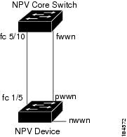
Table 10-1 identifies the internal FLOGI parameters that appear in Figure 10-4.
The switch name and NP port interface string. Note If there is no switch name available, then the output will display “switch.” For example, switch: fc1/5. |
|
Although fWWN-based zoning is supported for NPV devices, it is not recommended because:
- Zoning is not enforced at the NPV device (rather, it is enforced on the NPV core switch).
- Multiple devices behind an NPV device log in via the same F port on the core (they use same fWWN and cannot be separated into different zones).
- The same device might log in using different fWWNs on the core switch (depending on the NPV link it uses) and may need to be zoned using different fWWNs.
Default Port Numbers
Port numbers on NPV-enabled switches will vary depending on the switch model. For details about port numbers for NPV-eligible switches, see the Cisco NX-OS Family Licensing Guide .
NPV CFS Distribution over IP
NPV devices use only IP as the transport medium. CFS uses multicast forwarding for CFS distribution. NPV devices do not have ISL connectivity and FC domain. To use CFS over IP, multicast forwarding has to be enabled on the Ethernet IP switches all along the network that physically connects the NPV switch. You can also manually configure the static IP peers for CFS distribution over IP on NPV-enabled switches. For more information, see the Cisco MDS 9000 Family NX-OS System Management Configuration Guide .
Auto
Before Cisco MDS SAN-OS Release 3.3(1a), NPV supported automatic selection of external links. When a server interface is brought up, an external interface with the minimum load is selected from the available links. There is no manual selection on the server interfaces using the external links. Also, when a new external interface was brought up, the existing load was not distributed automatically to the newly available external interface. This newly brought up interface is used only by the server interfaces that come up after this interface.
Traffic Map
As in Cisco MDS SAN-OS Release 3.3(1a) and NX-OS Release 4.1(1a), NPV supports traffic management by allowing you to select and configure the external interfaces that the server uses to connect to the core switches.
Note When the NPV traffic management is configured, the server uses only the configured external interfaces. Any other available external interface will not be used.
The NPV traffic management feature provides the following benefits:
- Facilitates traffic engineering by providing dedicated external interfaces for the servers connected to NPV.
- Uses the shortest path by selecting external interfaces per server interface.
- Uses the persistent FC ID feature by providing the same traffic path after a link break, or reboot of the NPV or core switch.
- Balances the load by allowing the user to evenly distribute the load across external interfaces.
Disruptive
Disruptive load balance works independent of automatic selection of interfaces and a configured traffic map of external interfaces. This feature forces reinitialization of the server interfaces to achieve load balance when this feature is enabled and whenever a new external interface comes up. To avoid flapping the server interfaces too often, enable this feature once and then disable it whenever the needed load balance is achieved.
If disruptive load balance is not enabled, you need to manually flap the server interface to move some of the load to a new external interface.
Guidelines and Limitations
This section includes the guidelines and limitations for this feature:
- NPV Guidelines and Requirements
- NPV Traffic Management Guidelines
- DPVM Configuration Guidelines
- NPV and Port Security Configuration Guidelines
NPV Guidelines and Requirements
Following are recommended guidelines and requirements when deploying NPV:
- NPV core switches must support NPIV.
- You can have up to 100 NPV devices.
- Nondisruptive upgrades are supported. See the Cisco MDS 9000 Family NX-OS Fundamentals Configuration Guide .
- Port tracking is supported. See the Cisco MDS 9000 Family NX-OS Security Configuration Guide .
- You can configure zoning for end devices that are connected to NPV devices using all available member types on the NPV core switch. If fWWN, sWWN, domain, or port-based zoning is used, then fWWN, sWWN or the domain/port of the NPV core switch should be used.
- Port security is supported on the NPV core switch for devices logged in via NPV.
- NPV uses a load-balancing algorithm to automatically assign end devices in a VSAN to one of the NPV core switch links (in the same VSAN) upon initial login. If there are multiple NPV core switch links in the same VSAN, then you cannot assign a specific one to an end device.
- Both servers and targets can be connected to an NPV device.
- Remote SPAN is not supported.
- Local switching is not supported; all traffic is switched using the NPV core switch.
- NPV devices can connect to multiple NPV core switches. In other words, different NP ports can be connected to different NPV core switches.
- NPV supports NPIV-capable module servers (nested NPIV).
- Only F, NP, and SD ports are supported in NPV mode.
- In the case of servers that are booted over the SAN with NPV, if an NPV link failover occurs, servers will lose access to their boot LUN temporarily.
- NPV switches do not recognize the BB_SCN configuration on the xNP ports because of interoperability issues with the third-party core switches.
NPV Traffic Management Guidelines
When deploying NPV traffic management, follow these guidelines:
- Use NPV traffic management only when the automatic traffic engineering by the NPV device is not sufficient for the network requirements.
- Do not configure traffic maps for all the servers. For non-configured servers, NPV will use automatic traffic engineering.
- Configure the Persistent FC ID on the core switch. Traffic engineering directs the associated server interface to external interfaces that lead to the same core switch. The server will be assigned the same FC ID for every log in. This guideline is not applicable if a 91x4 switch is used as the core switch.
- Server interfaces configured to a set of external interfaces cannot use any other available external interfaces, even if the configured interfaces are not available.
- Do not configure disruptive load balancing because this involves moving a device from one external interface to another interface. Moving the device between external interfaces requires NPV relogin to the core switch through F port leading to traffic disruption.
- Link a set of servers to a core switch by configuring the server to a set of external interfaces that are linked to the core switch.
DPVM Configuration Guidelines
When NPV is enabled, the following requirements must be met before you configure DPVM on the NPV core switch:
- You must explicitly configure the WWN of the internal FLOGI in DPVM. If DPVM is configured on the NPV core switch for an end device that is connected to the NPV device, then that end device must be configured to be in the same VSAN. Logins from a device connected to an NPV device will fail if the device is configured to be in a different VSAN. To avoid VSAN mismatches, ensure that the internal FLOGI VSAN matches the port VSAN of the NP port.
- The first login from an NP port determines the VSAN of that port. If DPVM is configured for this first login, which is the internal login of the NPV device, then the NPV core switch’s VSAN F port is located in that VSAN. Otherwise, the port VSAN remains unchanged.
For details about DPVM configuration, see the Cisco MDS 9000 Family NX-OS Fabric Configuration Guide .
NPV and Port Security Configuration Guidelines
Port security is enabled on the NPV core switch on a per interface basis. To enable port security on the NPV core switch for devices logging in via NPV, you must adhere to the following requirements:
- The internal FLOGI must be in the port security database so that, the port on the NPV core switch will allow communications and links.
- All of the end device pWWNs must also be in the port security database.
Once these requirements are met, you can enable port security as you would in any other context. For details about enabling port security, see the Cisco MDS 9000 Family NX-OS Security Configuration Guide .
Configuring N Port Virtualization
This section includes the following topics:
- Enabling N Port Identifier Virtualization
- Configuring NPV
- Using the NPV Setup Wizard
- Configuring NPV Traffic Management
Enabling N Port Identifier Virtualization
You must globally enable NPIV for all VSANs on the MDS switch to allow the NPIV-enabled applications to use multiple N port identifiers.
Note All of the N port identifiers are allocated in the same VSAN.
Configuring NPV
When you enable NPV, the system configuration is erased and the system reboots with the NPV mode enabled.
Note We recommend that you save the current configuration either on bootflash or a TFTP server before NPV (if the configuration is required for later use). Use the following commands to save either your non-NPV or NPV configuration:switch# copy running bootflash:filename
The configuration can be reapplied later using the following command:
switch#
Detailed Steps
To configure NPV using the CLI, perform the following tasks:
To use DCNM-SAN and Device Manager to configure NPV, follow these steps:
Step 1 Launch Device Manager from the core NPV switch to enable NPIV on the core NPV switch. From the Admin menu, select Feature Control . Select enable for the NPIV feature.
Step 3 From the Interface menu, select FC All to configure the NPIV core switch port as an F Port.
Step 4 In the Mode Admin column, select the F port mode and click Apply .
Step 5 Launch Device Manager from the NPV device to enable NPV on the NPV device. From the Admin drop-down menu, select Feature Control . Select enable for the NPV feature and click Apply .
Step 6 From the Interface drop-down menu, select FC All to configure the external interfaces on the NPV device.
Step 7 In the Mode Admin column, select the NP port mode and click Apply .
Step 8 From the Interface drop-down menu, select FC All to configure the server interfaces on the NPV device.
Step 9 In the Mode Admin column, select F port mode and click Apply .
Step 10 The default Admin status is down . After configuring port modes, you must select up Admin Status to bring up the links.
Prerequisites
- For Cisco Nexus 5000 Series switches, you must first enable the NPV mode for the switch by choosing Switches > N_Port Virtualization (NPV) in the Physical Attributes pane, and then use the NPV wizard to configure other NPV-related settings on the switch.
- Remove the PortChannel groups if you need to select those particular ports as F ports during the setup. For more information, see the Cisco MDS 9000 Family NX-OS Security Configuration Guide .
Detailed Steps
To configure NPV using the wizard, follow these steps:
Step 1 Select Tools > NPV > NPV Setup... to launch NPV Setup Wizard from DCNM-SAN.
Before the wizard starts, DCNM-SAN checks if there are any NPV- and NPIV-capable switches from the client’s SAN. An NPV-capable switch has to be a Cisco MDS 9124, 9134, 9148, a Cisco Nexus 5000 Series switch, an HP Blade Server, or an IBM Blade Server with SAN-OS Release 3.2.2 and later. An NPIV-capable switch has to be Cisco switch with SAN-OS Release 3.0.1 and later. If there are no NPV-capable switches, DCNM-SAN displays an error message saying that no NPV-capable switches are available and that they are not manageable or not present.
Step 3 Select the NPV devices. Click Next .
A table lists all the available NPV-capable switches including the switches on which NPV is not yet enabled. Check the check boxes to select the required NPV devices. On devices that are not NPV enabled, this wizard will enable NPV on the devices in the final step.
If you choose switches that are NPV disabled and click Next, a warning message appears with a list of IP addresses of the NPV devices on which NPV will be enabled. Enabling NPV on the switch will result in reboot of the switch. Boot variables of the switches have to be set, to enable NPV on them through this wizard.
Step 4 Select the NPIV core switches. Click Next .
Check the check boxes to select the required NPIV core switches. The table lists all the available NPIV core switches including the core switches that have not yet enabled the NPIV feature. NPIV core switches that are not NPIV-enabled. This wizard will enable NPIV in the final step.
Step 5 Create new NPV device and NPIV core switch pairs as required.
Based on selections in the previous steps, the wizard displays all available NPV devices and NPIV core switches in separate lists. You can select one from each list and click Add or Remove buttons to create new NPV device and NPIV core switch combinations or pairs.
The NPV wizard checks if there are any NPIV core switches that are already connected to the NPV devices selected in the previous step. Click the Add Connected Pairs button to add a list of all the existing pairs that are interconnected to the Selected table.
The Selected table is then populated with both the existing and the intended pairs. Each NPIV core switch can be paired with multiple NPV devices.
After Step 6, the wizard prompts you to physically connect the new pairs that are not yet connected.
On the switches that are not paired, the NPV wizard enables the NPV and NPIV modes. However, there is a possibility that these unpaired switches may be segmented and lose their presence on the fabric.
After you click the Next button in Step 3 of 6, the wizard determines if you have selected all the connected pairs. A warning message is displayed that lists all the connected pairs that you have not selected and warns that they will be segmented after the NPV setup.
Note NPV wizard does not detect ports that are in a channel group and that are not connected by ISLs. The wizard does not configure any port in a Port Channel Group to F ports on the core switch. Port channel grouping is not applicable to NPV devices.
Step 7 You can configure NPV-associated ports either through automated or manual methods.
The Auto Port Selection has two options:
The wizard discovers ISLs (Up or Down) between the selected switches, that are available at the time of wizard launch.
During automatic port selection on the NPV switch, ports are defined as licensed FC ports with “Operational status” = Auto and “Status Cause” = none(2), offline(8), or sfp not present(29), and “Operational Status” = TE or E.
Ports on the NPV switch are selected in the following way:
The ISLs are considered in the second method. The selection algorithm spreads out the free port selections, so that the first port in every four ports is selected, for example, the 1st, 5th, 9th, etc. If after going through the 1st port in every four ports, you still have not selected enough ports (because the preferred ports were not free) then move to the second port in every four, for example, the 2nd, 6th, 10th etc. Different switches have different port preferences.
Ports on the NPIV switch are selected in the following way:
During automatic port selection on the NPIV switch free ports are defined as ports that are licensed FC ports and ports that have "Operational status" = Auto and "Status Cause" =none(2), offline(8) or sfp not present(29). If the ports are found in any other operational state, (for example F, NP, E, TE etc), then they are considered used, except for E and TE ports that are in ISLs connected to NPV device switches that will be enabled for NPV mode in this wizard session, as they will be considered to be free. However, these ISL ports will not necessarily be the ports selected by the automatic port selection algorithm as they are treated no different then any other free port. If you want to convert those used ISL ports, then choose the Convert existing ISLs option first and then run the wizard a second time choosing Automatic port selection (option 2) to add additional links.
When you choose to configure ports from available ports, the wizard searches for ports that are not currently participating in NP link configuration. It is possible that all ports can be participating in NP port configuration. In that case a warning message is displayed.
Note In both manual and automatic methods of configuring NPV associated ports, the ports that are unhealthy or that are in adminDown state are not considered during port selection.
Select the Manual method to manually create port pairs. Click on a satellite switch and select the NP device port expanded under each of the NPV switches listed. Then select the required F port on the NPIV core switch and click Add for them to pair.
During manual selection from the list for NPV and NPIV, ports are defined as the licensed FC ports with "Operational status" = Auto and "Status Cause" = none(2), offline(8), or sfp not present(29) and 'Operational Status" = TE or E.
Note Failed ports with the Auto operational status will not be listed. Failed ports with the E operational status will be listed and available for NPV configuration.
Based on user selection, the wizard decides which ports are set to NP ports on the NPV device side and which are F ports on the core switch side to make an NPV connection.
Note Sometimes the Manual selection in step 4 does not show any port when the NPV switch tree is expanded as the NPV Wizard filters out ports that are in fail or down status. Only healthy ports are made visible in the NPV Switch tree. Check your port settings.
From the drop-down list select a VSAN or enter a VSAN ID to specify the VSAN. All selected NPV devices and NPIV core switches are added to the specified VSAN. All ports on the selected NPV devices and associated ports on the NPIV core switches are added to the VSAN.
The VSAN configuration is applied in the final step.
Step 11 Review all the NPV Setup configurations you entered in the earlier steps and click Finish to complete the setup.
Enable Switch Feature lists the switches, the impending actions against them with reference to features, and the resultant status.
Set Port Type lists the switches and the ports to be set on the switches to configure NPV associate ports.
Configure VSAN lists the switches and ports to be added to the specified VSAN.
Click >> to view the expanded the panes. Click << to collapse the panes.
A progress bar at the bottom of the window indicates the overall extent of completion of the configuration tasks. A text message that runs below the progress bar indicates the current task in progress.
The status cells next to each item indicate the In progress, Success, and Error states. When a configuration cannot be applied, the status cell next to the task is changed to Error. Click Error to view Details. A message is displayed in place of the progress bar stating, Cannot apply all configurations.
After the completion of all the tasks, a View NPV Port Connections link is displayed in the place of the progress bar.
Step 12 Click View NPV Port Connections to view the NPV port connections in a table. Refer to this list to verify the physical connections between NP Port on NPV devices and Auto ports on NPIV core switches. The physical connections already exist for the ISLs and they have to be verified. In some cases when the physical connections do not exist, they have to be established manually.
Configuring NPV Traffic Management
The NPV traffic management feature is enabled after configuring NPV. Configuring NPV traffic management involves configuring a list of external interfaces to the servers, and enabling or disabling disruptive load balancing.
Configuring List of External Interfaces per Server Interface
A list of external interfaces are linked to the server interfaces when the server interface is down, or if the specified external interface list includes the external interface already in use.
To configure the list of external interfaces per server interface, perform the following tasks:
switch(config)# npv traffic-map server-interface svr-if-range external-interface fc ext-fc-if-range |
Allows you to configure a list of external FC interfaces per server interface by specifying the external interfaces in the svr-if-range . The server to be linked is specified in the ext-fc-if-range . |
|
switch(config)# npv traffic-map server-interface svr-if-range external-interface port-channel ext-pc-if-range |
Allows you to configure a list of external PortChannel1 interfaces per server interface by specifying the external interfaces in the svr-if-range . The server to be linked is specified in the ext-pc-if-range . |
|
switch(config)# no npv traffic-map server-interface svr-if-range external-interface ext-if-range |
To configure the list of external interfaces per server interface using DCNM-SAN, perform the following tasks:
Step 1 Choose Physical Attributes > Switches > FC Services > N_Port Virtualizer (NPV) .
Step 2 Click the Traffic Map tab.
Step 3 Click the icon in the toolbar or right click and then select
Create Row...
.
icon in the toolbar or right click and then select
Create Row...
.
Step 4 Select a Switch from the drop-down list.
Step 5 Type the port numbers or click the [...] button (not available on blade server switches) to select the Server Interface and External Interfaces from the port selection dialog box.
Note You can select only one Server Interface but multiple External Interfaces can be mapped on to it. Previously selected ports are disabled and cannot be selected.
To delete the map entry, select the row from the Traffic Map tab, and then click the  icon in the toolbar or right click and select
Delete Row
.
icon in the toolbar or right click and select
Delete Row
.
Enabling the Global Policy for Disruptive Load Balancing
Disruptive load balancing allows you to review the load on all the external interfaces and balance the load disruptively. Disruptive load balancing is done by moving the servers using heavily loaded external interfaces, to the external interfaces running with fewer loads.
To enable or disable the global policy for disruptive load balancing, perform the following tasks:
To enable disruptive load balancing using DCNM-SAN, perform the following tasks:
Step 1 Choose Physical Attributes > Switches > FC Services > N_Port Virtualizer (NPV) .
Step 2 Click the Load Balance tab.
Step 3 Check the Enable check box to enable disruptive load balancing on the switch.
To enable disruptive load balancing on all the switches, check the Enable All check box.
Verifying NPV Configuration
This section includes the following topics:
- Verifying NPV
- Verifying NPV Traffic Management
- Displaying the External Interface Usage for Server Interfaces
To display NPV configuration information, perform one of the following tasks:
For detailed information about the fields in the output from these commands, refer to the Cisco MDS NX-OS Command Reference .
Verifying NPV
To view all the NPV devices in all the VSANs that the aggregator switch belongs to, enter the show fcns database command.
For additional details (such as IP addresses, switch names, interface names) about the NPV devices you see in the show fcns database output, enter the show fcns database detail command.
If you need to contact support, enter the show tech-support NPV command and save the output so that support can use it to troubleshoot, if necessary.
To display a list of the NPV devices that are logged in, along with VSANs, source information, pWWNs, and FCIDs, enter the show npv flogi-table command.
To display the status of the different servers and external interfaces, enter the show npv status command.
 Feedback